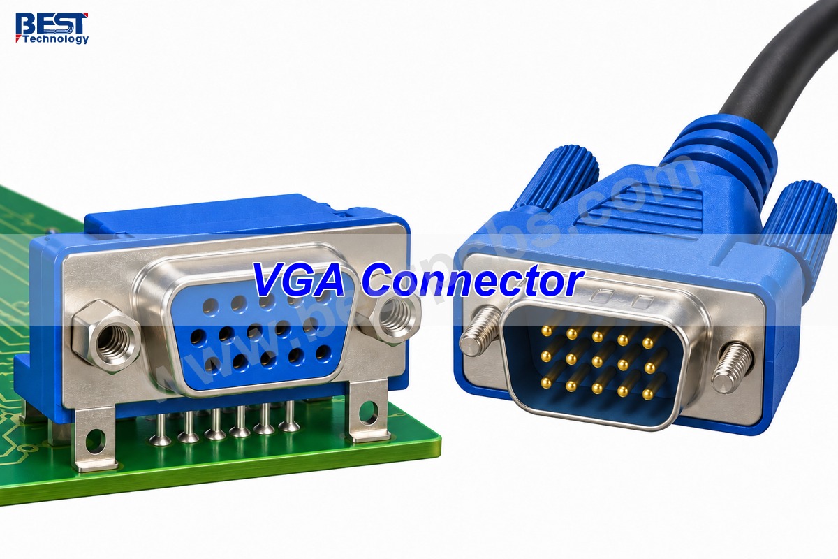
A vga connector is a 15-contact, three-row D-sub interface that carries analog video between equipment and a display. It transmits separate red, green and blue signals, synchronization signals and, on DDC-compatible equipment, display-identification data. It does not carry standard audio. The familiar blue port is usually a female receptacle; a cable plug normally has male pins.
For a replacement or custom PCB, matching the connector’s appearance is only the beginning. Pin numbering, mounting dimensions and signal conversion determine whether the connection works. A VGA plug cannot become an HDMI interface through a simple change of wiring.
Key Takeaways
- Standard VGA uses 15 contacts in three rows, commonly called DE-15, HD-15 or high-density D-sub.
- RGB occupies pins 1–3; horizontal and vertical sync use pins 13 and 14.
- Connector mating-face and solder-side views are mirrored. A footprint must follow the selected part’s drawing.
- VGA carries analog video, while HDMI carries digital video and audio. Conversion requires active electronics.
- RGB routing, connector anchoring and shell grounding need separate design checks.
- Continuity testing cannot verify image quality; a functional display test is also needed.
What Does a VGA Connector Look Like?
A VGA connector has a D-shaped metal shell surrounding three rows of five contacts, with screw fasteners on either side.
The D shape helps prevent reversed insertion, while the screws keep a cable seated. Blue insulation is common but not mandatory. Count the contacts rather than identifying a port by color: a two-row, nine-contact D-sub connector is not the standard 15-contact VGA interface.
At EBest Circuit, we support the PCB and assembly around display interfaces. Our PCB assembly service can combine component sourcing, board assembly and the agreed inspection or functional test. For a VGA design, the exact connector part number connects the mechanical drawing, footprint and assembly plan.
VGA Connector Types
VGA connector types differ by contact gender, mounting direction and termination method, while retaining the familiar 15-contact mating interface.
| Type | Physical arrangement | Typical use |
|---|---|---|
| Male cable plug | 15 projecting pins | Connecting a cable to an equipment port |
| Female PCB receptacle | 15 socket contacts with board tails | Computer, controller or display interface board |
| Right-angle PCB connector | Mating axis parallel to the PCB | Rear-panel or enclosure-edge port |
| Vertical PCB connector | Mating axis perpendicular to the PCB | Top-entry connections |
| Solder-cup connector | Wire-termination cups at the rear | Custom cable and panel assemblies |
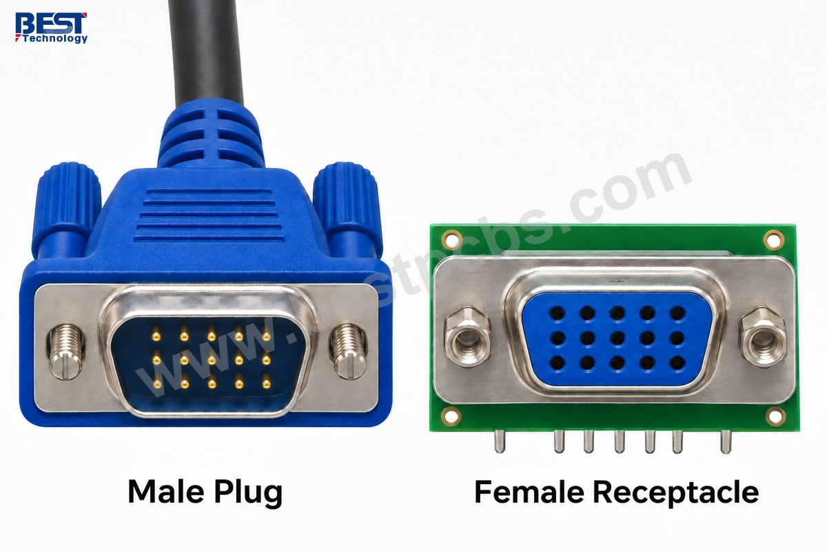
Gender does not establish video direction: a port’s circuit determines whether it is an input or output. Similarly, two right-angle receptacles can share the same mating face but have different board-hole positions, shell supports or connector heights. Do not substitute one footprint for another without checking the drawing.
VGA Connector Pinout
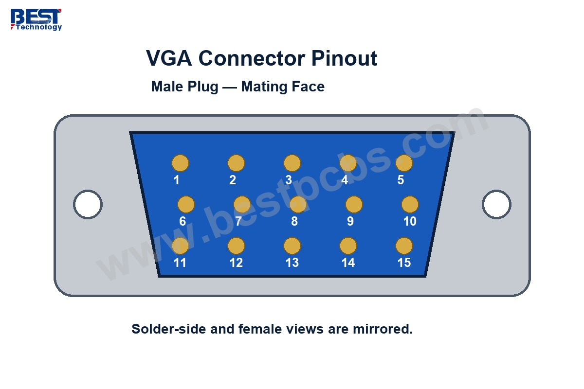
The VGA connector pinout assigns pins 1–3 to analog RGB, pins 6–8 to their returns, and pins 13–14 to horizontal and vertical synchronization.
| Pin | Common signal assignment |
|---|---|
| 1 | Red video |
| 2 | Green video |
| 3 | Blue video |
| 4 | Legacy ID / reserved; equipment-specific |
| 5 | Ground / equipment-specific detection |
| 6 | Red return |
| 7 | Green return |
| 8 | Blue return |
| 9 | DDC supply on supported implementations; check equipment specification |
| 10 | Sync ground |
| 11 | Legacy ID / reserved / ground; equipment-specific |
| 12 | DDC data, SDA |
| 13 | Horizontal sync |
| 14 | Vertical sync |
| 15 | DDC clock, SCL |
DDC means Display Data Channel. It allows the source to read the display’s identification and supported timing information. Older VGA implementations used some auxiliary contacts differently, so the table is not a substitute for the equipment schematic.
The drawing above shows the male plug’s mating face, not its solder side. A female mating-face view is mirrored. Identify pin 1 from the connector drawing before wiring a cable or releasing a PCB footprint.
What Is a VGA Connector Used For?
VGA connects an analog video source to a compatible monitor or projector, especially in existing computers, industrial equipment and installed display systems.
Keeping VGA can make sense when a product must work with an established display. It avoids replacing a functioning monitor solely because a new controller has been introduced. For a new digital-only system, however, adding VGA also means providing analog-video circuitry or a suitable converter.
VGA is not restricted to the original 640 × 480 graphics mode. Higher resolutions are possible, but the connector itself does not guarantee a maximum resolution or refresh rate. The source, monitor, cable quality and analog bandwidth must support the selected timing.
How Does a VGA Connector Compare with HDMI?
VGA sends analog video without standard audio; HDMI sends digital video and can also carry audio.
| Feature | VGA | HDMI |
|---|---|---|
| Video signaling | Analog RGB with synchronization | Digital |
| Audio in the interface | No | Supported |
| Common full-size connector | 15-contact D-sub | 19-contact Type A |
| Conversion between formats | Active conversion required | |
| Typical reason to use it | Compatibility with an existing analog display | Digital display connection |
On an LCD monitor, a digital connection avoids converting a digital source into analog video and then sampling it back into digital form. With VGA, poor cable performance or sampling adjustment can soften text or produce ghosting. HDMI is usually the more straightforward choice when both devices support it natively.
Can You Connect VGA to HDMI with a Passive Adapter?
No. VGA-to-HDMI requires an active converter because analog RGB must be sampled and encoded as digital video.
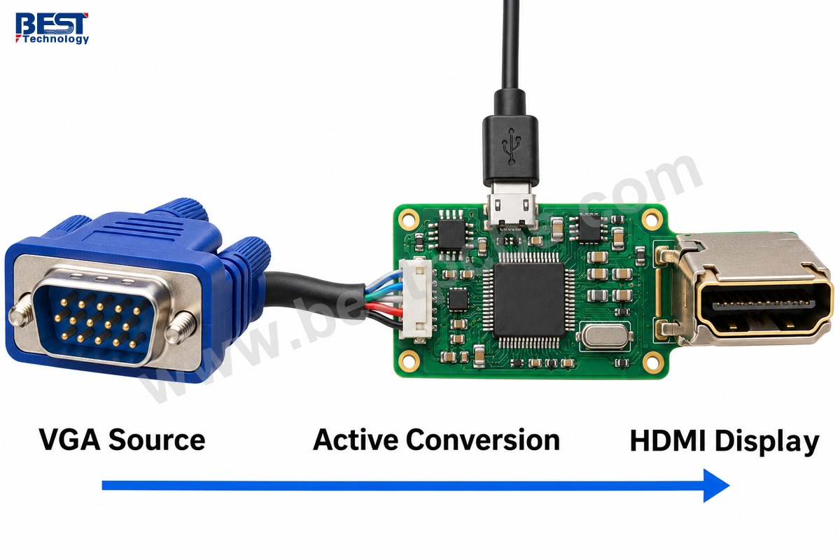
For the reverse direction, an HDMI to VGA connector adapter needs digital-to-analog conversion. An adapter can look like a short cable yet contain active electronics inside its housing. Direction matters: a converter intended for an HDMI source and VGA monitor is not automatically reversible.
- Match the converter’s input to the source and its output to the display.
- Check its supported resolution and refresh rate.
- Provide external power when the converter requires it.
- Use a separate audio input if a VGA-to-HDMI converter must add audio.
DVI-I is a different case: a source that actually provides analog video through its DVI-I port can use a passive VGA adapter. A digital-only DVI-D source cannot supply that analog signal through passive rewiring.
What Matters When Routing VGA Signals on a PCB?
VGA PCB routing needs controlled RGB paths, continuous return references and a connector footprint matched to the selected component.
As a concrete example, NXP’s PTN3355 layout guideline routes the RGB traces to the VGA connector at 75 Ω. That is a design-specific reference, not a reason to assign 75 Ω to every contact. The sync and DDC circuits follow their own driver, receiver and protection requirements.
- RGB routing: follow the video device’s impedance and termination network; avoid unnecessary stubs and reference-plane interruptions.
- Protection: place suitable low-capacitance protection near the exposed connector, following its datasheet layout.
- DDC: check voltage compatibility, pull-ups and the intended supply arrangement rather than treating SDA and SCL as video traces.
- Mechanical fit: confirm the mating axis, panel opening, mounting hardware and board-edge position.
Our PCB design support can help connect the stackup and footprint review with fabrication requirements. Trace width alone does not establish impedance: dielectric thickness, copper geometry and the reference structure also affect it.
VGA Connector Soldering
VGA connector soldering must produce reliable electrical joints while its mounting features absorb cable insertion and screw-loading forces.
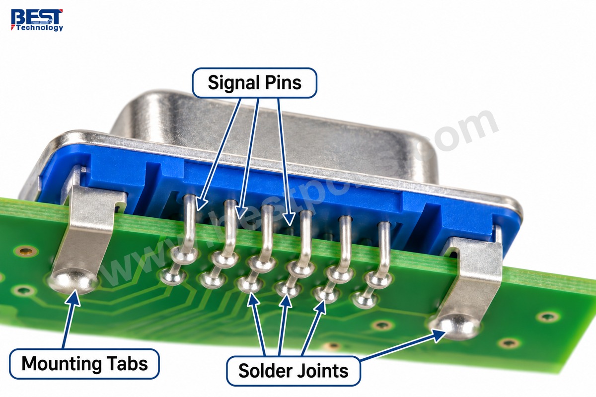
Many board-mounted parts use through-hole tails, although other termination styles exist. The soldering method depends on the connector’s process rating and the assembly design. A plastic housing rated for one process must not be assumed suitable for another.
- Inspect signal pins for bridges, incomplete wetting and damaged pads.
- Check that mounting tabs and jack hardware are fitted as specified.
- Verify connector seating and alignment with the enclosure.
- Inspect shell-to-ground connections against the approved EMC design.
At EBest Circuit, we include the connector drawing and agreed inspection criteria in the assembly review. Signal-pin solder joints should not be the only support for a cable that receives repeated handling.
How Do You Troubleshoot a VGA Connection?
Start with the display’s selected input, cable seating and supported video timing before assuming the PCB has failed.
- Confirm the signal path. Verify source output, monitor input and any converter’s direction and power.
- Substitute a known-good cable. Inspect for bent or recessed contacts with the equipment powered down.
- Choose a supported timing. Use the monitor and converter specifications, not a connector label.
- Separate the symptom. A missing color suggests an RGB path fault; unstable synchronization and failed display detection involve different circuits.
- Test the assembly. After connectivity checks, verify color channels, synchronization and display detection with the intended display.
Continuity checks must be performed on disconnected, unpowered hardware. A continuity result does not prove analog bandwidth or picture quality. For a production test, define the display timing and visible pass/fail pattern instead of accepting any image as sufficient.
FAQs About VGA Connectors
Is DE-15 the same as DB-15?
The familiar three-row VGA connector is properly described as DE-15 or HD-15. It is often sold as DB-15, but that name can also cause confusion with a different two-row D-sub. Confirm the contact layout.
Can a USB-C port drive a VGA monitor?
Yes, with a compatible active adapter and a USB-C source that supports the adapter’s required display mode. A USB-C connector alone does not guarantee video output. USB graphics adapters are a separate product category with their own requirements.
Does a VGA cable carry sound?
No. Standard VGA carries video and associated control signals. Some cable assemblies add a separate audio lead, but that sound does not travel through the standard VGA contacts.
Is there one maximum VGA cable length?
No single length guarantees a usable picture at every timing. Cable construction, shielding, analog bandwidth and equipment performance affect the result. Validate the intended cable length at the actual operating resolution.
Will a passive VGA splitter create two independent desktops?
No. It cannot create an additional graphics output or independent image. A suitable distribution amplifier can send the same video to multiple displays; separate desktops require a source architecture that supports multiple outputs.
Need a PCB Assembly with a VGA Interface?
A dependable VGA interface combines the correct pinout, a mechanically sound connector and a verified analog-video path. These checks belong in the design and assembly plan, not only in final troubleshooting.
For a custom controller or display-interface board, send the connector part number and project requirements to sales@bestpcbs.com. We can review PCB fabrication, assembly and the functional checks needed for your build.