Single-phase power is usually the practical choice for lighter, distributed loads, while three-phase power is better suited to high and relatively continuous loads. The correct choice depends on available utility service, equipment nameplates, peak demand, motor starting behavior, installation cost, power quality, and local electrical rules. Voltage alone does not identify the phase system.
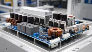
Inside modern equipment, the choice of supply changes the hardware. An inverter, variable-frequency drive, charger, compressor controller, or motor-control PCB must match its input. Phase configuration affects the rectifier, DC-link ripple, current paths, protection devices, thermal design, insulation review, and validation plan. Check both the facility service and the PCB input specification before selecting equipment.
What Is the Main Difference Between Single Phase and 3 Phase Power?
The main difference is the number and timing of AC voltage waveforms. A single-phase source provides one alternating waveform. A three-phase source provides three waveforms separated by 120 electrical degrees. That spacing allows the combined three-phase power delivered to a balanced load to remain much steadier through each cycle.
The difference between single phase and three phase power is not simply “two wires versus three wires.” A single-phase circuit may be line-to-neutral or line-to-line, depending on the supply system. A three-phase service may be three-wire delta or three/four-wire wye. Protective earth is separate from the normal current-carrying conductors and must never be counted as a phase conductor.
| Comparison | Single Phase | Three Phase | Decision Impact |
| AC waveforms | One | Three, 120° apart | Three-phase delivery is smoother for balanced loads |
| Typical load scale | Light to moderate | Moderate to high | Match service capacity to measured demand |
| Motor behavior | Often needs an auxiliary starting method | Naturally produces a rotating field | Three-phase power suits many industrial motors |
| Distribution | Simple for small branch loads | Efficient for larger balanced loads | Facility scale affects conductor and panel choices |
| Common setting | Homes, offices, light equipment | Factories, large HVAC, pumps, drives | Actual service varies by country and utility |
How Do Single-Phase and Three-Phase Power Systems Work?
Both systems use alternating voltage, but they distribute the cycle differently. In a single-phase circuit, voltage rises, crosses zero, reverses polarity, and repeats at the system frequency. Energy delivery to a resistive load varies during that cycle, although heaters, lights, electronic power supplies, and small appliances can operate normally with suitable design.
A three-phase generator or transformer provides three sinusoidal voltages with the same frequency and nominal magnitude. Their 120-degree displacement means one phase approaches a peak while another moves away from it. Under ideal balanced sinusoidal conditions, the combined instantaneous power is constant.
Three-phase systems commonly use wye or delta connections. Wye can provide both line-to-line and line-to-neutral voltages when a neutral is available. Delta normally provides line-to-line connections and may have no neutral. The service configuration must be confirmed before specifying equipment because it affects insulation, switching, protective devices, load balancing, and available utilization voltages.
How Do Voltage, Current, Wiring, Power Factor, and Load Capacity Compare?
At the same real power and comparable voltage, a balanced three-phase load generally needs less line current than a single-phase load. However, voltage standards, conductor arrangements, earthing methods, harmonics, power factor, and permitted loading differ by region. Nameplate and local design data are more reliable than a generic voltage chart.
| Dimension | Single Phase | Three Phase | Engineering Check | Common Error |
| Voltage | Line-to-neutral or line-to-line | Line-to-line and sometimes line-to-neutral | Read service and equipment nameplates | Assuming voltage proves phase count |
| Current | Entire load uses one phase path | Balanced load is shared across three phases | Calculate with measured PF and efficiency | Comparing amperes at different voltages |
| Wiring | Usually line and neutral, or two lines | Three lines, with optional neutral | Confirm wye/delta and earthing system | Counting protective earth as neutral |
| Power factor | Depends on load and input circuit | Depends on load, balance, and drive | Use analyzer or rated data | Assuming phase count guarantees high PF |
| Load capacity | Practical for smaller services | Scales efficiently for larger loads | Check demand, protection, and utility capacity | Selecting by connected load alone |
Power factor is real power divided by apparent power. Motors, transformers, rectifiers, and switch-mode power supplies can draw current that is displaced or distorted relative to voltage. A low power factor increases RMS current for the same useful power, which can increase conductor losses, voltage drop, protective-device loading, and utility demand charges.
How Does Single Phase vs 3 Phase Power Calculation Work?
Single-phase real power uses voltage, current, and power factor; balanced three-phase real power adds the square root of three. Use RMS values and make sure the voltage in the formula matches the system definition. These calculations estimate steady operating conditions and do not replace conductor, breaker, fault-current, or thermal design.
- Define the system. Record phase count, frequency, line-to-line voltage, line-to-neutral voltage if applicable, wye or delta configuration, and whether the load is balanced.
- Collect load data. Use real power, line current, power factor, efficiency, duty cycle, starting current, harmonic content, and manufacturer limits when available.
- Calculate single-phase real power. Use P = V × I × PF. Rearranged for current, I = P ÷ (V × PF).
- Calculate balanced three-phase real power. Using line-to-line voltage and line current, use P = √3 × VLL × IL × PF. Rearranged, IL = P ÷ (√3 × VLL × PF).
- Include efficiency where input power is required. For a motor with mechanical output power Pout, estimate electrical input as Pin = Pout ÷ η, then use input power in the current equation.
- Validate against measured demand. Confirm phase currents, voltage balance, power factor, harmonics, starting behavior, and temperature under representative operating conditions.
For example, a balanced 15 kW load at 400 V line-to-line and 0.90 power factor draws approximately 24.1 A: 15,000 ÷ (1.732 × 400 × 0.90). A 15 kW single-phase load at 230 V and the same power factor draws approximately 72.5 A. These examples compare formula behavior only; they do not specify a safe circuit or prove that either supply is available.
Nonlinear electronic loads require extra care. A basic power-factor value may not describe crest factor, harmonics, neutral current, capacitor ripple, or repetitive peak current. Use a suitable power analyzer and the equipment manufacturer’s data when sizing real systems. For worked DC, single-phase, and three-phase conversions, see the watts-to-amps formulas and examples.
Which Single Phase vs 3 Phase Power Pros, Cons, and Applications Matter Most?
Single phase is usually preferable for smaller intermittent loads, while three phase is usually preferable for high continuous power and industrial motors. The deciding factors are available service, peak current, voltage drop, starting torque, duty cycle, conversion equipment, and installation cost. Neither option is universally superior.
Single-phase advantages and applications include:
- Simpler service for homes, small offices, lighting, receptacles, heaters, and many low-power electronic loads.
- Wide compatibility with household appliances, benchtop instruments, small chargers, and portable equipment.
- Lower initial complexity where demand is modest and the existing service already has adequate capacity.
- Practical operation for intermittent loads that do not require high motor starting torque.
Single-phase limitations include higher current as power rises, pulsating motor torque, auxiliary starting components, and less convenient scaling for large loads.
Three-phase advantages and applications include:
- Efficient distribution to large motors, pumps, compressors, HVAC equipment, machine tools, ovens, and production lines.
- Lower line current for a given balanced power level under comparable voltage and power-factor conditions.
- Smoother motor torque and natural starting field for common three-phase induction motors.
- Flexible facility distribution because a suitable wye service can support both three-phase loads and balanced single-phase branches.
Three-phase limitations include greater protection complexity, phase-sequence requirements, voltage-unbalance risk, and possible utility upgrade charges. It is unnecessary for many light loads.
How Do Motor Starting Torque, Efficiency, and Electricity Costs Compare?
Three-phase motors generally offer smoother torque and simpler self-starting behavior, while total electricity cost depends on the complete motor-driven system. A phase comparison alone cannot predict the bill. Motor efficiency, loading, controls, run hours, power factor, demand charges, maintenance, and mechanical losses often matter more.
| Motor Factor | Single-Phase Motor | Three-Phase Motor | Cost Effect |
| Starting | Often uses capacitor or auxiliary winding | Naturally rotating magnetic field | Starting method affects components and service |
| Torque | More pulsation is common | Smoother torque is common | Load stability affects wear and output quality |
| Efficiency | Suitable for many smaller ratings | Strong options across industrial ratings | Compare rated efficiency at the actual load |
| Controls | Motor type limits control choices | Well suited to VFD control | Speed control may save energy on variable loads |
| Service | Simple where single phase exists | Requires three-phase source or suitable drive | Conversion and upgrades affect ownership cost |
When comparing 3 phase vs single phase electricity cost, separate four categories. Utility and installation costs include the service upgrade, transformer, panel, protection, wiring, and permits. Equipment costs cover the motor, starter, VFD, filters, and spares. Operating and lifecycle costs include measured kWh, demand, power-factor penalties, downtime, maintenance, replacement, and process losses.
Compare motors at the same required shaft output, speed range, duty, enclosure, efficiency class, and load profile. A high-efficiency motor running far below its intended load may not provide the expected system savings. Adjustable-speed control can reduce energy use when a pump or fan process genuinely allows reduced speed. Calculate the savings from the load profile rather than from phase count.
How Does Single Phase vs 3 Phase Power Affect Inverter and Motor Control PCB Design?
The supply phase changes the input rectifier, DC-link behavior, current spectrum, protection architecture, and validation conditions of an inverter or motor-control PCB. The inverter output can still provide three controlled phases to the motor, but the front end must first convert the available AC input into a stable DC bus.
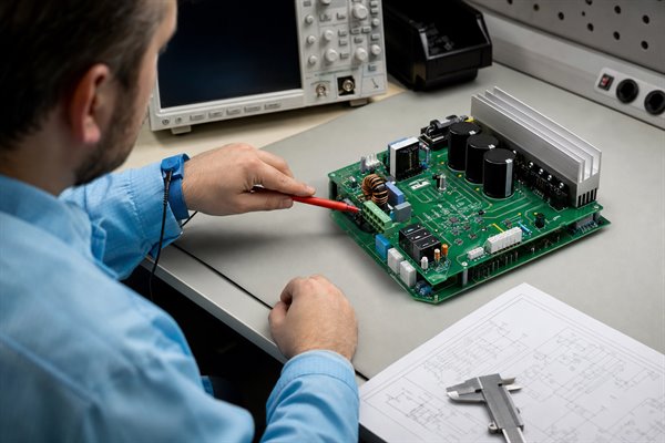
- Define the input envelope. Specify nominal voltage, tolerance, frequency, transient environment, phase configuration, earthing system, expected source impedance, and allowable imbalance.
- Select the rectifier topology. A single-phase bridge typically uses four diodes or controlled devices. A three-phase six-pulse bridge uses six and produces a different ripple pattern and input-current spectrum.
- Size the DC link. Single-phase rectification commonly creates stronger twice-line-frequency energy pulsation. Three-phase rectification produces higher-frequency ripple with lower energy variation for comparable power, but device commutation and harmonics still require analysis.
- Control inrush and surges. Pre-charge paths, relays, NTC devices, fuses, surge protection, discharge circuits, and contact ratings must match capacitor energy and fault conditions.
- Design the current paths. Rectifier, capacitor, shunt, bus, power-module, connector, and return paths need low inductance and adequate copper cross-section. Parallel paths must share current predictably.
- Control EMI. Place filters, common-mode chokes, capacitors, shields, switching loops, chassis connections, and isolation boundaries according to measured emission paths and product compliance requirements.
- Validate abnormal conditions. Test loss of phase where applicable, voltage imbalance, brownout, overvoltage, regeneration, blocked motor, rapid restart, cooling failure, and protective shutdown without assuming that firmware alone provides safety.
Which PCB Design Parameters Change Between Single-Phase and Three-Phase Inputs?
The parameters that change most are input current, rectifier stress, DC-link ripple, conductor geometry, protection ratings, thermal paths, and isolation requirements. Phase count alone is not enough. Working voltage, pollution degree, material group, altitude, coating, enclosure, transient category, cooling, and the applicable product standard determine the final board rules.
| PCB Parameter | Single-Phase Influence | Three-Phase Influence | Required Evidence |
| Rectifier devices | Single bridge and concentrated input pulses | Six-pulse bridge and phase commutation | Voltage, surge, current, loss, and thermal calculations |
| DC-link capacitor | Higher low-frequency energy ripple is common | Shorter ripple intervals and less low-frequency energy swing are common | Ripple current, temperature, lifetime, and hold-up analysis |
| Copper paths | Higher current at comparable power may be required | Current is distributed among input phases | IPC-2152-based analysis plus prototype temperature test |
| Clearance and creepage | Based on actual working and transient voltages | Line-line voltage may govern some barriers | Product safety standard and insulation coordination review |
| EMI filter | Single-phase common and differential paths | Three-line common-mode and phase interactions | Pre-compliance conducted-emission measurements |
| Input protection | Line configuration and prospective fault current | All phases, phase loss, sequence, and imbalance | Fault analysis and coordinated protective-device data |
PCB copper should not be selected from a single universal “amps per millimeter” rule. External and internal layers dissipate heat differently, and nearby copper, vias, solder, airflow, board thickness, ambient temperature, and allowable rise all affect capacity. Use an accepted current-carrying method, then validate the assembled board at worst-case RMS current and cooling conditions. This PCB trace design and current-capacity reference provides a practical sizing sequence.
Likewise, creepage and clearance cannot be copied from a generic internet table. The design team must identify the relevant safety standard, insulation function, voltage waveform, overvoltage category, pollution degree, material comparative tracking index, altitude, coating qualification, and manufacturing tolerances. Slots and barriers can help only when their geometry and production controls satisfy the applicable rules.
Which IEC and IPC Requirements Should a Power Electronics PCB Design Review Verify?
IEC requirements define the installation, motor, drive, EMC, and safety context; IPC requirements define the printed board and assembly controls. No single IEC or IPC document certifies the entire product. The applicable product standard, destination market, voltage class, environment, and end use determine the final compliance set.
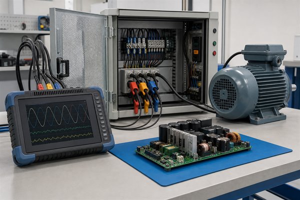
- Confirm the installation basis. IEC 60364-1:2025 states the fundamental principles for low-voltage installations. Use it with the applicable IEC 60364 parts or locally adopted code for electric-shock protection, overcurrent protection, isolation, earthing, verification, and environmental conditions.
- Confirm motor and drive requirements. Use the applicable IEC 60034 documents and the IEC 61800 family for adjustable-speed drives. IEC 60034-26:2026 addresses voltage unbalance in three-phase cage motors, while IEC 60034-30-1:2025 defines motor efficiency classes. Include insulation stress, EMC, and safety requirements where relevant.
- Define generic PCB design rules. Apply IPC-2221C, published in 2023, with the appropriate sectional standard, such as IPC-2222 for rigid organic boards. Verify the revision required by the customer and product contract.
- Review current-carrying conductors. Where the contract accepts IPC-2152, use its methods as an engineering basis for conductor temperature behavior. Because IPC lists the document as no longer maintained, also confirm current customer, product-standard, and manufacturer requirements. Validate the real stackup, copper distribution, assembly, airflow, ambient, and prototype temperature.
- Specify board performance. For rigid boards, IPC-6012F is the current 2024 qualification and performance specification at the time of this review. Apply the agreed performance class, product-specific addendum, and contract revision.
- Specify assembly acceptance. J-STD-001J defines soldered assembly requirements, while IPC-A-610J provides acceptance criteria. Both were released in 2024. Define class, special processes, cleanliness, coating, and inspection evidence rather than citing a standard name alone.
- Close the validation loop. Record schematic review, insulation analysis, DFM findings, thermal test conditions, power-quality limits, dielectric or safety tests, functional protection tests, and deviations approved by responsible engineers.
Cite each standard by revision and contractual applicability. A PCB can meet fabrication acceptance criteria yet remain unsafe if product-level insulation, enclosure, wiring, cooling, or protection is inadequate.
Qualified personnel must perform energized measurements with suitable instruments, protection, procedures, and local code requirements. Conductor color or one voltage reading cannot establish a safe connection.
FAQs About Single Phase vs 3 Phase Power
Q1: Is 240 V always single phase?
A1: No. Voltage does not uniquely identify phase count. Depending on the service, approximately 230–240 V may be line-to-neutral on three-phase wye or line-to-line on a single-phase system. Check utility documents, the panel schedule, meter, conductors, protective devices, and equipment nameplate. Qualified testing is required when records are incomplete.
Q2: How can I tell whether a building has single-phase or three-phase power?
A2: Check verified service records before inspecting live equipment. Review the utility bill or service agreement, main-panel label, meter documentation, incoming line conductors, and breaker arrangement. Equipment nameplates show individual load requirements, not every service available in the building. Never remove covers or probe live conductors without suitable qualifications and equipment. Ask the utility or a licensed professional when records are unclear.
Q3: Why do homes usually use single phase while factories use three phase?
A3: Homes usually suit smaller single-phase loads, while factories often need three-phase distribution for large continuous loads. Factories may run large motors, compressors, ovens, HVAC systems, and drives simultaneously. Three-phase distribution supports higher balanced power with lower line current under comparable conditions and smoother motor torque. Exceptions exist, so utility infrastructure and measured demand remain decisive.
Q4: Can a three-phase motor run from a single-phase supply?
A4: A standard three-phase motor cannot run from single phase by direct connection. A suitable VFD or phase converter may create a three-phase output. However, verify its input current, voltage, power, torque, speed range, cooling, harmonics, protection, motor compatibility, and manufacturer ratings. Some drives require derating on single-phase input, and some three-phase-input drives do not permit it at all.
Q5: Does three-phase power always reduce the electricity bill?
A5: No. Three-phase power does not automatically reduce the electricity bill. Billing depends on kWh, peak demand, tariffs, power factor, operating schedule, and utility rules. Three-phase distribution can reduce current and conductor losses for large balanced loads. However, service upgrades, transformers, switchgear, VFDs, or converters add cost. Compare measured load profiles and lifecycle cost instead of assuming phase count lowers the bill.
Q6: Is three-phase power safer than single-phase power?
A6: Neither system is inherently safe. Three-phase equipment may involve higher line-to-line voltage, phase-sequence hazards, and greater available fault energy. Single-phase circuits can also cause fatal shock, burns, fire, and arc hazards. Safety depends on proper insulation, earthing, overcurrent protection, isolation, enclosure integrity, verification, and qualified personnel following applicable rules.
Q7: What happens when a three-phase load becomes unbalanced?
A7: Phase unbalance raises electrical and mechanical stress. Current and voltage become unequal among phases, which can increase losses, heating, vibration, torque ripple, neutral current, and protective-device stress. Motors are particularly sensitive to voltage unbalance because current unbalance can be much larger than the voltage difference suggests. Measure all phase-to-phase voltages and line currents under representative load, investigate the source, and follow the equipment limits instead of relying on a single average value.
Q8: What is the difference between kW and kVA in this comparison?
A8: kW is real power; kVA is apparent power. Kilowatts represent power converted into work and losses, while kilovolt-amperes come from RMS voltage and current. Power factor equals kW divided by kVA. Cables, transformers, generators, rectifiers, and protective devices must handle the resulting current, while energy charges commonly emphasize real energy. Both values support reliable sizing.
Q9: Does a three-phase PCB require three separate circuit boards?
A9: No. A three-phase design does not require three separate PCBs. One PCB can accept and control all three input phases. A typical design may include a three-phase rectifier, protection and sensing for each line, a shared DC link, gate drivers, an inverter bridge, current measurement, isolation, and digital control. The choice between one board and several depends on voltage, power, cooling, enclosure, serviceability, safety separation, manufacturing constraints, and product architecture.
Q10: What information should be sent for a power electronics PCB quotation?
A10: Send complete fabrication, assembly, electrical, thermal, and compliance requirements. Provide fabrication data, drill files, stackup, copper weights, dimensions, material requirements, surface finish, solder mask, controlled features, acceptance class, quantity, and testing requirements. For assembly, add the BOM, centroid data, assembly drawings, approved substitutions, programming and functional-test requirements. Also identify the input voltage range, phase configuration, maximum RMS and surge currents, insulation requirements, thermal limits, and applicable product standards.
The practical choice between single phase vs 3 phase power comes from the complete load and compliance picture. Review available service, current, motor behavior, energy profile, input electronics, protection, PCB construction, and verification evidence. Use measured data and current local requirements before approving equipment or connecting a power converter.
Are you sourcing an inverter, motor-control, or power electronics PCB for OEM, ODM, prototyping, volume production, or a custom project? Contact the EBest Circuit engineering team at sales@bestpcbs.com for technical review and a quotation.