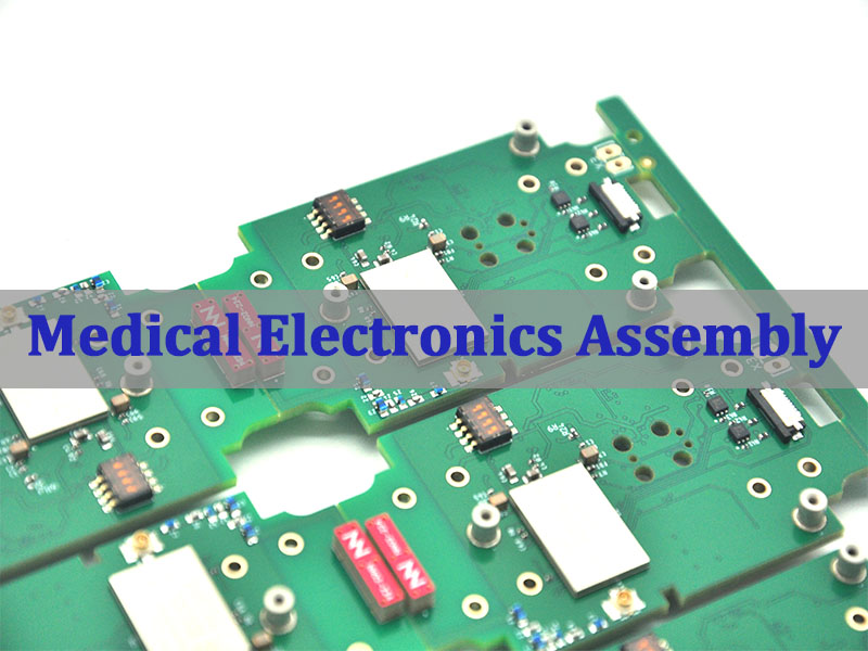
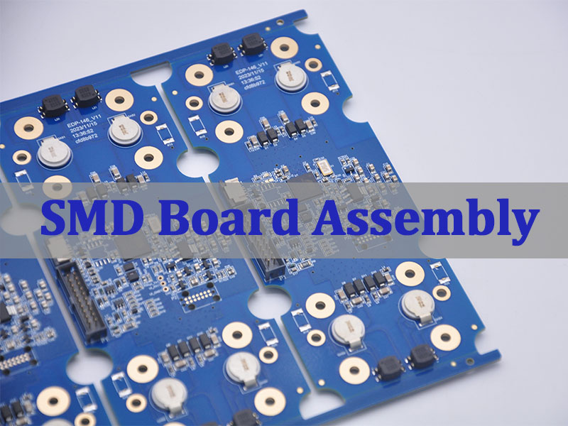
A static transfer switch can move a critical load between two AC power sources fast enough to avoid an unacceptable interruption. For the OEM building that equipment, however, fast transfer depends on more than a switching specification. The sensing, control, gate-driver, power-supply, communication, and protection circuits must also be manufactured from the correct files and components.
If those PCB assemblies are quoted from incomplete information, the project can lose time through material substitutions, high-voltage spacing questions, thermal changes, connector mismatches, or an inspection plan that arrives too late. EBest Circuit (Best Technology) supports released-design PCB manufacturability review, PCB fabrication, BOM sourcing, SMT and through-hole assembly, and agreed testing assistance. Send your fabrication files, BOM, assembly data, and test requirements to sales@bestpcbs.com for a project-specific review.
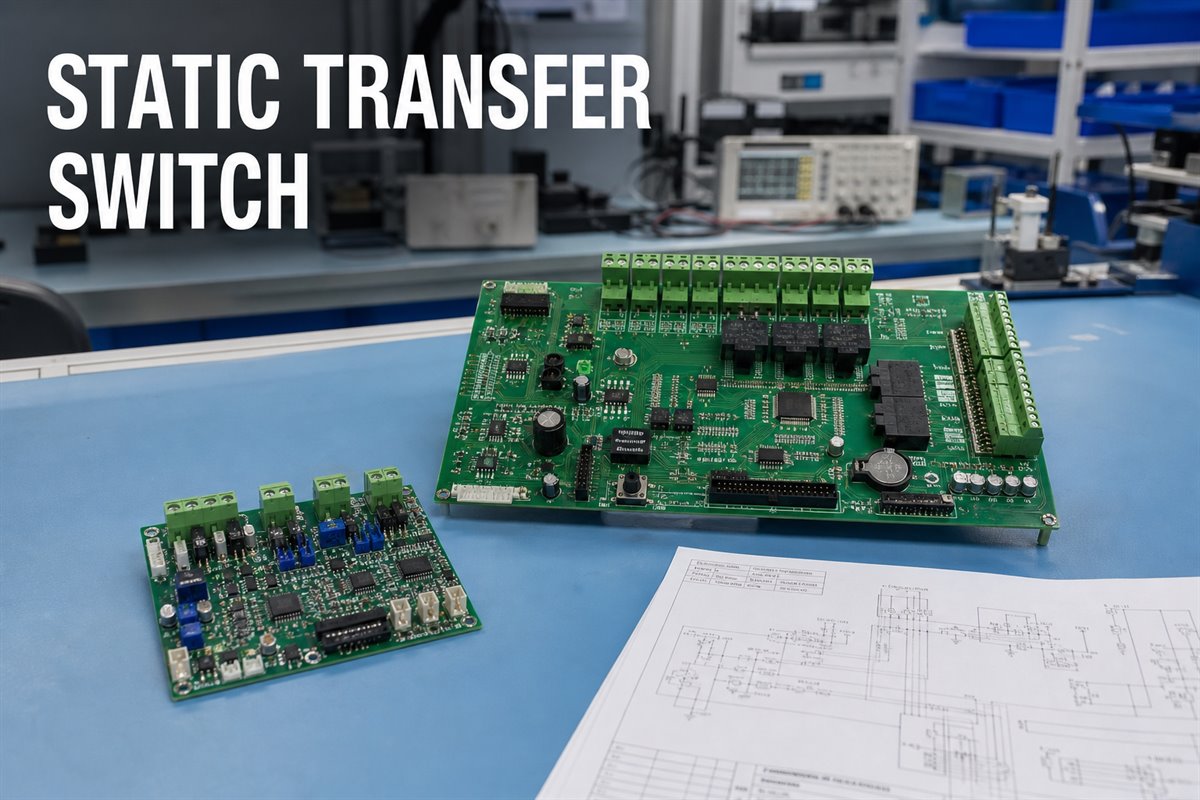
What Does a Static Transfer Switch Do?
A static transfer switch monitors two available AC sources and transfers the connected load when the preferred source no longer meets the system’s defined conditions. Unlike a mechanically operated transfer device, the power path normally uses solid-state switching devices such as SCRs or thyristors. The exact transfer conditions, sequence, and timing depend on the released product design.
For an OEM, the practical benefit is continuity for a sensitive load. The manufacturing implication is that several electronic functions must work together:
- source-voltage and frequency sensing;
- synchronization or phase-related measurement, when required by the design;
- decision and protection logic;
- isolated gate-drive control;
- auxiliary power conversion;
- status indication, alarms, and communications;
- temperature monitoring and cooling control.
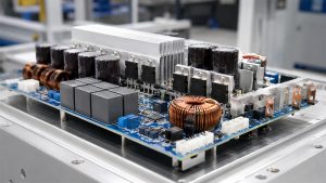
These functions may be divided among several PCBAs or combined differently in each product. A PCB supplier should therefore manufacture the customer’s released architecture, not assume that every static switch uses the same board set.
The customer remains responsible for the STS topology, sensing thresholds, transfer logic, component selection, firmware, safety analysis, and final equipment validation. The PCB/PCBA manufacturer can check whether the released board data is manufacturable and whether the quoted build matches that data.
How Does STS vs ATS Change the Electronics You Need to Build?
The useful question in an STS vs ATS comparison is not simply which device is faster. It is which electronic scope the OEM must release, source, assemble, and test.
An ATS commonly depends on mechanical switching elements, while an STS uses solid-state power devices and electronic sensing and control. This difference can increase the amount of circuitry associated with gate drive, isolation, signal conditioning, auxiliary power, protection, and thermal monitoring. It can also create different PCB spacing, copper, component, and test requirements.
Do not turn the comparison into a universal timing promise. Transfer performance depends on source conditions, load characteristics, control strategy, device ratings, and the completed equipment. Instead, use the comparison to define the manufacturing package:
- Which PCBAs belong to the static transfer switch?
- Which high-voltage and low-voltage domains appear on each board?
- Which components are safety-critical or substitution-controlled?
- Which firmware is needed before functional testing?
- Which tests can be completed at board level, and which require the full system?
This distinction prevents a supplier from treating an STS control board as an ordinary low-voltage controller and quoting only from board dimensions and layer count.
Which PCB Assemblies Matter Most in a Static Transfer Switch?
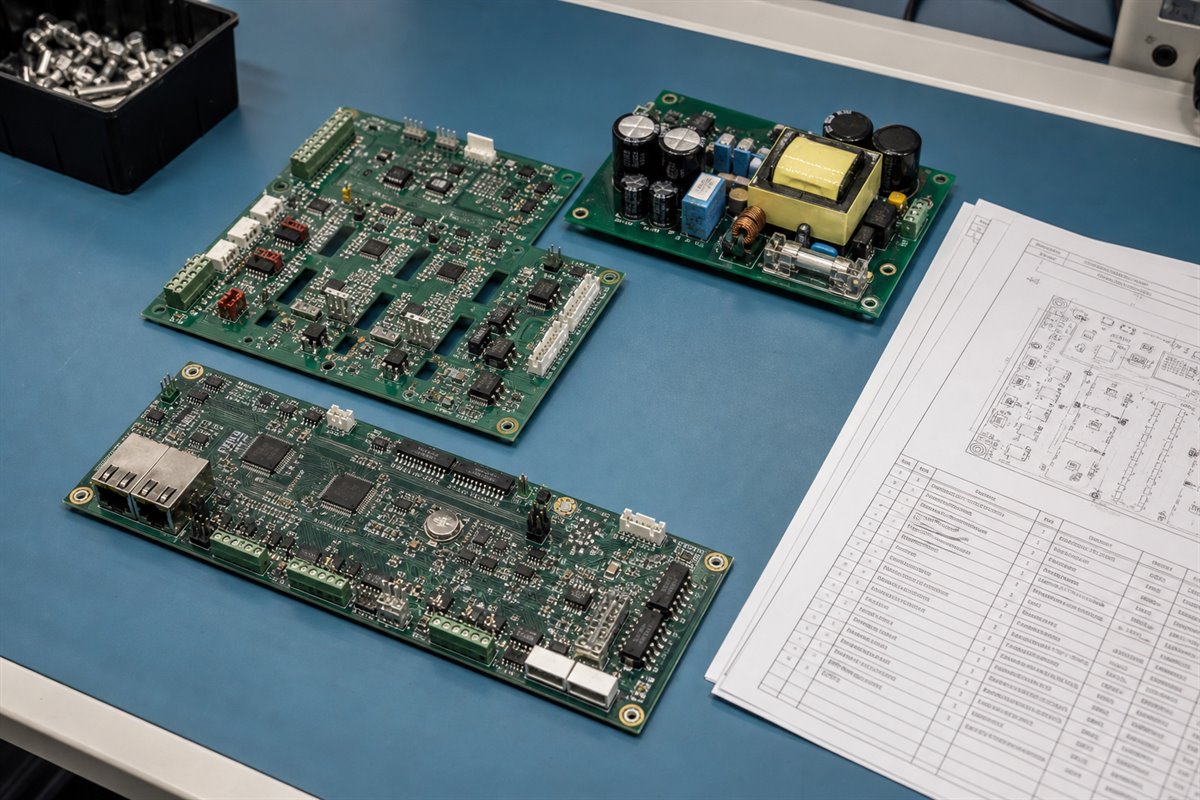
Knowing the board-level scope helps purchasing teams compare equivalent quotations and helps engineers avoid missing interfaces. Depending on the released architecture, a static transfer switch may include:
- Control PCBA. Processes measurements, executes customer-developed logic, manages alarms, and coordinates the commanded transfer.
- Sensing PCBA. Conditions voltage, current, frequency, phase, temperature, or status signals for the controller.
- Gate-driver PCBA. Provides the isolation, pulse control, and interfaces required by the selected power-switching devices.
- Auxiliary power-supply PCBA. Produces the regulated rails needed by the controller, sensors, drivers, relays, displays, and communications.
- Interface or communication PCBA. Supports indicators, controls, network interfaces, or remote monitoring defined by the product.
- Protection or interconnection board. Carries customer-defined protection components, connectors, terminal interfaces, or distribution paths.
Not every design separates these functions. The RFQ should use the actual board part numbers and revisions rather than a generic label such as “STS boards.” That gives the supplier a clear deliverable and prevents one quotation from including three PCBAs while another includes five.
For each PCBA, identify whether the order covers bare PCB fabrication, customer-supplied components, full BOM sourcing, assembly, programming, conformal coating, inspection, or testing assistance. Clear scope produces a quotation that purchasing can use instead of a low initial price followed by additions.
Which Manufacturing Risks Can Delay an STS Build?
Most avoidable delays begin before assembly. The supplier receives enough information to calculate a price, but not enough to confirm that the board can be built and accepted.
Release these risk items before material is purchased:
- Unclear high-voltage boundaries. The fabrication data may not show the voltage domains, required spacing, slotting, barriers, or customer-approved constraints.
- Late stack-up changes. A changed dielectric construction can affect finished thickness, copper geometry, controlled impedance, isolation features, and mechanical fit.
- Heavy-copper or current-path assumptions. Copper weight alone does not define current capacity or thermal performance. The approved layout, copper construction, temperature limits, and system cooling remain essential.
- Mixed component technologies. Large terminals, transformers, relays, heat-sensitive parts, fine-pitch devices, and through-hole power components may require different assembly controls.
- Uncontrolled substitutions. A component that looks electrically similar may differ in package, isolation rating, thermal behavior, qualification status, or firmware compatibility.
- Incomplete test access. Important nodes may be inaccessible after assembly, while the required fixture or firmware has not been released.
- Mechanical interface errors. Connector height, orientation, mounting holes, heat-sink interfaces, and enclosure clearances can stop final integration even when the PCBA passes electrical inspection.
A manufacturability review can identify conflicts between the released files and the intended fabrication or assembly process. It does not replace the customer’s electrical, thermal, mechanical, or safety design decisions.
What Should You Confirm Before Ordering Static Switch PCBAs?
Before ordering static switch PCBAs, make the approved requirement visible in the fabrication drawing, assembly drawing, BOM notes, purchase order, and test specification. A requirement mentioned only in an email is easy to miss during sourcing or production.
Confirm the following before the purchase order:
- current PCB and PCBA part numbers with revision status;
- complete Gerber or ODB++ data, drill files, drawings, and stack-up;
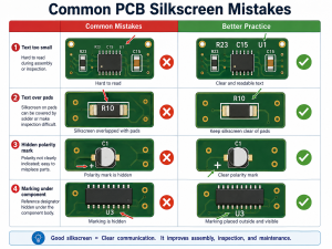
- finished board thickness, copper construction, surface finish, solder mask, and marking requirements;
- voltage domains and customer-specified spacing, slots, barriers, or isolation requirements;
- exact connector, terminal, transformer, optocoupler, driver, controller, and power-device part numbers;
- do-not-substitute items and the approval route for alternatives;
- polarity, orientation, torque, heat-sink, insulation, and mechanical-interface notes;
- programming files, version control, and device-programming instructions;
- inspection standard, acceptance class, sample plan, and required records;
- test procedure, fixture responsibility, limits, and report format.
If any requirement is still pending, identify it as pending. That is safer than allowing each supplier to build a different assumption into the quote.
How Can BOM Sourcing Prevent SCR and Driver-Component Delays?
Critical components can hold up the entire build even when the PCBs are ready. The buyer benefits when availability and substitution rules are checked before the order is released, not after assembly is scheduled.
The BOM should provide the manufacturer part number, description, package, quantity, approved alternatives, and substitution authority for every line. Pay particular attention to:
- SCRs, thyristors, IGBTs, or other customer-selected switching devices;
- isolated gate drivers and optocouplers;
- voltage and current sensing components;
- microcontrollers, DSPs, programmable logic, and memory;
- isolation transformers and auxiliary power modules;
- safety-rated capacitors, resistors, fuses, and protection devices;
- connectors, terminal blocks, relays, and mechanically constrained parts.
For components mounted outside the PCBA, clarify whether they are included in the sourcing scope. A switching module shown on a system drawing may not appear on the assembly BOM, yet purchasing may still expect the PCBA supplier to provide it.
EBest Circuit can source components against a customer-released BOM and raise availability or substitution questions for approval. The customer retains responsibility for selecting the components and approving any alternative that could affect electrical performance, isolation, thermal behavior, compliance, or firmware.
What Inspection and Testing Evidence Should an STS Order Include?
Inspection records help the customer decide whether the delivered PCBAs match the released order. They should be defined before production so that the supplier can price the necessary work and preserve the required evidence.
Match each record to a real acceptance decision:
- material and stack-up confirmation for the bare PCB;
- certificate of conformance when required;
- solder paste inspection and automated optical inspection records where applicable;
- X-ray inspection for hidden joints or selected power and BGA components when specified;
- polarity, orientation, workmanship, and through-hole solder inspection;
- dimensional, connector-position, or mechanical-interface checks;
- programming verification and firmware-version record;
- electrical or functional test results based on customer-provided limits;
- nonconformance, repair, and deviation records;
- serial-number or lot traceability when required.
Board-level testing cannot prove the completed STS will meet its transfer-time, load, fault, thermal, EMC, safety, or reliability requirements. Those are system-level acceptance responsibilities unless a separately defined and authorized test scope says otherwise.
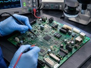
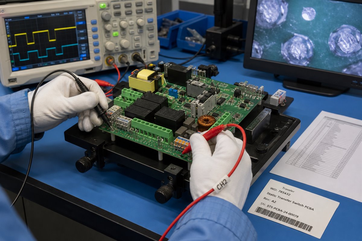
When EBest Circuit assists with functional testing, the RFQ should identify the customer-provided fixture, software, firmware, operating instructions, safe power conditions, expected readings, pass/fail limits, and report format. This turns “function test required” into a test that can actually be quoted and repeated.
Which Files Produce a More Accurate Static Transfer Switch Quote?
An accurate static transfer switch PCBA quote starts with a package that lets the supplier understand what must be delivered. Sending only Gerber files may produce a bare-board price, but it cannot define sourcing, assembly, programming, inspection, or test scope.
Send one controlled RFQ package containing:
- PCB fabrication data and fabrication drawing;
- approved stack-up or construction requirements;
- assembly drawings for top and bottom sides;
- complete BOM with approved manufacturers and substitution rules;
- centroid or pick-and-place data;
- schematic for engineering reference when permitted;
- polarity, orientation, connector, and mechanical-interface notes;
- programming files and instructions;
- workmanship and acceptance requirements;
- inspection and test specifications;
- prototype quantity, expected production quantity, and delivery target;
- required reports, traceability, labeling, and packaging instructions.
Ask the supplier to list assumptions, exclusions, separately priced options, and unresolved engineering questions. This makes quotations easier to compare because each supplier is pricing the same manufacturing outcome.
How Can One PCB and PCBA Supplier Reduce STS Production Handoffs?
Using one supplier for PCB fabrication, BOM sourcing, assembly, and agreed testing assistance can reduce the number of handoffs the OEM must coordinate. The benefit is not simply fewer purchase orders. It is a clearer path from the released PCB construction to the assembled and documented PCBA.
EBest Circuit can support:
- PCB layout manufacturability review against the released requirements;
- prototype and production PCB fabrication;
- BOM sourcing with customer-controlled substitutions;
- SMT and through-hole assembly;
- inspection, programming, and agreed test assistance;
- production records and traceability defined in the order.
This combined scope is useful when a static transfer switch contains several related board assemblies with shared components, connectors, revisions, or inspection requirements. Engineering questions can be raised before fabrication or material purchasing rather than being discovered during final assembly.
The boundary remains important: EBest Circuit does not take ownership of the STS electrical architecture, transfer algorithm, firmware validation, product certification, or final equipment safety unless a separate written scope explicitly defines an authorized activity. We manufacture and assemble to the customer’s released and approved requirements.
FAQs About Static Transfer Switch PCB Manufacturing
Is a static transfer switch the same as an automatic transfer switch?
No. An STS normally uses solid-state switching devices, while an ATS commonly uses mechanical switching elements. The resulting transfer behavior and electronic manufacturing scope can differ. The product designer must determine which architecture suits the application.
Can a PCB supplier select the SCR or thyristor for an STS?
The system designer should select and approve the power-switching device based on the electrical, thermal, fault, control, safety, and qualification requirements. A sourcing supplier can check availability and propose alternatives for customer review, but should not silently replace the approved device.
Does PCBA functional testing prove the complete STS will transfer correctly?
Not by itself. A board-level test can verify specified inputs, outputs, programming, or communication functions. Complete transfer performance depends on the assembled system, sources, load, firmware, switching devices, sensing, cooling, protection, and customer-defined operating conditions.
What should be marked as do not substitute in the BOM?
Mark any component whose replacement could affect electrical performance, isolation, safety, thermal behavior, mechanical fit, programming, qualification, or regulatory evidence. Also state who may approve an alternative and what evidence is required.
Can EBest Circuit manufacture all PCBAs used in a static transfer switch?
EBest Circuit can review and quote released PCB/PCBA packages that fit its manufacturing, sourcing, assembly, and agreed testing capabilities. Feasibility depends on the board construction, components, assembly process, inspection needs, quantities, and test scope. Send the current files to sales@bestpcbs.com for review.
Before releasing your next static transfer switch prototype or production order, confirm the board list, revision, BOM controls, manufacturing requirements, and acceptance evidence. A complete package helps EBest Circuit return a more usable quotation and identify manufacturability or sourcing questions before they become schedule delays.