A silicon controlled rectifier (SCR) is a three-terminal power semiconductor that remains off until its gate receives a suitable trigger. Once the main current reaches the required latching level, the SCR can stay on after the gate signal disappears and normally turns off only when current falls below the holding current.
This switching behavior makes the silicon controlled rectifier useful in controlled rectifiers, motor controls, industrial heating, soft-start circuits, power regulators, and overvoltage protection. Reliable operation also depends on gate drive, load current, firing angle, commutation, voltage transients, surge current, and thermal conditions.
What Is a Silicon Controlled Rectifier (SCR)?
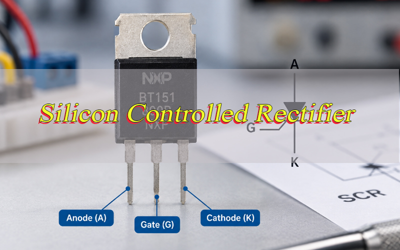
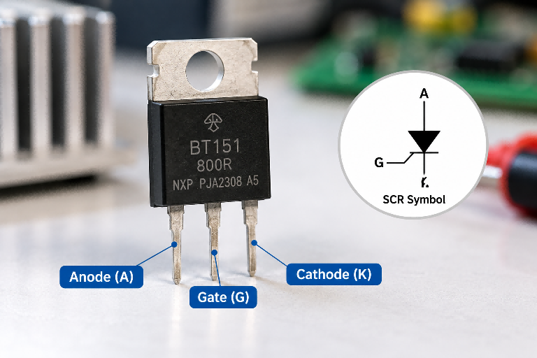
A silicon controlled rectifier is a three-terminal, four-layer PNPN thyristor used for controlled power switching. Its terminals are the anode, cathode, and gate. The anode and cathode form the main current path, while the gate is used to initiate conduction.
Unlike an ordinary rectifier diode, an SCR can remain off while forward biased. The circuit can therefore determine when current begins flowing rather than allowing conduction to start automatically.
Once the device has latched, continuous gate current is normally unnecessary. An SCR is a gate-triggered, current-latched, unidirectional power switch. An SCR is a type of thyristor, but not all thyristors are SCRs.
How Is a Silicon Controlled Rectifier Structured and What Does Its Symbol Show?
A conventional silicon controlled rectifier contains four alternating semiconductor layers arranged P-N-P-N, forming three junctions identified as J1, J2, and J3. The anode connects to the outer P layer, the cathode to the outer N layer, and the gate connects near the cathode-side P region.
The PNPN structure allows the device to remain in a blocking state until a trigger starts the internal regenerative switching process.
The SCR symbol identifies the anode, cathode, and gate and shows a unidirectional main current path from anode to cathode. Its additional gate terminal distinguishes it from a standard rectifier diode.
- Anode: Main-current input during normal forward conduction.
- Cathode: Main-current return.
- Gate: Control terminal used to initiate turn-on.
The gate does not carry the load current. It starts conduction through the main anode-to-cathode path.
How Does a Silicon Controlled Rectifier Work?
A silicon controlled rectifier changes from a forward-blocking state to a conducting state when it is forward biased and receives sufficient gate current.
Before triggering, the anode can already be positive relative to the cathode, but the internal junction arrangement prevents substantial current from flowing. A positive gate signal injects carriers into the PNPN structure and starts regenerative action inside the device.
As this process develops, the effective resistance between the anode and cathode falls rapidly and the main current rises. The SCR then enters its forward-conduction state.
The basic sequence is:
Forward bias → gate trigger → internal regeneration → rising anode current → forward conduction
The gate therefore controls when the transition from blocking to conduction begins. Whether the device remains on afterward depends on the current flowing through the main path.
What Do the Operating States and V-I Characteristics of an SCR Show?
The V-I characteristics of a silicon controlled rectifier show where the device blocks voltage, when turn-on occurs, and how current behaves after the SCR enters conduction.
| State | Condition | SCR Behavior |
|---|---|---|
| Reverse Blocking | Cathode positive to anode | Small reverse leakage |
| Forward Blocking | Anode positive, no effective trigger | SCR remains off |
| Forward Conduction | SCR triggered | High current, low on-state voltage |
In reverse blocking, only a small leakage current normally flows while the reverse voltage remains within the device rating.
In forward blocking, the anode is positive relative to the cathode, but the SCR has not received an effective trigger. This is the operating state that allows controlled switching.
If the forward voltage rises sufficiently, the SCR can reach its forward breakover voltage and enter conduction without an intentional gate signal. In normal circuit operation, gate triggering is usually used before this point is reached.
After triggering, the device enters forward conduction. Current rises sharply while the voltage across the SCR falls to a relatively low on-state value.
The V-I curve therefore shows three useful conditions: blocking, triggering, and conduction.
How Does an SCR Turn On, Latch, and Turn Off?
Turn-on and turn-off in a silicon controlled rectifier are mainly determined by three current values: IGT, IL, and IH.
| Parameter | Function |
|---|---|
| IGT | Gate current required to initiate turn-on |
| IL | Anode current required to establish latching |
| IH | Anode current required to maintain conduction |
When the gate current reaches the required gate trigger current, IGT, the SCR begins turning on. The anode current must then rise above the latching current, IL, before the gate pulse disappears.
If the load current remains below IL, the SCR may turn on briefly and then return to the blocking state.
Once latched, the device no longer depends on continuous gate drive. It remains conductive while the main current stays above the holding current, IH.
The full sequence is:
IGT reached → SCR turns on → current exceeds IL → SCR latches → gate pulse ends → current stays above IH → SCR remains on → current falls below IH → SCR turns off
This explains several common behaviors:
- SCR turns on but will not stay on: The anode current may not reach IL.
- SCR will not turn off: The main current may still be above IH.
- Gate pulse disappears but SCR stays on: This is normal after successful latching.
In an AC circuit, current naturally passes through zero every cycle. When current falls below IH, the SCR can turn off through natural commutation.
In a DC circuit, a natural current zero may not exist. The circuit may therefore require forced commutation or another method of reducing current below IH.
For a conventional SCR, removing the gate pulse alone does not normally turn the device off.
How Does an SCR Control Power in a Rectifier Circuit?
A silicon controlled rectifier controls AC power by changing the point in each cycle at which conduction starts. This trigger position is known as the firing angle, α.
In a simple half-wave controlled rectifier, the SCR becomes forward biased at the beginning of the positive half-cycle but remains off until the gate pulse arrives.
A smaller firing angle turns the SCR on earlier and allows more of the waveform to reach the load. A larger firing angle delays turn-on and reduces the average output.
For an ideal single-phase half-wave controlled rectifier with a resistive load:
Vavg = Vm(1 + cos α) / 2π
The relationship is straightforward:
- Small firing angle: Longer conduction time and higher average output.
- Large firing angle: Shorter conduction time and lower average output.
Load type also affects current behavior.
With a resistive load, current closely follows voltage and normally approaches zero near the end of the half-cycle.
With an inductive load, current lags voltage because energy remains stored in the magnetic field. The SCR can therefore continue conducting after the supply voltage has crossed zero, which affects commutation and transient behavior.
Common SCR power-control circuits include:
- Half-wave controlled rectifiers
- Full-wave controlled rectifiers
- Controlled bridge rectifiers
- Phase-angle controllers
In each case, the firing angle determines how much of the input waveform reaches the load.
Where Are Silicon Controlled Rectifiers Used?
A silicon controlled rectifier is most useful where relatively high voltage or current must be controlled without requiring very high switching frequency.
- Motor control: SCRs can handle substantial current while firing-angle control changes average power delivered to suitable motor circuits. This makes them useful in line-frequency speed control and soft-start systems.
- Industrial heating: Heater loads often operate at mains frequency and do not require high-frequency PWM. SCR phase-angle or burst control can regulate large heater currents without repeated mechanical contact switching.
- Controlled rectifiers: The trigger point can be changed during each AC cycle, allowing the average DC output to be adjusted.
- Battery charging: In suitable charger topologies, SCR triggering can regulate the amount of rectified power delivered to the battery.
- AC voltage control: Delayed turn-on changes the portion of each cycle delivered to the load, allowing line-frequency power regulation.
- Crowbar protection: An SCR can turn on during an overvoltage fault and latch into a low-impedance state. The latching action keeps the fault path active until upstream protection clears the fault.
- Soft-start circuits: Gradually changing the conduction interval reduces the sudden application of full line power.
- Inrush-current control: An SCR can switch or bypass a current-limiting element after startup.
These applications benefit from high blocking voltage, substantial current capability, low gate-drive power, and reliable latching.
How Is an SCR Different From a Diode, TRIAC, MOSFET, and IGBT?
A silicon controlled rectifier differs from other common power devices mainly in its control method, current direction, latching behavior, and useful switching frequency.
| Feature | SCR | Diode | TRIAC | MOSFET | IGBT |
|---|---|---|---|---|---|
| Main Role | Controlled switching | Rectification | AC power control | Fast switching | Power switching |
| Control | Gate turn-on | None | Gate trigger | Gate on/off | Gate on/off |
| Latching | Yes | No | Yes | No | No |
| Direction | Unidirectional | Unidirectional | Bidirectional | Circuit-dependent | Controlled |
| Frequency | Low–moderate | Device-dependent | Low–moderate | High | Moderate–high |
| Common Use | Controlled rectifiers | Rectifiers | AC loads | SMPS/PWM | Drives/inverters |
A diode has no gate and begins conducting automatically when its forward-bias condition is reached. An SCR adds controlled turn-on.
A TRIAC conducts in both directions and is often convenient for single-device AC load control. A conventional SCR is unidirectional.
A MOSFET can normally be turned both on and off through its gate and is well suited to high-frequency PWM and switching power supplies.
An IGBT also supports active turn-on and turn-off and is widely used in motor drives, inverters, and higher-power switching converters.
SCRs are strongest where high-power controlled conduction and latching are useful; MOSFETs and IGBTs are stronger where repeated active switching is required.
Which SCR Datasheet Parameters Matter Most?
When selecting a silicon controlled rectifier, do not rely on voltage and current ratings alone. Blocking voltage, surge capability, gate drive, latching behavior, switching stress, and thermal limits must all match the circuit.
| Parameter | Meaning |
|---|---|
| VDRM | Repetitive forward blocking voltage |
| VRRM | Repetitive reverse voltage |
| IT(AV) | Average on-state current |
| IT(RMS) | RMS on-state current |
| ITSM | Non-repetitive surge current |
| IGT | Gate trigger current |
| VGT | Gate trigger voltage |
| IL | Latching current |
| IH | Holding current |
| VTM | On-state voltage |
| dV/dt | Voltage rise-rate capability |
| dI/dt | Current rise-rate capability |
| Tj | Maximum junction temperature |
| RθJC | Junction-to-case thermal resistance |
VDRM and VRRM should provide margin for actual line variation and switching transients, not only the nominal supply voltage.
IT(AV) and IT(RMS) must be checked against the real current waveform, conduction angle, ambient temperature, and cooling conditions. The headline current rating does not apply equally to every design.
ITSM becomes important during capacitor charging, transformer energization, motor startup, inrush events, and fault current.
IGT and VGT determine whether the gate driver can trigger the SCR reliably across temperature and component variation.
IL and IH should be compared with the real load current, especially in light-load applications.
dV/dt affects susceptibility to false triggering, while dI/dt limits how rapidly current can safely increase during the first part of turn-on.
Finally, VTM, Tj, and RθJC determine whether conduction losses can be removed without exceeding the allowed junction temperature.
Two SCRs with similar voltage and current ratings are not automatically interchangeable.
What Causes False Triggering, Overheating, or SCR Failure?
Common silicon controlled rectifier problems can usually be traced to triggering conditions, current stress, voltage transients, or excessive junction temperature.
- SCR turns on unexpectedly: Excessive dV/dt, gate noise, or switching transients.
- SCR turns on but will not stay on: Anode current does not reach IL.
- SCR will not turn off: Current remains above IH.
- SCR overheats: Conduction losses exceed available cooling.
- SCR fails during startup: Surge current exceeds ITSM.
- SCR fails during turn-on: dI/dt exceeds the safe limit.
- SCR fails with an inductive load: Transient voltage exceeds the blocking margin.
Excessive dV/dt can create displacement current inside the device and contribute to unintended turn-on. Long gate traces, large gate-cathode loops, or routing near fast-switching power nodes can increase sensitivity.
Failure to latch has a different cause. A valid gate pulse may initiate turn-on, but the main current never reaches IL before the pulse disappears.
Overheating is largely a power-loss problem. A useful first estimate is:
Conduction Loss ≈ VTM × Load Current
Actual thermal analysis should also consider RMS current, conduction angle, waveform, duty cycle, ambient temperature, and the manufacturer’s characteristics.
An SCR can therefore operate below its published current rating and still overheat if the thermal path cannot remove the generated heat.
What Protection and PCB Layout Practices Improve SCR Reliability?
Reliable silicon controlled rectifier operation depends on transient control, gate routing, high-current layout, and thermal management.
- Place the RC snubber close to the SCR. Long traces add parasitic inductance and reduce transient-control effectiveness.
- Keep the gate-cathode loop short. A compact loop reduces coupled switching noise.
- Separate gate traces from high-dV/dt nodes. Avoid long parallel routing beside switched power paths.
- Use the correct gate resistor. Gate current should reliably exceed the trigger requirement without exceeding gate ratings.
- Control surge voltage. MOVs, TVS devices, snubbers, or other suppression methods may be required.
- Coordinate overcurrent protection. Fuse behavior should be checked against expected fault current and SCR surge capability.
- Limit excessive dI/dt. Some circuits require added inductance or impedance during turn-on.
- Size the main current path correctly. Trace width, copper weight, via capacity, resistance, and temperature rise all matter.
- Provide a complete thermal path. Heat sinks, thermal interfaces, PCB copper, thermal vias, and airflow can all affect junction temperature.
- Maintain suitable creepage and clearance. Spacing must reflect working voltage, environment, insulation requirements, and applicable safety standards.
For SCR packages with a dedicated auxiliary cathode or gate-reference terminal, use the intended gate return connection where specified rather than sharing a noisy high-current cathode path.
A correct schematic does not guarantee a reliable PCB. A snubber placed too far from the SCR or a gate trace routed beside a high-dV/dt node can still cause false triggering or switching instability.
For high-current designs, the SCR, gate driver, snubber, power loop, and thermal path should be reviewed as one system.
How Can You Test Whether an SCR Is Working Correctly?
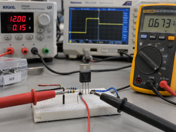
A proper silicon controlled rectifier test should verify blocking, gate triggering, latching, and turn-off. A continuity check can find a shorted device but cannot confirm correct switching behavior.
- Check for an anode-to-cathode short.
With power removed and stored energy discharged, measure between the anode and cathode. A near-short in both directions when the device should be blocking can indicate damage. - Check the gate-to-cathode junction.
Use diode or resistance mode to confirm semiconductor-junction behavior rather than a direct short or permanent open circuit. Exact readings vary by device. - Apply a controlled gate trigger.
Forward bias the SCR through a current-limited load and apply sufficient gate current. The device should enter conduction when the gate drive reaches the required IGT. - Verify latching.
Allow the anode current to rise above IL, then remove the gate pulse. A correctly latched SCR should remain conductive. If it switches off immediately, the load current may simply be too low. - Verify turn-off.
Reduce the anode current below IH. The SCR should return to its blocking state once the current stays below the holding level long enough. - Compare the test conditions with the datasheet.
IGT, IL, and IH are specified under defined electrical and temperature conditions. An unrealistic test setup can give misleading results. - Check the surrounding circuit if the SCR passes bench testing.
A device that works outside the board can still fail in service because of dV/dt, gate noise, inductive transients, poor snubber placement, overheating, or PCB layout problems.
For troubleshooting, a useful shortcut is: no turn-on often points to gate drive or polarity; no latching points to insufficient anode current; no turn-off points to current remaining above IH; unexpected turn-on often points to dV/dt or gate noise.
FAQs About Silicon Controlled Rectifier
Q1: Why does an SCR stay on after the gate pulse is removed?
A1: Once the anode current exceeds the latching current, regenerative action inside the PNPN structure becomes self-sustaining. The SCR remains on while its main current stays above the holding current, so continuous gate current is no longer required.
Q2: Can a conventional SCR be turned off through its gate?
A2: Normally, no. The gate mainly controls turn-on. The main current must fall below IH and remain low long enough for the SCR to recover its blocking state.
Q3: Why can an SCR trigger and then immediately turn off?
A3: The gate pulse may start turn-on, but the load current may fail to reach IL before the pulse ends. Without enough main current, the SCR cannot establish a stable latched state.
Q4: Can an SCR be used in a DC circuit?
A4: Yes, but turn-off requires special attention because DC current does not naturally cross zero. The circuit must reduce current below IH, often through forced commutation or another current-interruption method.
Q5: Why is latching current higher than holding current?
A5: Latching current is required to establish stable conduction immediately after triggering. Once conduction has been established, less current is required to maintain it. Therefore, IL is normally higher than IH.
Q6: Can an SCR conduct in both directions?
A6: A conventional SCR provides controlled conduction mainly from anode to cathode. A TRIAC or a suitable pair of SCRs can be used where bidirectional AC control is required.
Q7: What causes an SCR to turn on without a gate pulse?
A7: Excessive dV/dt, switching transients, gate noise, or poor PCB routing can cause unintended triggering. Compact gate routing and appropriate transient suppression help reduce this risk.
Q8: Does every SCR circuit require an RC snubber?
A8: No. Snubber requirements depend on the load, parasitic inductance, switching conditions, transient voltage, and the SCR’s dV/dt capability. The snubber should be designed for the actual circuit conditions.
Q9: Does every SCR require a heat sink?
A9: No. Cooling depends on load current, VTM, duty cycle, package thermal resistance, ambient temperature, PCB copper, and airflow. Junction-temperature calculations should determine the required cooling method.
Q10: What happens if an SCR reaches its forward breakover voltage?
A10: The SCR may switch into conduction even without an intentional gate trigger. Normal designs therefore provide enough voltage margin and use controlled gate triggering before breakover is reached.
Conclusion
A silicon controlled rectifier is a gate-triggered, current-latched power switch. IGT initiates turn-on, IL determines whether the device latches, IH determines whether conduction continues, and the external circuit determines when the SCR can return to the blocking state.
Reliable SCR operation also depends on blocking-voltage margin, surge capability, dV/dt, dI/dt, gate routing, snubber placement, current-path design, and thermal management. For PCB and PCBA projects using SCRs in motor controls, heating systems, industrial power supplies, protection circuits, or controlled rectifiers, contact EBest Circuit at sales@bestpcbs.com for OEM, ODM, prototype, and volume-production support.