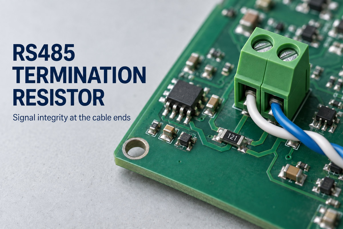
An RS485 termination resistor reduces signal reflections that can disrupt communication along a cable. In a typical two-wire bus, termination belongs at the two physical cable ends—not at every connected device.
EBest Circuit (Best Technology) combines PCB fabrication, component sourcing, and assembly for communication boards built to your approved design. For RS485 interface board production, contact sales@bestpcbs.com.
What Does an RS485 Termination Resistor Do?
It reduces the signal “echo” that returns from the end of a cable.
When a voltage transition reaches an unterminated cable end, part of its energy reflects back along the wires. That reflection can overlap the intended signal, producing ringing or a distorted transition at the receiver.
A resistor matched to the cable’s characteristic impedance absorbs energy at the endpoint, reducing the reflection. The receiver then sees a cleaner signal as it distinguishes one bit from the next.
Does RS485 Need a Terminating Resistor?
For a conventional RS485 cable bus, plan for termination at its endpoints. Leaving it out is an option for a short link only when the received signal has been shown to settle reliably before each bit is sampled.
A short bench connection may work without termination because reflections return and decay quickly. Extend the same connection across a building, and those reflections take longer to settle. The receiver may then read the signal while it is still disturbed.
Low baud rate does not automatically mean termination is unnecessary. Baud rate describes how often symbols are sent; rise time describes how quickly the voltage changes at each transition. Even a slowly communicating device can generate fast edges that produce noticeable reflections.
This is why a statement such as “no termination below a certain cable length” needs the transceiver and timing conditions alongside it. If the cable length or transceiver changes, a previously successful unterminated bench test is no longer enough to establish reliable operation.
Why Is 120 Ohms Common for RS485 Termination?
Many RS485 cables have a nominal differential characteristic impedance of 120Ω, so a 120Ω termination provides the corresponding match.
The basic relationship is:
Termination resistance ≈ cable differential characteristic impedance
Characteristic impedance is not the DC resistance of the copper wires. A cable specified as 120Ω will not necessarily read 120Ω when measured with a multimeter.
For a 120Ω cable, a 120 ohm resistor is the usual termination value. If the cable has a different specified impedance, the matching resistance changes too. A lower resistance also draws more driver current, so matching a different cable must not overload the transceiver.
Where Should an RS485 Termination Resistor Be Connected?
On a conventional two-wire, half-duplex bus, connect one resistor across A and B at each physical end of the main cable.
The connection follows three simple rules.
- Bridge the signal pair. Each resistor connects between A and B, rather than in series with either wire or from one wire to ground.
- Terminate the actual cable ends. If the cable continues beyond a device, that device is not the endpoint.
- Leave intermediate nodes unterminated. Their transceivers connect to the main cable through short branches, called stubs.
The controller’s role does not determine the resistor position. If a controller sits halfway along the cable, termination still belongs at the two cable ends.
On an endpoint PCB, place the termination close to the cable connection. Long wiring between the cable and the resistor leaves an extra path that can contribute reflections. Long stubs at intermediate devices can cause similar problems.
Four-wire connections have two separate signal pairs. In a simple point-to-point full-duplex link, each pair carries data in one direction and is commonly terminated at its receiving end. A multidrop return pair with transmitters distributed along the cable generally needs termination at both physical ends, because signals from an intermediate transmitter travel in both directions.

What Happens When RS485 Termination Is Missing or Incorrect?
Missing termination can leave the signal ringing. Too many terminators can weaken it by overloading the driver.
| Problem | What happens electrically | What you may observe |
|---|---|---|
| Required termination is missing | Reflections return from the cable end | Intermittent errors that become more apparent with longer cables or faster communication |
| Too many terminators are enabled | Parallel resistance falls and driver current rises | Reduced differential voltage or unreliable communication |
| The resistor is before the cable end | Cable remains beyond the termination point | Distorted transitions even though a resistor is installed |
| The resistance does not match the cable | Part of the signal is reflected | Ringing and reduced signal margin |
The loading effect is easy to see with 120Ω resistors. Ignoring other circuit paths, two in parallel equal 60Ω, three equal 40Ω, and four equal 30Ω. Adding a terminator at every node therefore makes the bus progressively harder to drive.
A resistance measurement alone cannot locate the problem. Two resistors installed at the wrong positions may still give approximately 60Ω across A and B.
These symptoms are not unique to termination faults. A differential waveform measurement at the receiving node can reveal ringing or low signal amplitude; communication errors alone cannot distinguish them from wiring or timing problems.
How Does RS485 Termination Differ from Biasing?
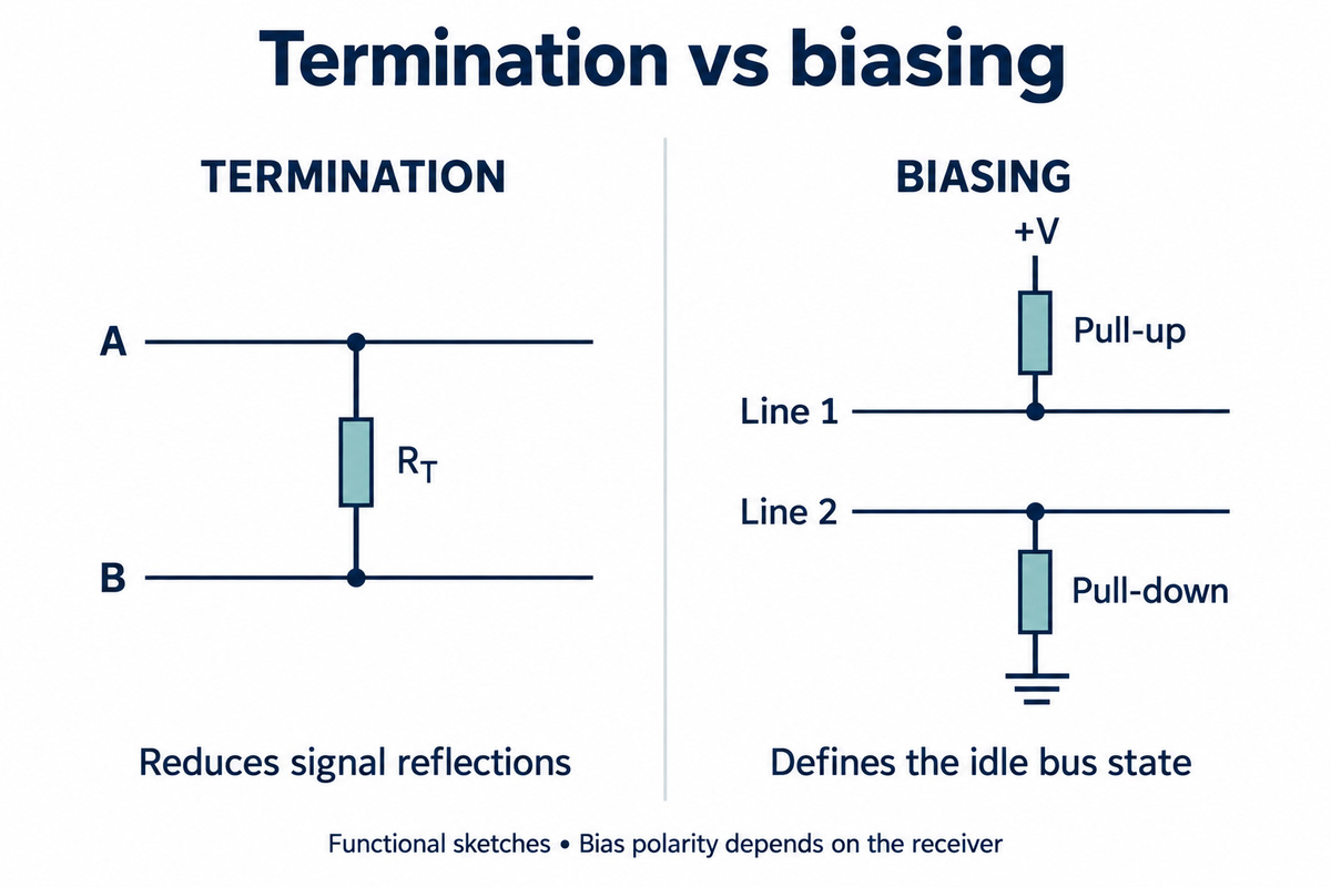
Termination reduces reflections during communication. Biasing gives the bus a defined state when no transmitter is active.
| Termination | External failsafe biasing | |
|---|---|---|
| Connection | Resistor across A and B | Pull-up and pull-down resistor network |
| Problem addressed | Signal energy reflecting from cable ends | An undriven bus leaving the receiver input near an uncertain switching level |
A resistor across A and B does not create the positive or negative differential voltage needed to establish an idle state. Biasing provides that voltage, but does not replace the endpoint termination.
Some receivers already produce a defined output on an idle bus through built-in failsafe circuitry. However, a device specified only for open-input failsafe operation does not necessarily behave the same way on an idle, terminated bus.
Termination also loads an external bias network. Bias resistor values must therefore account for the connected terminators; adding more bias networks at other nodes changes both the idle voltage and bus loading.
FAQs About the RS485 Termination Resistor
What should I measure between A and B with power off?
Two directly connected 120Ω terminators give approximately 60Ω in parallel. Cable resistance, bias networks, and connected electronics can change the reading. Disconnect power before measuring; electronically switched termination may not remain enabled when power is removed.
Can I replace two 120Ω terminators with one 60Ω resistor?
No. The two endpoint resistors may present a combined DC resistance near 60Ω, but each terminates a different cable end. A single 60Ω resistor does not provide the same impedance match at both locations.
Does a termination resistor have polarity?
An ordinary resistor has no polarity, so either end can connect to A or B. The A/B wiring between devices still needs to follow their signal definitions.
Do I need an external resistor if the device has built-in termination?
Usually not when the built-in termination is enabled and provides the required value at the endpoint. An extra external resistor would sit in parallel with it and lower the effective resistance. Check whether the built-in option is fixed, jumper-controlled, or electronically switched.
What power rating should the resistor have?
Use P = V²/R, where V is the differential voltage across the resistor. For example, 2V across 120Ω produces about 33mW of heat. Select the rating for the maximum operating dissipation with temperature derating and margin; specified fault or transient conditions may require additional capability.
For an RS485 termination resistor, correct placement matters as much as the resistance value. When your interface design is ready for PCB fabrication and assembly, contact sales@bestpcbs.com to discuss your board production requirements.