An RGB LED Board combines red, green, and blue light channels on one PCB so a controller can mix colors, dim the output, and create visual effects. Reliable performance depends less on the number of colors than on the chosen LED architecture, current control, voltage-drop margin, heat removal, and production test plan.
This guide focuses on the engineering decisions that separate a stable board from one that flickers, shifts color, overheats, or fails at the end of a long power path. It covers discrete and addressable LEDs, 5V and 12V systems, PCB layout, assembly, inspection, and the information needed for a realistic manufacturing quote.
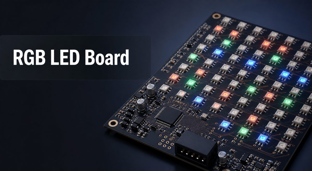
What Is an RGB LED Board?
An RGB LED board is a printed circuit assembly that controls three light-emitting channels to produce a wide range of colors. The channels may be separate dies inside one package, independent high-power LEDs, or addressable pixels with an integrated control IC.
The term can describe a small indicator board, an illuminated human-machine interface, a decorative strip, a matrix panel, or a high-output lighting module. That range matters because a compact indicator and a large display do not share the same current, thermal, routing, or test requirements.
How Does an RGB LED Board Display Work?
An RGB LED Board Display creates color by changing the relative intensity of the red, green, and blue channels. Conventional circuits use three current-controlled outputs per LED, while addressable pixels receive serial data and generate their own channel PWM internally.
The visual result depends on more than digital color values. LED binning, forward-voltage variation, driver accuracy, PWM resolution, refresh rate, diffuser geometry, ambient light, and board temperature can all change perceived brightness or color uniformity.
| Architecture | Control Method | Best Fit | Main Design Constraint |
| Discrete RGB LED | Three resistors or constant-current channels | Indicators and simple color status | Channel current and common-anode/cathode selection |
| Matrix with external driver | Multiplexing or multi-channel constant-current IC | Displays and uniform animation | Refresh rate, row current, and driver heat |
| Addressable RGB pixel | Serial data passed from pixel to pixel | Effects, signs, and modular lighting | Power distribution, data margin, and failure propagation |
| High-power RGB module | Dedicated constant-current drivers | Architectural and high-output lighting | Thermal path, current matching, and optics |
RGB LED Board 5V or RGB LED Board 12V: Which Should You Choose?
Choose 5V when the LED package or driver requires it and the board can support the resulting current; choose 12V when the selected LED architecture is designed for 12V and lower distribution current is important. Voltage is not interchangeable, so the LED and driver datasheets must define the final rail.
For equal electrical power, a 12V feed carries less current than a 5V feed, which reduces connector and trace loss. However, many 12V addressable products group LEDs or use internal regulation, changing pixel granularity and efficiency. A 5V board may offer finer pixel control but need wider copper, more injection points, and stronger connectors.
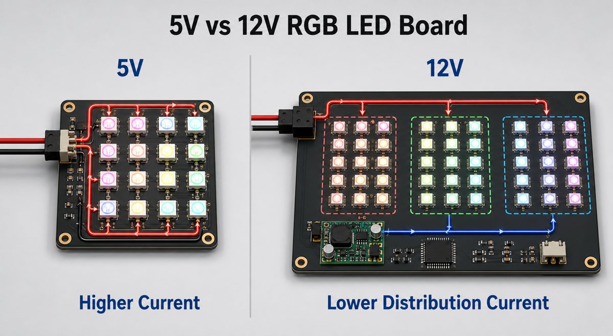
| Decision Point | 5V Board | 12V Board |
| Distribution current at equal power | Higher | Lower |
| Typical control granularity | Often one addressable LED package | May control grouped LEDs, depending on the part |
| Power-path priority | Wide copper and frequent injection | Input protection and local voltage conversion where needed |
| Selection rule | Use only the voltage and topology specified for the selected LED and driver | |
For a practical 5V addressable example, see our guide to a rigid 5V addressable RGB strip.
How Should Power and Current Be Calculated?
Calculate the worst-case current from the LED or driver datasheet, then verify copper loss, connector rating, supply margin, and temperature at the intended duty cycle. For addressable pixels, a conservative first estimate is the pixel count multiplied by the maximum full-white current per pixel; the validated design should use the actual selected part.
Older 5V addressable pixels are sometimes budgeted at up to 60mA each at full white, but newer devices can differ substantially. Do not copy that value into a production specification without checking the exact package. The same caution applies to brightness-limited firmware: software limits are useful, but the hardware should still fail safely.
- Estimate worst-case LED, driver, regulator, and controller current.
- Calculate path drop with ΔV = I × R for traces, vias, cables, and connectors.
- Check the lowest voltage at the farthest LED under maximum load.
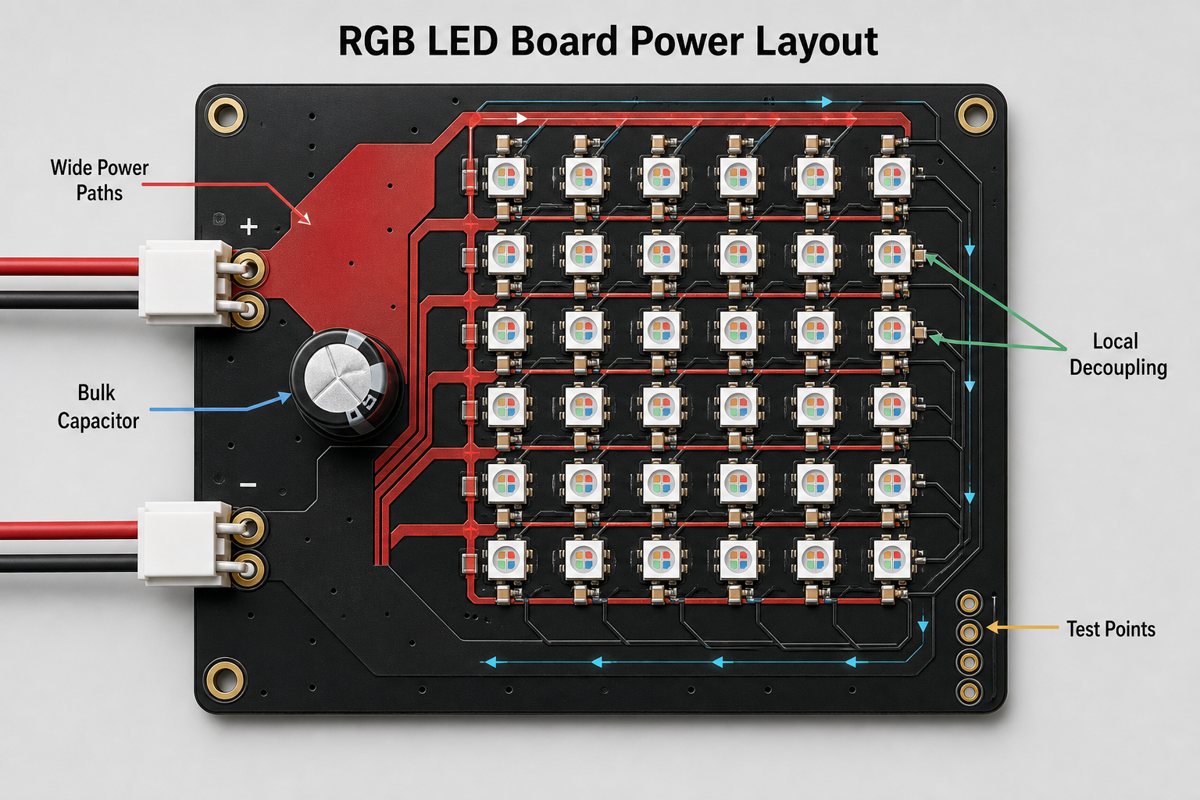
- Provide bulk capacitance at the input and local decoupling near switching loads.
- Add power-injection points when one feed cannot hold the voltage window.
- Measure full-white current and board temperature on the assembled prototype.
How Should the Driver and Control Interface Be Selected?
Select the driver from the required channel count, current accuracy, PWM resolution, refresh behavior, communication interface, and thermal limit. A simple indicator may need three transistor or current-sink channels, while a matrix may benefit from an I2C or SPI constant-current driver with independent color and brightness control.
RGB dimming usually uses three PWM channels. Dedicated RGB drivers can add current matching, phase-shifted PWM, fault reporting, and lower microcontroller workload. Addressable LEDs reduce driver count but make logic thresholds, data timing, chain length, and power sequencing part of the board-level design.
A 3.3V controller does not automatically provide a reliable logic-high level to every 5V pixel. Verify the input threshold across supply and temperature, and add a logic-level shifter when the noise margin is insufficient. For many addressable designs, a 300–500Ω series resistor close to the first data input and a 500–1000µF bulk capacitor near the power entry are useful starting practices, subject to the selected device guidance.
Which PCB Layout Rules Improve Color Stability and EMC?
Stable color requires low-impedance power and ground paths, controlled switching loops, short data routes, and consistent local decoupling. A board can pass a low-brightness bench test yet flicker at full white when return-path voltage or simultaneous switching noise shifts the logic reference.
- Use continuous ground where possible and avoid routing data across return-path gaps.
- Place the driver, level shifter, and input protection close to the signals they serve.
- Keep each decoupling capacitor close to its LED or driver power pins.
- Use copper pours, parallel feeds, and sufficient vias for high-current distribution.
- Separate noisy switching nodes from sensitive data, clock, and analog reference paths.
- Add accessible test points for input power, ground, data, clock, and key driver rails.
For broader component placement and routing context, our earlier RGB LED PCB design article provides a useful starting reference.
How Should Heat Be Managed?
Manage heat by converting LED and driver losses into a realistic power map, then giving that heat a low-resistance path into copper, the enclosure, airflow, or a heat-spreading substrate. RGB boards can heat unevenly because the three color dies have different forward voltages and because animation does not load every channel equally.
FR-4 is appropriate for many indicators, decorative modules, and moderate-power displays. High-output lighting may need thicker copper, thermal vias, a metal-backed board, interface material, or an enclosure heat sink. The choice should follow measured junction or board temperature rather than an automatic material rule.
When the LED power density is high, review the thermal options in our LED PCB manufacturing and thermal design guide.
What Manufacturing and Assembly Checks Matter?
Manufacturing control should protect LED orientation, solder quality, optical uniformity, and the high-current power path. RGB packages can look symmetrical while having a strict pin-one or data-direction requirement, so assembly drawings and silkscreen must make orientation unambiguous.
- Confirm LED polarity, pin-one, data-in/data-out direction, and common-anode or common-cathode selection.
- Review stencil apertures for exposed pads, thermal pads, and fine-pitch driver packages.
- Control board flatness when lenses, diffusers, or light guides need consistent spacing.
- Use AOI for component presence, orientation, and solder-joint screening.
- Use X-ray where a hidden thermal pad, QFN, BGA, or bottom-terminated joint requires it.
- Protect LED optical surfaces from contamination, scratches, and incompatible cleaning residues.
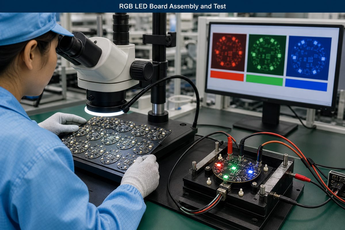
A complete LED module assembly process should connect PCB inspection with optical and functional verification rather than treating solder quality as the only acceptance criterion.
How Should an RGB LED Board Be Tested?
Test each color channel independently before running mixed-color patterns, then repeat the test at the lowest and highest specified input voltage. This sequence separates assembly defects from firmware, color-order, power-distribution, and thermal problems.
- Inspect orientation, solder joints, bridges, contamination, and damaged LED packages.
- Check resistance or current-limited power-up before applying full supply current.
- Light red, green, and blue separately to detect swapped or open channels.
- Run black, primary colors, white, gradients, and fast transitions.
- Measure input current, far-end voltage, connector rise, and hot spots at maximum intended duty.
- Test communication margin, startup behavior, reset behavior, and power-cycle recovery.
- Use a fixture or camera method when brightness and color uniformity are acceptance requirements.
The functional test specification should define allowable dead pixels, channel failures, brightness variation, current limits, and cosmetic defects. A vague instruction such as “lights OK” is not repeatable enough for production.
What Affects RGB LED Board Price?
RGB LED Board Price is driven mainly by LED count and grade, driver complexity, PCB size and copper, assembly density, thermal structure, optical requirements, and functional test coverage. A low-cost board can become expensive if color uniformity, high brightness, waterproofing, tight binning, or individual-pixel testing is added late.
| Cost Driver | Why It Changes Cost |
| LED type and binning | Affects component price, color consistency, brightness, and sourcing risk |
| Board area and copper | Changes material use, current capacity, panel utilization, and thermal behavior |
| Driver and control circuit | Adds ICs, passives, programming, routing density, and validation effort |
| Assembly and inspection | Depends on package pitch, bottom-terminated joints, AOI, X-ray, and rework access |
| Functional and optical test | Fixture time and acceptance criteria increase with pixel count and uniformity requirements |
For a useful comparison, send the same controlled file set to each manufacturer. Otherwise, one quote may include programmed parts, optical testing, or cable assembly while another covers only bare PCB fabrication.
FAQ About RGB LED Boards
- Can a 3.3V microcontroller control a 5V RGB LED board?
- It can when the LED or driver recognizes the 3.3V logic-high level under all operating conditions. Many 5V addressable LEDs need a logic-level shifter for reliable margin, so the component datasheet and worst-case voltage thresholds should decide the interface.
- Does every RGB LED need a resistor?
- Discrete RGB LEDs normally need current limiting for each color channel unless a constant-current driver provides it. Addressable RGB packages usually integrate their own driver, but they still need correct local decoupling and may need a series resistor on the incoming data line.
- Why does an RGB LED board show the wrong color?
- Wrong color usually comes from an incorrect channel order, a common-anode versus common-cathode mismatch, weak ground reference, voltage drop, a damaged channel, or the wrong data protocol. Testing red, green, and blue separately helps isolate the fault.
- Is FR-4 suitable for an RGB LED board?
- FR-4 is suitable for indicators, decorative panels, and many moderate-power RGB assemblies when copper area and airflow control temperature. High-power or tightly enclosed lighting may need a metal-core PCB or another thermal path after a verified thermal analysis.
- What files are needed to quote a custom RGB LED board?
- A useful quote package includes Gerber and drill files, BOM, pick-and-place data, assembly drawings, LED and driver datasheets, input voltage, LED count, dimensions, quantities, color or brightness requirements, and the required functional test.
How Can EBest Circuit Support Your RGB LED Board Project?
At EBest Circuit, we support PCB design review, prototype fabrication, component sourcing, PCB assembly, AOI, X-ray where applicable, and functional testing for custom LED electronics. We can review the power path, LED orientation, driver package, thermal structure, panelization, assembly data, and production test requirements before volume build.
Send your Gerber files, BOM, pick-and-place data, LED and driver datasheets, input voltage, dimensions, quantity, and test requirements to sales@bestpcbs.com. We will use that information to prepare a manufacturing review and quotation for your RGB LED Board.