Before changing a capacitor to fix an apparent power-rail spike, capture the same rail with a short probe return and measure the setup’s own noise. If the spike changes when you move the probe loop but the board and load stay the same, investigate pickup first. If the measured ripple is close to the instrument floor, report the result as unresolved until a suitable measurement can separate them.
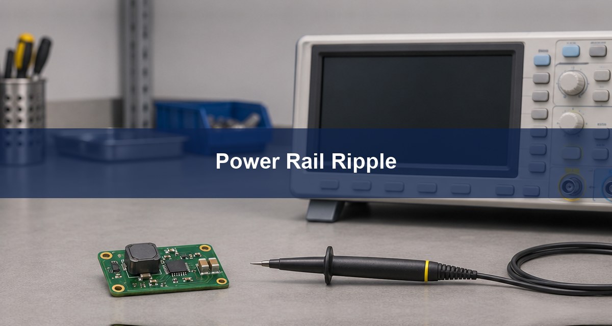
Power Rail Ripple: Identify the Size and Time Scale
Ripple is a periodic variation riding on a DC rail. A switched converter can also show fast switching spikes, a slower burst envelope and unrelated broadband noise. These features need different measurement windows. First ask whether the requirement limits periodic ripple, all noise within a specified bandwidth, or movement during a load change.
For this guide, consider an earth-compatible 3.3 V rail on a low-voltage converter board. The task is to judge its running ripple at the load, not probe its switching node or a mains-referenced circuit. The Best Technology DC-DC converter test guide covers the separate startup, regulation and transient checks.
Power Supply Ripple Measurement: Fix the Test Boundary
Choose a rail-to-local-return point based on the product requirement. The converter output capacitor and the load pins can see different ripple because current flows through traces and vias. If both matter, record both as separate measurements. Hold input, load, operating mode and temperature constant during probe comparisons.
Save the coupling, bandwidth, attenuation, sample rate, acquisition mode and duration with the raw waveform. Use a window long enough to include the slow behavior of interest without sacrificing the sampling needed for fast edges. A different burst mode, scope setting or measurement location can change the result even when the board is unchanged.
Oscilloscope Ground Spring: Test for Pickup
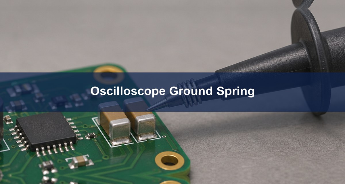
A long return lead adds loop area and inductance. It can pick up fields from the switch node or create ringing in the measurement. Compare the original setup with an approved low-loop-area connection at the same pads. TI SNVA871 includes an example of probe-connection effects. A smaller spike after the swap does not prove that all remaining noise belongs to the board.
Check the return potential before connecting a ground spring. On an earth-referenced oscilloscope the probe ground can tie the circuit to protective earth. Never defeat protective earth or attach the return to a floating or switching node without a rated, appropriate measurement arrangement.
Power Rail Probe: Choose the Setup for the Signal
Use a probe with adequate offset, sensitivity, loading and bandwidth for the rail. A large attenuation ratio can make small signals harder to resolve. A direct 50 Ω termination is not a default: it can draw current, shift the DC rail or exceed the input rating. Follow the probe and instrument documentation.
| Setup | Use when | Verify first |
|---|---|---|
| Passive probe with local spring | The return is earth-compatible and signals are comfortably above the setup floor. | Loop area, attenuation and tip position. |
| Dedicated rail probe | Small AC variation rides on DC and offset or loading limits the passive setup. | Offset and input limits, noise floor and loading. |
| Rated differential or isolated arrangement | The reference cannot safely be tied to earth. | Common-mode range, ratings and rejection at frequency. |
Oscilloscope Noise Floor: Save Two Control Traces
First capture an input-referred baseline with the probe input connected to its return according to the instrument’s instructions, away from the switching field. Use the same vertical scale, coupling and bandwidth as the live trace. Then, where the fixture and equipment allow it safely, capture a local same-node null near the operating board with both contacts on the permitted reference. It can reveal pickup present near the board even when no intended differential signal is applied.
Do not subtract peak-to-peak values. As a separate RMS example, a 4.0 mV RMS reading and 3.0 mV RMS baseline would imply about 2.65 mV RMS for uncorrelated contributions with the same bandwidth, using √(4² − 3²). This cannot remove coherent switching pickup, recover an overlapped signal reliably or justify release near a limit. These are assumed readings. A lower-noise setup is preferable when the difference is small. See Keysight’s power-rail measurement note.
Oscilloscope Bandwidth Limit: Report Two Captures When Needed
Use the bandwidth specified by the acceptance requirement. If the requirement says 20 MHz, make the comparable capture at that setting. A wider-band screenshot can help investigate spikes but does not have the same pass/fail limit. Conversely, a bandwidth-limited trace cannot establish that troublesome high-frequency content is absent.
AC vs DC Coupling Oscilloscope Settings for Ripple
AC coupling removes DC, but the input high-pass response can distort slow envelope changes and load droop. DC coupling with suitable offset preserves the DC level and slow variation if the signal fits the input range. For this 3.3 V rail, record both the steady ripple view and a DC-coupled view if the question includes burst behavior or absolute rail limits.
Peak to Peak Noise: Decide What Can Be Reported
Peak-to-peak is the difference between the largest and smallest captured values. A longer acquisition can include a rare transient that a shorter one misses. Make a comparison with the same capture length and bandwidth, then keep unusual events as separate evidence. Report RMS and peak-to-peak separately, not as interchangeable values.
| Observation | Next check | What to report |
|---|---|---|
| Spike tracks probe orientation or appears on the local null. | Reduce loop area and repeat the controls. | Pickup suspected; no board conclusion yet. |
| Live trace nearly matches the setup baseline. | Improve sensitivity or use a lower-noise measurement chain. | Not resolved at the current settings. |
| Feature repeats with verified connections and tracks converter operation. | Compare against the specified test condition and limit. | Report waveform, settings and evidence of a repeatable board feature. |
FAQ
Is a triangular waveform required for a buck converter?
No. Operating mode, output network and measurement settings can change its shape.
What is the first check when a spike looks too large?
Check the return geometry and capture a suitable null before changing the board.
Can I subtract the baseline peak-to-peak value?
No. The maxima and minima generally do not occur at the same times.
Is 20 MHz the right bandwidth for every rail?
No. Match the product or instrumented test requirement, and label any wider diagnostic capture separately.
Why does the ripple disappear with AC coupling?
Slow variation can be filtered out. Verify the lower cutoff and use a supported DC-coupled setup if needed.
Can a multimeter establish absence of ripple?
Not by itself. Its measurement bandwidth and function may not capture the events you need to measure.
Should I measure at the converter or at the load?
Use the specified point. If both matter, label and compare them separately.
What should I put in a ripple test report?
Include the test points, load and mode, probe connection, settings, baseline, waveform and limits.
Discuss Your PCB Power Integrity Review
For a Best Technology fabrication or assembly discussion, send the board revision, stackup, probe-point photos and test requirements to sales@bestpcbs.com. Include both the live and control traces if you are comparing a layout change.