PCB spacers are small mechanical supports used to keep a PCB at a fixed distance from an enclosure, chassis, panel, heatsink or another board. They help prevent short circuits, reduce board bending, protect solder joints and keep components away from nearby surfaces.
In PCB assembly, these parts should not be treated as simple accessories. The wrong height, material, thread size or mounting position can cause PCB stress, enclosure conflict, poor connector alignment or electrical failure. This guide explains how board spacing hardware works and how to choose it for reliable PCBA production.
What Are PCB Spacers?
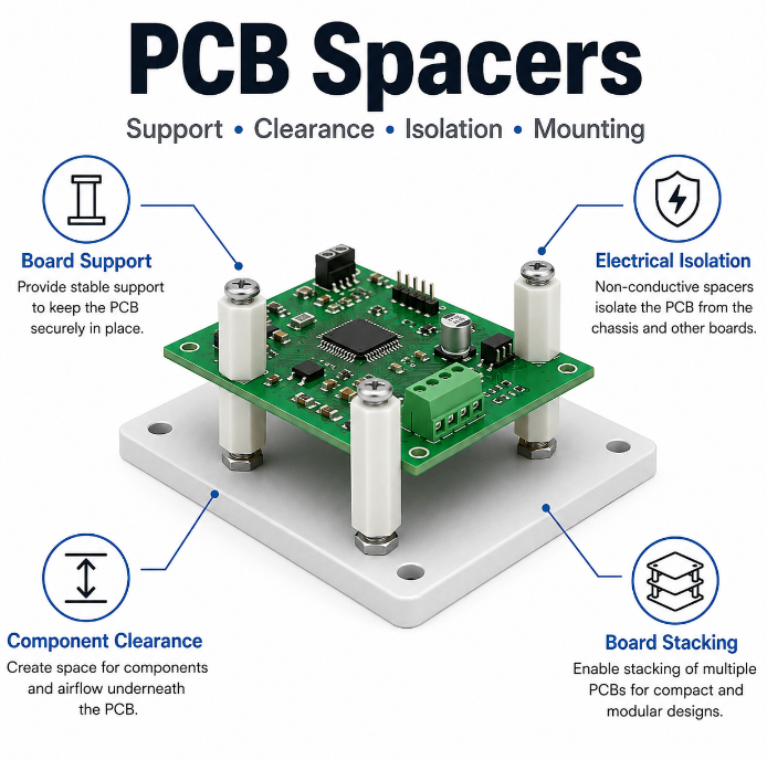
These spacers are fixed-height support parts placed between a PCB and another surface. Their main role is to create a stable gap so the board does not touch a metal shell, plastic enclosure, display module, power plate or another circuit board.
They may look like small cylinders, sleeves, posts or hex-shaped supports. Some are hollow and used with screws. Some are threaded, snap-in or adhesive-backed. Their structure is simple, but their effect on clearance, strength and assembly stability is very important.
You may also see related names such as PCB board spacers, PCB mounting spacers, PCB spacers and supports, PCB standoffs and spacers, and PCB component spacers.
What Are PCB Spacers Used For in PCB Assembly?
These parts are used to support, separate, align and protect the PCB during final assembly. They keep the board in the correct mechanical position and reduce the risk of electrical contact with nearby conductive parts.
Common uses include:
- Board support: keeps the PCB flat during fastening and operation.
- Electrical isolation: prevents solder joints and copper pads from touching metal.
- Component clearance: protects bottom-side components and solder leads.
- Board stacking: keeps two PCB boards at a controlled distance.
- Enclosure alignment: helps connectors, LEDs, switches and buttons match openings.
- Air gap control: leaves space around hot parts for better heat movement.
For this reason, these supports are widely used in prototypes, consumer electronics, industrial control products, medical devices, power modules and communication equipment.
Why Are PCB Spacers Necessary for Circuit Boards?
These supports are necessary because a PCB needs safe distance and stable mechanical support. Without controlled spacing, the board may touch an enclosure, bend under screw pressure or move during shipping and use.
They also protect mounting holes. If screws are tightened against an unsupported PCB, the board can flex and create stress around copper pads, vias and solder joints. Over time, this may lead to cracked joints, lifted pads or intermittent failure.
In power products, LED modules and industrial electronics, spacing also affects safety. A proper gap helps protect clearance, airflow and component life. Therefore, board supports should be reviewed together with the PCB layout, enclosure design and PCBA assembly process.
What Problems Can Wrong PCB Spacers Cause?
Wrong spacer selection can cause mechanical stress, electrical contact, assembly delay and long-term reliability problems. These failures often appear after enclosure assembly, so early design review is important.
- Problem: spacer height is too low.
The PCB may touch the enclosure or bottom-side components may be compressed.
Solution: measure the tallest underside component and add safe mechanical clearance. - Problem: spacer height is too high.
Connectors, LEDs, buttons or displays may not align with the product shell.
Solution: check spacer height with the enclosure 3D drawing and front panel design. - Problem: metal spacer touches copper.
A short circuit may occur if the mounting hole is not designed for grounding.
Solution: add copper keepout or clearly define grounded mounting holes. - Problem: too few support points.
Large PCB panels may sag, vibrate or crack near heavy components.
Solution: add support near corners, connectors, transformers, heatsinks and long board areas. - Problem: screws are over-tightened.
The PCB can bend or crack around mounting holes.
Solution: use controlled tightening, proper screw length and flat support surfaces.
The safest method is to check height, material, support quantity and layout position before PCB fabrication.
What Are the Main Types of PCB Spacers?
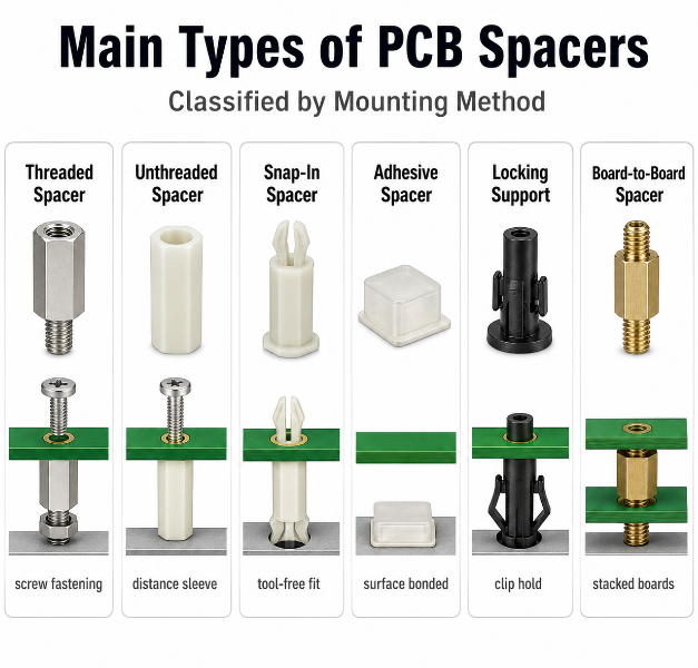
The main types of spacer hardware should be classified by mounting method. This is the clearest standard because the mounting method directly affects assembly speed, strength, repair access and product reliability.
| Type | Mounting | Feature | Best Use |
|---|---|---|---|
| Threaded spacer | Screw fastening | Strong and reusable | Production PCBA and metal enclosures |
| Unthreaded spacer | Screw passes through | Simple distance sleeve | Low-cost board spacing |
| Snap-in spacer | Push into PCB hole | Fast tool-free assembly | Plastic housings and light boards |
| Adhesive spacer | Bonded to surface | No drilling required | Prototypes and light-load products |
| Locking support | Clip or latch | Holds PCB without screws | Fast assembly and serviceable products |
| Board-to-board spacer | Between two PCB boards | Fixed stacking distance | Stacked modules and daughter boards |
For mass production, threaded PCB spacers and snap-in PCB spacers are often easier to control. Adhesive spacers are convenient, but they should be avoided in high-temperature, high-vibration or heavy-load products.
What Materials Are Used for PCB Spacers?
These supports are commonly made from nylon, brass, aluminum, stainless steel and ceramic. Material selection should follow the same standard: electrical behavior, strength, weight, temperature resistance and application environment.
| Material | Electrical | Strength | Weight | Best Use |
|---|---|---|---|---|
| Nylon | Insulating | Medium | Light | General electronic assemblies |
| Brass | Conductive | High | Medium | Grounding and strong threaded mounting |
| Aluminum | Conductive | Medium to high | Light | Lightweight metal support |
| Stainless steel | Conductive | Very high | Heavy | Harsh or high-load environments |
| Ceramic | Insulating | Medium | Medium | High-temperature insulation |
Nylon PCB spacers are widely used when insulation and low weight matter. Brass PCB spacers are suitable for strong fastening and grounding. Aluminum PCB spacers are useful when the design needs metal support with lower weight.
For regulated products, material documents should be checked, especially for RoHS, flame rating, plating and operating temperature.
Nylon vs Brass vs Aluminum PCB Spacers: Which Is Better?
Nylon, brass and aluminum versions are used for different design needs. The best choice depends on insulation, grounding, strength, weight and working environment.
| Item | Nylon | Brass | Aluminum |
|---|---|---|---|
| Electrical behavior | Insulating | Conductive | Conductive |
| Mechanical strength | Medium | High | Medium to high |
| Weight | Light | Medium | Light |
| Grounding use | Not suitable | Suitable | Suitable |
| Heat resistance | Medium, grade-dependent | Good | Good |
| Corrosion resistance | Good in normal use | Often plated | Good, finish-dependent |
| Cost level | Low to medium | Medium | Medium |
| Main advantage | Insulation and light weight | Strength and grounding | Lightweight metal support |
| Main limitation | Lower strength than metal | Can cause shorts if misused | Conductive and easier to scratch |
| Suitable products | General electronics, plastic enclosures | Industrial controls, metal chassis | Lightweight devices, compact modules |
The practical selection rule is simple: use nylon for insulation, brass for strength and grounding, and aluminum for lightweight metal support.
What Plastic Is Best for PCB Spacers?
The best plastic for board spacers depends on temperature, load, insulation, flame rating and cost. For many standard electronic products, nylon is the most common choice because it is light, insulating and easy to produce.
For higher thermal or flame requirements, the material grade should be reviewed carefully. Flame-rated nylon, glass-filled nylon, PBT, PPS or other engineering polymers may be selected when the product must handle higher heat, stronger load or stricter safety requirements.
In general, nylon PCB spacers are suitable for common PCBA products, while higher-grade materials should be considered for power electronics, automotive electronics, industrial equipment or products used near hot components.
How to Choose the Right PCB Spacer Height and Size?
Choose PCB spacer height and size by checking clearance, hole fit, screw size, board thickness, enclosure space and assembly tolerance. The spacer must support the board without forcing the PCB to bend.
- Check bottom-side clearance.
Measure the tallest solder joint, IC, connector pin or bottom-side component. Add enough gap so nothing touches the enclosure. - Match the mounting hole.
The spacer post, screw or snap-in feature must fit the PCB hole without cracking the laminate or becoming loose. - Confirm screw and thread size.
Common small assemblies may use M2, M2.5 or M3 hardware. The screw, spacer and enclosure boss must match. - Review spacer outer diameter.
The spacer body should not touch nearby components, test points, copper traces or solder pads. - Check board thickness.
PCB thickness affects screw length, snap-in retention and clamping force. - Control spacer height tolerance.
Uneven height may twist the board after fastening. This is more critical for stacked boards and large PCB panels. - Consider load and service use.
Heavy connectors, cables, displays and heatsinks may need stronger spacers or more support points.
Before bulk production, test samples with the real PCB, enclosure and screw hardware.
How Many PCB Spacers Does a Circuit Board Need?
The number of support points depends on board size, board thickness, component weight, vibration level and connector force. A small board may use two to four supports, while a larger PCB may need corner support plus middle support.
More supports are needed when the PCB carries transformers, relays, heatsinks, large capacitors, cables or high-insertion-force connectors. These parts create bending stress during operation and service.
Do not add spacers randomly. Each support point should match a mounting hole, enclosure boss or board-to-board structure. The goal is even support and stable assembly, not excessive hardware.
How Should PCB Spacers Be Placed in PCB Layout?
Spacer hardware should be placed where it provides stable support, safe clearance and easy assembly access. Placement should be reviewed during PCB layout, not after the enclosure is finished.
- Place support near board corners.
Corner support keeps the PCB stable and reduces movement during fastening. - Add support near heavy parts.
Transformers, heatsinks, large capacitors and relays need nearby support to reduce board bending. - Support connector areas.
USB ports, terminal blocks and pin headers create insertion force. Add support near these zones. - Protect high-voltage areas.
Keep spacers away from unsafe copper areas unless the mounting hole is designed for grounding. - Leave room for tools.
Screwdrivers, nuts and washers need working space around the mounting point. - Avoid component conflict.
Spacer heads and screws should not interfere with tall components, cables or test fixtures. - Use center support for large PCB boards.
Long or thin boards may sag if only the corners are supported. - Match enclosure bosses.
Mounting holes should align with the real enclosure structure to avoid forced assembly.
If metal spacers are used, mark grounded and isolated mounting holes clearly in the PCB layout.
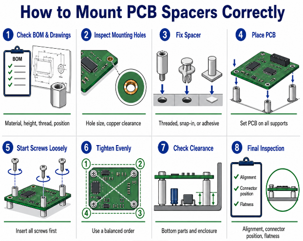
How to Mount PCB Spacers Correctly?
Mount these supports through a controlled process so the PCB stays flat, aligned and free from stress. The process should confirm both mechanical fit and electrical safety.
Step 1: Check the BOM and drawings.
Confirm spacer material, height, thread, screw size, quantity and mounting position against the PCB drawing and enclosure drawing.
Step 2: Inspect the PCB mounting holes.
Check hole size, annular ring, copper clearance and nearby components. The spacer should not force the hole or touch exposed copper unless grounding is intended.
Step 3: Fix the spacer to the enclosure or lower board.
Install threaded or snap-in spacers in the correct position. For adhesive spacers, clean the surface and confirm bonding area.
Step 4: Place the PCB gently.
The PCB should sit flat on all support points. Do not press the board down to force hole alignment.
Step 5: Insert screws loosely first.
Start all screws before full tightening. This prevents one side from being pulled down too early.
Step 6: Tighten in a balanced order.
Tighten screws gradually and evenly. Avoid excessive torque around mounting holes.
Step 7: Check final clearance.
Confirm bottom components, solder joints, cables and enclosure walls have enough space.
Step 8: Inspect alignment and stability.
Check connector position, button height, LED window alignment and board flatness before final assembly approval.
How Do PCB Spacers Affect PCB Assembly?
These parts affect PCB assembly by controlling fit, board flatness, screw force, component clearance and final product alignment. A spacer that looks correct in a catalog may still cause problems during real PCBA assembly.
If a spacer is too close to a tall capacitor, connector or cable, fastening becomes difficult. If spacer height varies, the board may twist after screw tightening. If the spacer blocks a test point, programming header or label, testing and rework become slower.
For stable production, these supports should be checked with the enclosure, fixture, test access and final inspection process. This helps reduce assembly delay, rework and field failure.
What Are Common Mistakes When Using PCB Spacers?
Common mistakes come from choosing spacer hardware without checking real assembly conditions. Each mistake should be corrected before PCB fabrication or bulk PCBA production.
- Mistake: choosing by height only.
Height is important, but material, thread, strength and clearance also matter.
Solution: review spacer selection with the PCB, enclosure and screw set. - Mistake: using metal spacers near exposed copper.
This can create short circuits.
Solution: add copper keepout or use insulating spacers. - Mistake: placing spacers too close to components.
Tools may not reach the screw position.
Solution: reserve tool access around every mounting point. - Mistake: using too few supports.
The board may sag during vibration or cable insertion.
Solution: add support near heavy parts and long board areas. - Mistake: ignoring plastic temperature limits.
Some plastic spacers may deform near hot components.
Solution: confirm material temperature rating and flame class. - Mistake: over-tightening screws.
The PCB may bend or crack.
Solution: use proper screw length, flat support and controlled tightening. - Mistake: approving parts without sample assembly.
Catalog dimensions may not show real fit issues.
Solution: test sample spacers before bulk orders.
The best prevention is early mechanical review before PCB manufacturing and PCBA assembly.
Where Are PCB Spacers Commonly Used?
These supports are used wherever a circuit board must be supported, separated, insulated or stacked. They appear in simple electronic devices and complex industrial products.
Common applications include:
- Consumer electronics: displays, smart devices, control panels and small modules.
- Industrial control: PLC boards, relay modules, sensors and automation systems.
- Power electronics: power supplies, LED drivers, chargers and inverter boards.
- Communication devices: routers, gateways, RF modules and network equipment.
- Medical electronics: monitoring devices, diagnostic equipment and control boards.
- Automotive electronics: lighting modules, control units and sensor boards.
- Test equipment: fixture boards, measurement modules and removable test PCBs.
- Prototype builds: quick assembly using removable PCB board spacers.
In these products, these supports improve assembly stability, protect electrical clearance and support long-term product reliability.

FAQs About PCB Spacers
Q1: Are PCB spacers included in a PCB BOM?
A1: Yes, they should be listed in the BOM when they are part of the final assembly. The BOM should include material, height, thread size, quantity and supplier part number. This prevents purchasing errors and keeps PCBA assembly consistent.
Q2: What thread sizes are common for PCB spacers?
A2: Common thread sizes include M2, M2.5 and M3 for many electronic products. Larger boards may use bigger hardware. The correct thread depends on PCB hole size, enclosure boss design, board weight and assembly strength.
Q3: Can washers replace PCB spacers?
A3: Washers can help spread screw pressure or make small adjustments, but they cannot replace fixed-height board supports. A washer does not provide stable vertical support. For proper board mounting, use spacers with controlled height.
Q4: Should PCB mounting holes have copper around them?
A4: Copper around mounting holes depends on the design. If the hole is used for grounding, copper and vias may be added. If it must stay isolated, copper should be removed around the hole. The layout should clearly define grounded or isolated mounting holes.
Q5: Can PCB spacers affect EMI performance?
A5: Yes, metal spacers can support chassis grounding and shielding paths when designed correctly. If used incorrectly, they may create unwanted current paths. EMI-sensitive products should define ground points, screw contact and chassis connection during layout.
Q6: Are nylon PCB spacers suitable for high-temperature products?
A6: Standard nylon may not be suitable near high-heat parts. Temperature rating depends on the exact material grade. For power products or hot zones, use flame-rated or higher-temperature material and confirm thermal margin before production.
Q7: Can PCB spacers be reused after disassembly?
A7: Threaded metal spacers can often be reused if threads are not damaged. Snap-in and adhesive spacers may lose holding force after removal. For serviceable products, threaded spacers are usually better because they offer repeatable fastening.
Q8: What tolerance matters most for PCB spacers?
A8: Height tolerance is very important because uneven spacer height can twist the PCB. Thread quality and outer diameter also matter for fit. For stacked boards, tolerance should be controlled more tightly to maintain level board spacing.
Q9: Do PCB spacers need flame rating?
A9: Flame rating is important for products with safety requirements, power circuits or enclosed plastic structures. Many projects check UL 94 class for non-metallic parts. If the spacer is close to heat or power components, confirm flame rating and material certificate.
Q10: Are adhesive PCB spacers good for mass production?
A10: Adhesive spacers are useful for light-load products and prototypes. They are less suitable for vibration, high heat or heavy boards. For mass production, threaded or snap-in designs usually provide better repeatability and stronger support.
Q11: Can PCB spacers be customized?
A11: Yes, custom spacers can be made for special height, thread, material, shape or enclosure structure. Custom parts are useful for stacked boards, sealed products or unusual mechanical gaps. Before ordering, confirm drawing tolerance and sample assembly.
Q12: What should be inspected after spacer installation?
A12: Inspect board flatness, screw tightness, component clearance, connector alignment and electrical isolation. Also check whether the PCB is twisted or under stress. A simple final inspection can prevent assembly rework and field failure.
Q13: Can PCB spacers support heavy connectors?
A13: They can help, but the spacer must be placed near the connector area. Heavy plugs and terminal blocks create insertion and pulling force. Add nearby support points so the PCB does not bend during cable installation or product service.
Q14: How should PCB spacers be packed for production use?
A14: Production packing should prevent mixed sizes, damaged threads and material confusion. Labels should show part number, size, material and batch information. For PCBA assembly, organized packing helps reduce wrong-part installation on the line.
Conclusion
PCB spacers may be small, but they directly affect PCBA safety, board support, component clearance, airflow, enclosure fit and long-term reliability. A good spacer choice should match the PCB layout, enclosure structure, material requirement, mounting method and production process.
If you need PCB manufacturing or PCBA assembly support, EBest Circuit can help review mounting holes, spacer placement, enclosure clearance and final assembly risks before production. For custom PCBA service, prototype assembly or bulk production, contact us for a quotation: sales@bestpcbs.com.