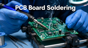
Reliable PCB board soldering depends on controlled heat, compatible materials, and clean joining surfaces. Too little heat prevents proper wetting, while prolonged contact can damage the pad or laminate.
This guide explains the main soldering methods and the temperatures used for each process. It also covers hand soldering, cleaning, common defects, and the point at which production equipment becomes the better choice.
What Is PCB Board Soldering?
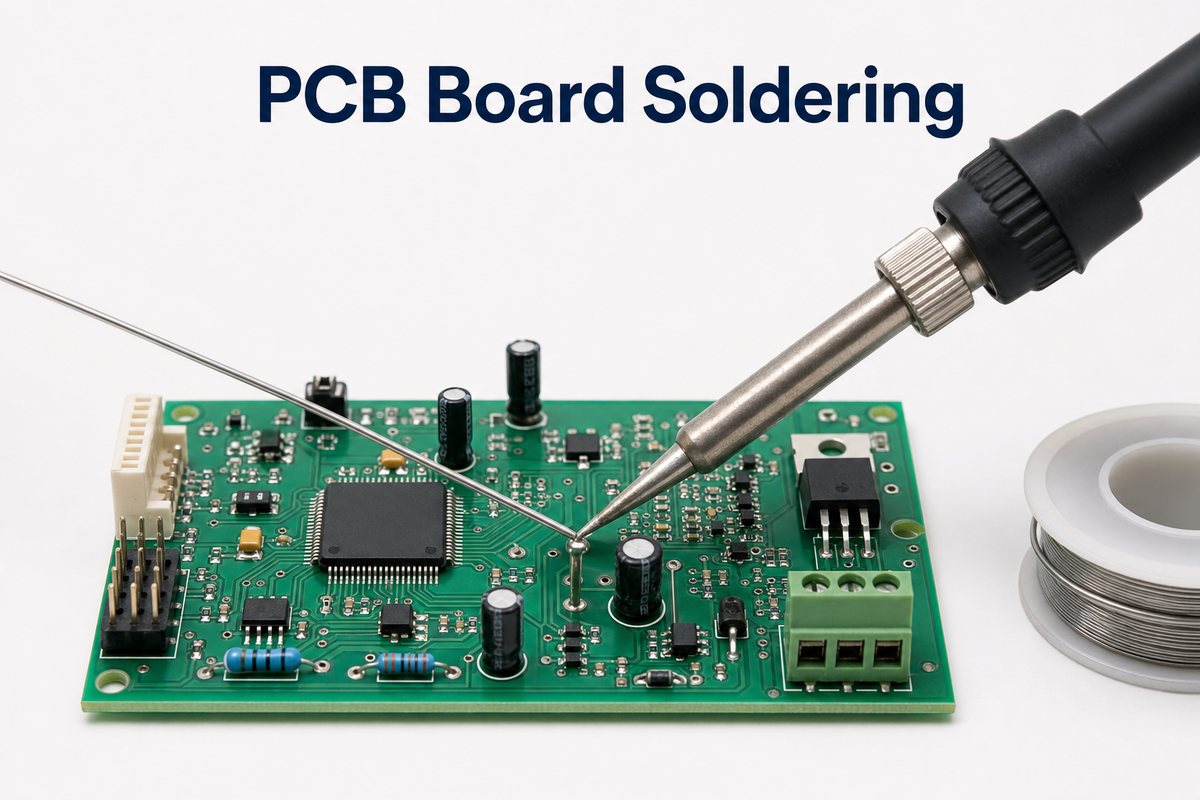
PCB board soldering is the process of using solder to attach an electronic component to a printed circuit board. It creates an electrical path for current and a mechanical bond that holds the component in place.
The component termination is the metal lead or contact that joins the board, while the PCB pad is the exposed copper area beneath it. During soldering, both surfaces are heated together and flux removes light oxidation, allowing solder to spread across both metals. This spreading action is called wetting and shows that the solder has bonded to the surfaces.
Types of PCB Soldering
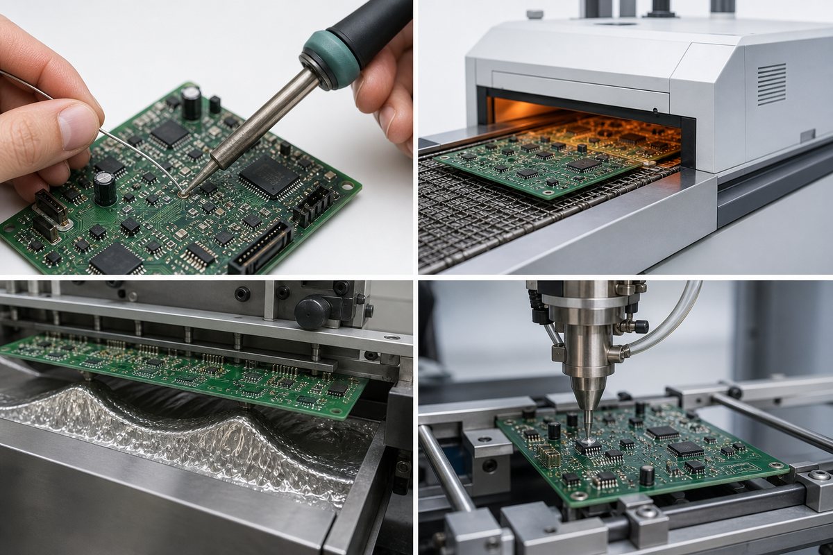
The main types of PCB soldering are manual, reflow, wave, and selective soldering. The right method depends mainly on the components and the number of boards being assembled.
| Method | Typical Application | Solder Form |
| Manual soldering | Prototypes, wires, through-hole parts, and rework | Flux-cored solder wire |
| Reflow soldering | Surface-mount components on assembled panels | Solder paste |
| Wave soldering | Repeated through-hole assembly | Molten solder bath |
| Selective soldering | Localized through-hole joints on mixed assemblies | Molten solder from a controlled nozzle |
Most SMT production uses reflow, while wave and selective systems handle through-hole connections efficiently. A mixed assembly may pass through reflow first, then receive selective soldering for connectors or power components. This wave soldering guide explains the through-hole process in more detail.
What Tools Do You Need for PCB Board Soldering?
A basic PCB soldering setup only needs a few essential tools, and each tool supports a different part of the job. The following items make beginner work safer and easier to control:
- Temperature-controlled soldering station: keeps the tip near the selected temperature and provides a safe stand.
- Small and medium chisel tips: provide enough contact area for both small pads and larger joints.
- Solder wire and flux: form the joint and help the solder spread across clean metal.
- PCB holder and ESD-safe tweezers: keep the board and component steady while both hands remain free.
- Tip cleaner and flux remover: maintain heat transfer and remove unwanted residue after soldering.
- Magnification and fume extraction: improve inspection and keep fumes away from the work area.
This equipment is enough for most beginner hand-soldering work. Surface-mount production needs a different setup because many small components are placed and heated together. Solder paste is printed through a PCB stencil, components are positioned on the wet paste, and a controlled oven then reflows every joint.
How Should You Choose a PCB Board Soldering Iron?
Choose a temperature-controlled PCB board soldering iron with interchangeable tips, and make sure it recovers heat quickly after touching a joint. This ability is called thermal recovery, and it keeps the tip from becoming too cool during soldering.
The tip should contact the pad and component lead at the same time without touching neighboring conductors. A small chisel tip usually transfers heat more efficiently than a needle point. Larger chisel tips suit connectors, ground planes, and other high-copper areas.
Which Solder Wire and Flux Work Best for Circuit Boards?
Electronics-grade solder wire with a compatible flux core works best for most hand-soldered circuit boards. Solder wire supplies the metal alloy, while flux cleans the heated surfaces and helps that alloy spread.
Thin wire gives better volume control on dense boards, while thicker wire feeds larger through-hole joints faster. Tin-lead solder wets readily at lower temperatures. Many products, however, require a lead-free alloy such as SAC or tin-copper. Never use plumbing solder or acid flux because the residue can attack an electronic assembly.
What PCB Board Soldering Temperature Should You Use?
PCB board soldering temperature commonly falls around 315–370°C for hand soldering, while lead-free reflow profiles often peak near 230–250°C. These ranges are starting points rather than fixed settings for every board.
The required temperature changes with the solder alloy and the amount of copper around the joint. SAC lead-free solder melts around 217–220°C, but an iron tip must be hotter so it can transfer heat into the metals. Small pads warm quickly, while large copper areas pull heat away from the tip.
How to do Soldering on PCB Board?
The PCB board soldering process begins with a clean, stable connection and ends with an undisturbed joint. Follow this sequence so the lead and pad receive heat together:
- Disconnect power, discharge stored energy, and secure the PCB.
- Confirm the component value, orientation, polarity, and lead position.
- Clean and tin the iron tip, then apply suitable flux if required.
- Place the tip where it touches both the pad and component lead.
- Feed a small amount of solder into the heated joint, not onto the tip.
- Remove the solder wire first, then lift away the iron.
- Keep the connection still while it cools, then inspect the joint.
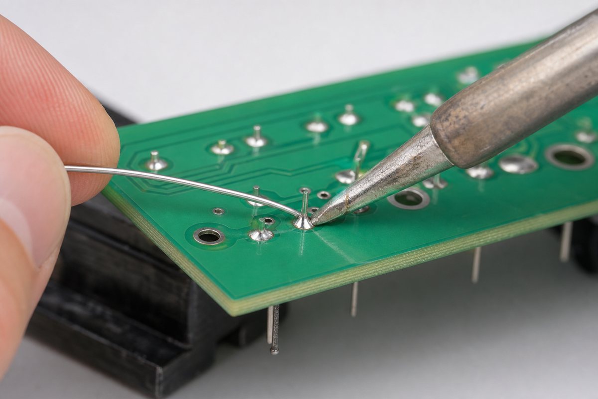
After the joint cools, the solder should remain around the lead and within the copper pad. If it does not form after a short heating period, stop instead of repeatedly reheating the area. First clean the surfaces and inspect the tip, then decide whether more flux or a larger tip is needed.
How to Clean PCB Board After Soldering?
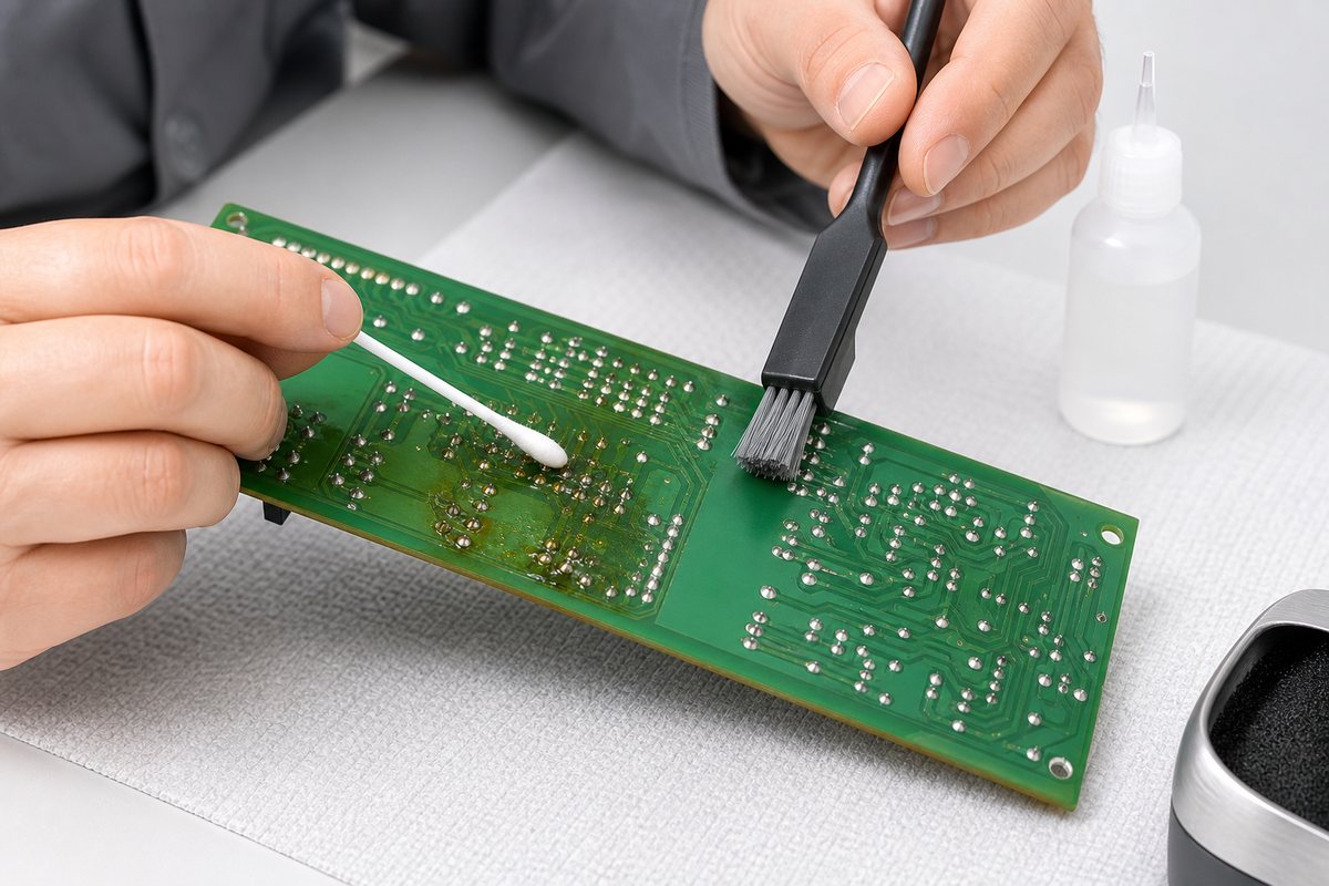
Clean a PCB after soldering when the flux chemistry or product requirements call for it. Disconnect power and let the board cool before choosing a cleaner, because different flux residues require different removal methods.
Once the correct cleaner has been selected, use the following sequence to remove residue without spreading it across the board:
- Apply an approved electronics cleaner or high-purity isopropyl alcohol.
- Agitate the residue with a lint-free swab or ESD-safe brush.
- Lift or rinse away the dissolved material instead of spreading it.
- Avoid forcing liquid beneath switches, microphones, and unsealed parts.
- Dry the assembly completely and inspect it under magnification.
The final inspection matters because simple wiping can dissolve flux and move it to another area. Activated and water-soluble residues usually need thorough removal, while permitted no-clean residue may remain on the board. Cleaning can still be necessary before conformal coating.
How Can You Recognize and Fix Poor Solder Joints?
Poor solder joints often show incomplete wetting or the wrong amount of solder. Cracks, bridges, and heat damage are also warning signs, and magnification makes them easier to see before electrical testing.
Each defect needs a different correction. Use the joint’s visible condition to choose the next step:
- Cold or disturbed joint: remove contamination, add flux, and reheat both metals evenly.
- Solder bridge: remove excess alloy with solder wick or controlled desoldering equipment.
- Insufficient solder: reheat the joint and add only enough solder to complete the fillet.
- Excess solder: remove enough material to reveal the joint shape and prevent hidden shorts.
- Lifted pad or damaged barrel: stop heating and evaluate whether an approved conductor repair is possible.
After the repair, inspect the joint again before returning power to the board. Check that the intended connection has continuity and that neighboring conductors remain isolated. Lead-free joints can look duller than tin-lead joints, so shine alone does not prove quality.
Is It Okay to Put a Soldering Iron on a PCB Board?
Yes, the soldering tip may briefly touch the intended copper pad and component lead, but it should not rest elsewhere on the PCB. Keep it away from the solder mask and unrelated traces, and never use pressure to force heat into the joint.
Long contact can soften the adhesive beneath a copper pad and eventually lift it from the board. The surrounding mask or laminate may also darken and blister. Stop immediately when any of these signs appear.
A clean tip with the correct shape usually completes the joint faster than a tiny oxidized tip. Good thermal contact protects the PCB because the required energy enters the connection quickly, reducing total heating time.
When Is Manual Soldering No Longer Suitable?
Manual soldering is no longer suitable when joints are too small to reach reliably or are hidden beneath a component. It also becomes inefficient when the same connections appear across many boards. Fine-pitch SMT parts and BGA packages therefore usually require stencil printing, accurate placement, and controlled reflow.
Wave or selective soldering becomes more practical when a board contains many through-hole joints. These systems repeat the same heating and solder delivery conditions more consistently than hand work.
Manual soldering remains valuable for prototypes, wire connections, selected connectors, and controlled rework. Move to a machine process when many boards must receive the same thermal conditions and produce consistent inspection results.
FAQ About PCB Board Soldering
Why does solder form a ball instead of sticking to the PCB?
The pad may be oxidized, contaminated, or too cold. Clean the surface, use compatible flux, and heat the pad and lead together with a clean, tinned tip.
Should every solder joint look shiny?
No. Lead-free joints often look duller than tin-lead joints. Judge wetting, shape, cracks, bridges, and stability instead of using shine as the only acceptance criterion.
Can you solder wires directly to a PCB?
Yes, when the board has a suitable pad or plated hole and the wire receives strain relief. Avoid excessive solder wicking because it can make the wire rigid near the joint.
Do no-clean flux residues need to be removed?
Not always. Removal may still be necessary for appearance, high-impedance circuits, electrical testing, conformal coating, or environmental requirements defined by the product.
How long should a soldering iron touch a PCB pad?
Only long enough to produce full wetting, usually a few seconds during normal hand soldering. If the joint needs prolonged contact, stop and correct the heat-transfer problem.
Can you mix lead-free and tin-lead solder?
Mixing is sometimes possible during controlled repair, but it changes the alloy composition and melting behavior. Follow the assembly specification and avoid uncontrolled mixing.
Can a soldered PCB be tested immediately?
Inspect and clean the board first, then confirm that the joint has cooled and any cleaning liquid has fully evaporated. Check for bridges before applying power.
When should you stop repairing a solder joint?
Stop when the pad lifts, the plated hole loosens, the laminate chars, or repeated heating no longer restores a stable connection. Further work may cause permanent PCB damage.
How Can EBest Circuit Support PCB Assembly?
Reliable soldering begins with compatible component footprints and a suitable board finish. Clear assembly data then allows the production process to be set up correctly. EBest Circuit supports PCB fabrication and assembly from prototypes through production, with SMT, through-hole assembly, inspection, and engineering review available for suitable projects.
Send your Gerber files and BOM to sales@bestpcbs.com, together with the required quantity and any special soldering instructions. Placement data and assembly drawings will help our team review the package and discuss a practical manufacturing route.