Sourcing an optical transceiver PCB assembly supplier takes more than checking whether a factory offers SMT. Compact layouts, fine-pitch packages, controlled-impedance routing, critical ICs, and tight test requirements can affect assembly yield, inspection coverage, lead time, and final cost.
This guide follows the decisions buyers and engineers usually need to make before placing an order: supplier capability, assembly risks, inspection, board-level testing, prototype release, RFQ preparation, and quote comparison.

What Does Optical Transceiver PCB Assembly Include?
The first step is to define exactly what the supplier is quoting. Optical transceiver PCB assembly usually covers the PCB, components, assembly, inspection, and agreed board-level testing, but it does not automatically include full optical module validation.
- PCB fabrication: material, stackup, controlled impedance, vias, surface finish, dimensions, and electrical testing.
- Component sourcing: approved MPNs, consigned parts, approved alternates, storage, and traceability requirements.
- PCB assembly: solder-paste printing, placement, reflow, secondary assembly, inspection, cleaning, and controlled rework.
- Board-level testing: power-up, rail measurements, current consumption, programming, communications, and fixture-based electrical checks.
Optical alignment, transmitter power, receiver sensitivity, wavelength testing, BER testing, calibration, and full module validation should be quoted separately unless they are explicitly included.
What Should You Check Before Choosing an Optical Transceiver PCB Assembly Supplier?
Supplier evaluation should be based on the actual PCB design, package mix, sourcing model, and test requirements. A general statement such as “we support SMT assembly” does not show whether the factory can handle a dense optical transceiver board.
- Fine-pitch capability: smallest passive size and BGA pitch.
- BGA/QFN/LGA assembly: process and inspection capability for bottom-terminated packages.
- PCB fabrication: controlled impedance, stackup, via structure, material, thickness, and finish.
- Component sourcing: exact MPNs, consigned parts, approved alternates, and no-substitution devices.
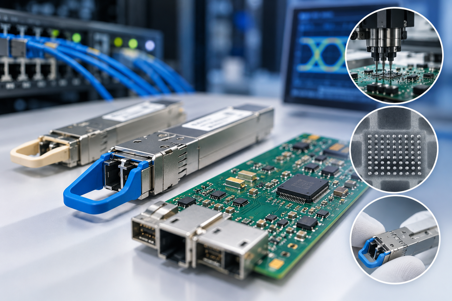
- Inspection: SPI, AOI, X-ray, microscopic inspection, and first-article inspection where required.
- Testing: power checks, programming, communications, and fixture-based electrical testing.
- Production support: ability to carry the same files, inspection criteria, and test limits from prototype into repeat production.
Review PCB fabrication and assembly together. Stackup or impedance problems cannot be corrected during SMT, while package, speed grade, temperature range, and revision requirements for critical ICs should be controlled directly through the BOM.
Where Can Optical Transceiver PCB Assembly Quality Go Wrong?
The highest-risk defects are often those that survive basic visual inspection and appear only during electrical testing or module integration. Linking each risk to a specific inspection or control method makes supplier requirements easier to define.
| Risk Area | Possible Issue | What to Verify |
|---|---|---|
| BGA/QFN/LGA joints | Opens, bridges, misalignment, voiding | X-ray coverage |
| Fine-pitch parts | Shift, bridging, insufficient solder | SPI, AOI, first article |
| Critical ICs | Wrong MPN, package, speed grade, revision | BOM and substitution rules |
| Power circuits | Abnormal current draw, unstable startup, resets | Rail and current testing |
| High-speed interfaces | Intermittent communication | Impedance control and assembly quality |
| Thermal areas | Poor heat transfer | Thermal component placement and solder quality |
For hidden joints, specify which packages require X-ray and whether inspection is 100% or sample-based. For critical ICs, use no substitution or an approved-alternates list rather than leaving replacements open.
Which Inspection Methods Are Needed for Optical Transceiver PCB Assembly?
Inspection should follow the package type and likely defect, because no single method covers paste deposition, visible solder joints, and hidden terminations at the same time.
| Inspection Method | What It Checks | Best Use |
|---|---|---|
| SPI | Paste volume, height, area, alignment | Fine-pitch SMT |
| AOI | Missing parts, polarity, placement, visible solder | General SMT inspection |
| X-ray | Hidden joints, bridges, alignment, voiding | BGA, QFN, LGA |
| Microscopic inspection | Rework areas, connectors, contamination | Detailed visual checks |
AOI cannot fully inspect joints beneath BGA, QFN, or LGA packages. For boards using these packages, define X-ray locations, coverage, sampling, and reporting requirements before production.

Where Does PCB Assembly Testing End and Optical Module Validation Begin?
Testing scope should separate board-level electrical checks from tests that depend on the complete optical path. This avoids treating PCBA testing and finished-module validation as the same service.
| PCB-Level Testing | Module-Level Validation |
|---|---|
| Short-circuit check | Optical output power |
| Power-up | Wavelength |
| Rail-voltage measurement | Receiver sensitivity |
| Current measurement | BER testing |
| Programming | Optical alignment |
| Communication check | Module thermal performance |
| Fixture-based electrical test | Interoperability |
If the assembler is responsible for board-level functional testing, provide the fixture, firmware version, software, cables, test sequence, and pass/fail limits. BER, receiver sensitivity, optical power, and alignment should remain separate unless the supplier is specifically responsible for finished-module validation.
Which Quality and Traceability Records Should Buyers Request?
Traceability requirements should be agreed before RFQ release so suppliers price the same documentation scope. The deepest records should follow the components and processes with the greatest impact on failure analysis.
For critical ICs, records may include:
- manufacturer part number;
- lot or date code where required;
- sourcing information;
- incoming inspection record;
- approved substitution or deviation.
Build records may include:
- PCB and BOM revision;
- firmware revision;
- production date;
- lot or work-order number;
- quantity;
- inspection status;
- test status.
For higher-risk builds, first-article results, X-ray records, test data, rework history, and engineering-change records can also be retained. A DSP, FPGA, MCU, TIA, or laser driver generally needs deeper traceability than a standard passive component.
What Should You Include in an Optical Transceiver PCB Assembly RFQ?
A complete RFQ should give the supplier enough information to price the PCB, components, assembly, inspection, testing, and delivery without relying on assumptions. Missing information at this stage often appears later as quote revisions, material costs, or test charges.
For PCB fabrication, provide:
- Gerber or ODB++
- drill files;
- PCB drawing;
- stackup;
- material;
- controlled-impedance requirements;
- surface finish;
- special dimensional requirements.
For assembly, provide:
- BOM with exact MPNs
- reference designators;
- DNP information;
- approved alternates;
- pick-and-place file;
- assembly drawing;
- polarity and special assembly notes.
For quotation and delivery, provide:
- prototype quantity
- expected production quantity;
- required delivery date;
- shipping destination;
- turnkey or consigned-material requirements;
- customer-supplied parts;
- substitution restrictions;
- MOQ requirements.
For inspection and testing, provide:
- packages requiring X-ray;
- inspection coverage or sampling;
- required reports;
- programming files;
- firmware version;
- fixture information;
- test procedure;
- pass/fail limits;
- required test data.
State clearly whether the RFQ covers assembled PCBs only or also includes optical subassemblies, enclosure work, calibration, BER testing, or full module validation.
How Should You Compare Optical Transceiver PCB Assembly Quotes?
Quote comparison should start only after the manufacturing and testing scope has been normalized. Otherwise, a lower unit price may simply exclude work that another supplier has already included.
| Quote Item | What to Compare |
|---|---|
| Components | MPNs, approved sources, alternates, attrition |
| PCB fabrication | Material, stackup, impedance, finish |
| Tooling/NRE | Stencil, programming setup, fixture, test development |
| Inspection | AOI/X-ray coverage, first article, sampling, reports |
| Testing | Power-up, programming, fixture-based test, module validation |
| MOQ/excess material | Minimum buys and ownership of unused parts |
| Lead time | Whether component procurement is included |
| Traceability | Records supplied or retained |
Compare the complete quoted scope, not just the unit price. X-ray, programming, fixture development, excess material, or test time can materially change the final project cost.
When Is an Optical Transceiver PCBA Prototype Ready for Production?
After the prototype passes, the next decision is whether the result can be repeated without manual fixes or undocumented engineering changes. Production release should be based on repeatability rather than a single working sample.
Before increasing quantity, confirm that:
- PCB data, BOM, pick-and-place files, drawings, firmware, and test requirements use the same revision.
- Prototype failures have been traced to their root causes.
- The build no longer depends on repeated manual rework.
- Critical parts are available for the planned quantity.
- Approved alternates are documented.
- MOQ and excess-material costs are understood.
- Inspection can be repeated in production.
- Test limits are fixed.
- Packaging, labeling, and lot identification are defined.
A prototype that works only after manual correction is not production-ready. Any stencil, BOM, programming, inspection, or test change made during prototyping should be included in the released production package.
Why Choose EBest Circuit for Optical Transceiver PCB Assembly?
For optical transceiver projects, the practical benefit of a PCBA supplier comes from reducing handoffs, handling dense assemblies, controlling critical materials, and supporting the move from prototype to repeat production.
- PCB and PCBA from one supplier: PCB fabrication, component sourcing, and assembly can be managed within one manufacturing workflow, reducing coordination between separate vendors.
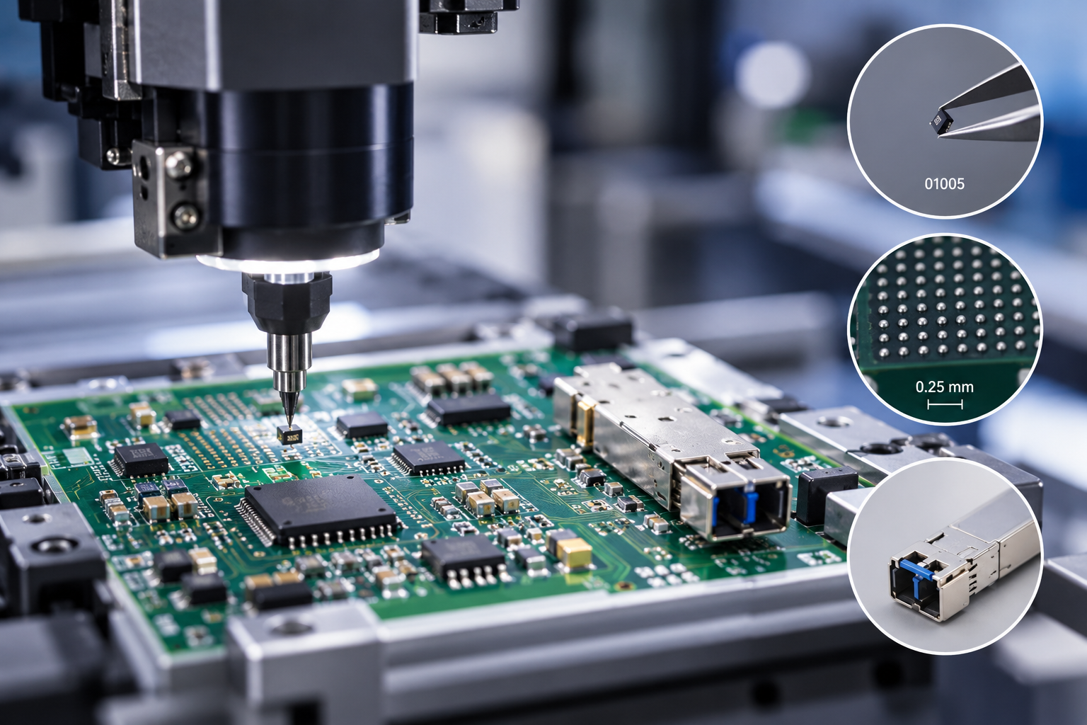
- Fine-pitch assembly capability: EBest Circuit supports 01005 components and BGA pitches down to 0.25 mm, suitable for compact boards with dense component placement.
- Flexible component sourcing: Turnkey and customer-supplied parts can be combined, with support for reels, cut tape, tubes, trays, and loose parts.
- Prototype before volume production: Prototype and quick-turn assembly help identify BOM, soldering, inspection, and test issues before larger material commitments are made.
- SMT, THT, and mixed assembly: Surface-mount devices, through-hole connectors, and mixed assemblies can remain within the same project.
- Controlled production: EBest Circuit operates under ISO 9001, ISO 13485, IATF 16949, and AS9100D, supporting documented process control and traceability.
- RFQ review before production: PCB files, BOMs, sourcing requirements, inspection scope, and test requirements can be reviewed before quotation, reducing avoidable revisions after the PO is placed.
FAQs About Optical Transceiver PCB Assembly
Q1: Can customer-supplied DSPs, TIAs, or laser drivers be used?
A1: Yes. Consigned critical ICs can be combined with supplier-sourced components. Mark each consigned item clearly in the BOM.
Q2: How much component overage should be supplied for prototype assembly?
A2: The amount depends on package size, build quantity, packaging format, and component value. Small passives generally require more attrition allowance than expensive devices supplied in trays or tubes.
Q3: Can prototype and production orders use different sourcing models?
A3: Yes. Prototype builds may use customer-supplied parts and later move to turnkey sourcing. Update the BOM and purchasing instructions when responsibility changes.
Q4: How are moisture-sensitive components handled before assembly?
A4: Moisture-sensitive devices should remain in suitable packaging and follow the required storage, floor-life, baking, and reflow controls for their MSL classification.
Q5: Can serialized labels be added to each PCBA?
A5: Yes. Provide the label format, location, barcode or serial-number structure, and data requirements before production.
Q6: Can finished PCBAs be packed in ESD trays instead of bags?
A6: Yes. Packaging can be specified around board size, connector protection, ESD requirements, and downstream handling.
Q7: What happens to unused customer-supplied components?
A7: They can be returned, stored for repeat orders, or handled according to the customer’s material instructions.
Q8: Can programming be completed before shipment?
A8: Yes. Provide the programming file, target device, programming method, and verification requirements.
Q9: Can the first assembled boards be reviewed before the full lot continues?
A9: Yes. A first-article hold point can be added when customer approval is required before the remaining quantity proceeds.
Q10: Can assembly photos or X-ray images be supplied with the order?
A10: Yes. Specify the required package locations, image format, sampling, and reporting scope before quotation.
Request an Optical Transceiver PCB Assembly Quote
For an accurate quote, send the files and requirements used to define the build: PCB data, BOM, pick-and-place file, quantity, target delivery date, sourcing model, inspection scope, and test requirements. Send the package to EBest Circuit via sales@bestpcbs.com for review before quotation.