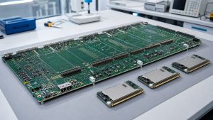
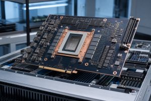
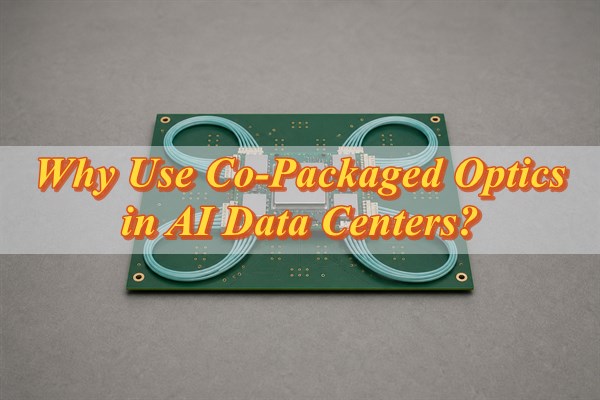
Co-packaged optics places optical engines beside a processor or switch chip within a common package assembly. Moving electrical-to-optical conversion closer to the silicon shortens the high-speed connection that would otherwise cross a board to a front-panel transceiver. For AI data centers, this can provide more bandwidth within interconnect power and space limits. The exchange is tighter integration: package design, cooling, fiber handling, and service procedures become more demanding. A useful platform comparison weighs those costs against the electrical bottleneck CPO can remove.
What Is Co-Packaged Optics (CPO)?
Co-packaged optics is an integration approach, not a network protocol or a particular optical speed. A switch application-specific integrated circuit (ASIC) still processes traffic electronically. Nearby optical engines convert outgoing data into optical signals and convert received light back into electrical signals.
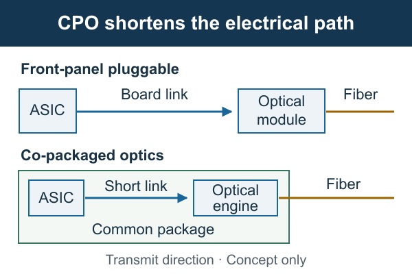
In a conventional pluggable design, the ASIC connects electrically to a transceiver at the chassis faceplate. In CPO, the optical engine shares a package-level assembly with the ASIC; fiber carries the optical signal toward the faceplate and onward. The engines do not have to be fabricated on the same silicon die as the processor.
This distinction matters when reading product descriptions. A device can use silicon photonics inside a front-panel module without being co-packaged. Conversely, a CPO label alone does not specify the laser location, optical reach, cooling method, or replaceable unit. Those details belong to the implementation.
Why Is Co-Packaged Optics Important for AI Data Centers?
CPO addresses the electrical distance and power needed to move data between high-bandwidth chips and optical links. Distributed training exchanges gradients and other data across accelerators; some inference deployments also move substantial traffic between compute nodes. When communication delays useful computation, adding more GPUs does not necessarily produce a proportional gain.
As electrical signaling rates rise, package transitions, board traces, vias, and connectors consume channel margin. Equalization and retiming can recover degraded signals, but they require power and introduce design constraints. Moving conversion closer to the ASIC reduces the electrical path that must sustain the highest rates.
- Interconnect power: A shorter electrical channel can reduce signal-conditioning requirements. Compare complete link power at equal delivered bandwidth, including host I/O, optical engines, lasers, and any cooling overhead; module watts alone are not a system comparison.
- Bandwidth density: Optical engines near the chip can reduce dependence on long electrical escapes to front-panel modules. The resulting design must still accommodate fiber exits, connectors, cooling hardware, and assembly access.
- Useful compute time: A stable, adequately provisioned fabric helps keep accelerators supplied with data. Confirm the benefit with representative communication patterns and job-completion measurements, since CPO cannot fix oversubscription, congestion policy, or an inefficient training strategy.
The strongest case is a system whose electrical I/O power, channel margin, or packaging density is already limiting its next bandwidth step. A smaller installation with adequate links and strict field-replacement requirements may have little reason to change architectures.
How Does Co-Packaged Optics Work?
The signal changes from electrical to optical close to the ASIC, then follows an optical link to its destination. The shortened segment is the local chip-to-engine connection; CPO does not turn the processor or every connection on the board into an optical device.
- Generate the electrical signal. The ASIC’s serializer/deserializer (SerDes) sends high-speed electrical data over a package-level connection to the optical engine. Channel validation checks whether that interface meets the selected electrical specification.
- Modulate the light. Driver electronics control an optical modulator using light supplied by the laser arrangement. The resulting optical waveform carries the data; the laser may be external to the hot package.
- Couple into fiber. Optical couplers and fiber attachments transfer light from the engine into the fiber path. Coupling loss, connector loss, and fiber loss consume the link’s optical budget.
- Recover the received data. A photodetector converts incoming light into current, and receiver electronics recover an electrical signal for the destination. End-to-end error measurements verify the link, including the agreed error-correction conditions.
What Are the Main Components of a CPO System?
A working CPO system needs an electrical processor, optical conversion, a light source, and mechanical and thermal support. A block diagram should identify who supplies and validates each interface, not merely name the chips.
- Switch ASIC or compute device: Generates and receives data through compatible electrical I/O. Its lane configuration and management requirements constrain the engine arrangement.
- Optical engine: Combines photonic functions with driver and receiver electronics. Check both electrical and optical interfaces; an advertised aggregate bandwidth does not establish compatibility.
- Laser source: Supplies optical power. An external laser can separate laser servicing and some thermal concerns from the main package, but adds delivery fibers, connections, and its own fault-management requirements.
- Package substrate and interconnect: Connect the ASIC and engines while supporting power distribution and mechanical attachment. Electrical, thermal, and assembly constraints must be reviewed together.
- Fiber attachment and connectors: Route light between the engines and the external network. Alignment, bend limits, contamination control, and access determine whether the link remains usable after assembly and servicing.
- Host board, cooling, and control: Provide power, monitoring, mechanical support, and heat removal. These remain necessary even when selected high-speed traces no longer traverse the host PCB.
How Do CPO, NPO, and LPO Compare with Pluggable Optics?
Compare physical integration first, then compare signal processing. Front-panel pluggable optics, near-package optics (NPO), and CPO describe where conversion sits. Linear pluggable optics (LPO) is a type of pluggable optical implementation, not a fourth mutually exclusive location.
| Integration | Conversion location | Design consequence |
|---|---|---|
| Front-panel pluggable | Removable module at the faceplate | The host electrical channel reaches the module; module replacement is accessible. |
| Near-package optics | Close to, but outside, the ASIC’s package | A shorter board-level path is possible; mounting and service access depend on the design. |
| Co-packaged optics | Optical engines in a common package assembly with the ASIC | The critical electrical connection moves into the package; optical and cooling integration become central. |
Within the pluggable category, a conventional retimed module includes digital signal processing, while LPO removes the module DSP and relies on suitable host SerDes capabilities across the link. The LPO MSA’s interface explanation makes that distinction explicit. LPO therefore preserves a pluggable form factor while changing host-channel and interoperability requirements.
A useful evaluation asks two separate questions: where should conversion occur, and where should equalization or retiming occur? CPO is not automatically the lowest-power or lowest-cost answer, and LPO is not a drop-in upgrade for every existing port. Compare validated configurations at the same reach, bandwidth, error performance, and maintenance requirements.
How Is CPO Used in Scale-Up and Scale-Out AI Networks?
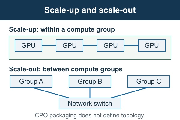
CPO can support either network domain, but scale-up and scale-out describe communication roles rather than packaging choices. The correct starting point is the required topology, protocol, distance, and latency—not the assumption that every AI link needs optics.
Scale-up connects accelerators into a tightly coupled compute system. Such links can have demanding latency, bandwidth, and memory-access requirements. Copper remains useful for suitable short connections; optical I/O becomes relevant when the required reach or system size exceeds the practical electrical design.
Scale-out connects servers or compute groups through a wider network fabric. A CPO switch can place conversion near its switching ASIC while a server endpoint still uses a compatible pluggable transceiver. The endpoints need matching optical interfaces and protocol behavior, not matching packaging labels.
Before a comparison, list the traffic that crosses each boundary: accelerator-to-accelerator exchanges, server-to-server collectives, and traffic between larger clusters. Then identify where electrical reach or power becomes restrictive. This avoids spending a packaging premium on links that are not the bottleneck.
What Does CPO Change for PCB and Package Design?
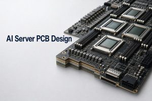
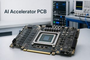
CPO moves selected high-speed design problems into the package; it does not remove the need for a carefully engineered PCB. The package team owns the chip-to-engine connection. The board team still has to deliver power, route remaining interfaces, support the assembly, and provide usable access for cooling and fiber handling.
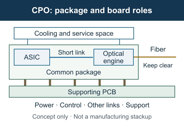
Package and board channels. A chip-to-engine connection confined to the package should not be assigned a host-PCB trace budget. Remaining high-speed board interfaces still require loss, reflection, crosstalk, and return-path analysis. Build a channel map showing every transmitter, receiver, transition, and connector before selecting materials.
This is why “CPO allows a cheaper PCB” is an incomplete conclusion. Fewer long optical-module routes may ease one constraint, while dense package escape, power delivery, other high-speed links, and assembly requirements continue to influence the stackup. Select laminate and via construction from the remaining channel budgets and fabrication tolerances, not from the CPO label.
Power delivery. ASIC load changes can create rail droop or noise if the board-package power-delivery network (PDN) has excessive impedance. Optical electronics may have separate supply-noise limits. Obtain rail specifications, transient-load information, package models, and decoupling constraints; then evaluate the combined PDN rather than checking the board in isolation.
The useful output is a set of verified rail margins over the relevant operating conditions. Where measurements disagree with simulation, investigate the model boundary, probe setup, and current transient before adding capacitors indiscriminately. Coordinate these checks with the stackup and channel budgets used in AI server PCB design.
Cooling, warpage, and fiber access. Optical engines near a hot ASIC must remain within their specified thermal conditions. Heat-sink or cold-plate hardware needs clearance, mounting loads, and service access. Review the full temperature distribution and tolerance stack; a passing ASIC junction temperature alone does not validate neighboring optics.
Package and board deformation can affect attachment reliability and alignment-sensitive interfaces. Mechanical analysis should use the actual materials, assembly sequence, and mounting conditions. Fiber exits need protected routes with supplier-specified bend limits and strain relief, including the space a technician needs to remove adjacent hardware.
| Design area | CPO-related change | Required handoff |
|---|---|---|
| High-speed channel | Selected paths move from host board to package. | Separate package and PCB channel budgets, models, and compliance results. |
| Power delivery | ASIC and optical supplies share a constrained assembly. | Rail limits, transient models, decoupling allocation, and measured margins. |
| Mechanical integration | Cooling hardware and fiber routes compete for access. | Tolerance analysis, keep-outs, mounting loads, and service clearances. |
| Assembly and test | An electrical board test cannot validate the complete optical path. | Process sequence, optical test access, acceptance limits, and failure ownership. |
Assembly and test. Agree on incoming package checks, board assembly inspection, electrical bring-up, and end-to-end optical tests before releasing fabrication data. Confirm which parts tolerate each assembly or cleaning step and when fibers are attached. Do not assume that a normal board rework process is acceptable for an integrated optical assembly.
Consider a hypothetical link that fails only after the cooling assembly is installed. Compare optical loss, rail behavior, temperature, and connector seating before assigning the fault to PCB impedance. A repeatable change in coupling loss with mechanical loading points toward the attachment or fiber path; rail disturbance under load calls for power-delivery checks. Use the observations to choose the next test instead of changing board materials first.
What Are the Main Challenges of Co-Packaged Optics?
The main challenges are achieving acceptable integrated yield, thermal behavior, test coverage, and repairability. Shortening an electrical link removes some difficulties while combining components that previously could be tested or replaced separately.
- Yield and failure isolation: An integrated assembly can contain valuable known-good components before a later fault is found. Establish pre-assembly screening, test access, and allowed rework stages so one failed element does not automatically consume the entire assembly.
- Temperature-dependent optical behavior: Heating can change device behavior and alignment conditions. Validate the link across specified temperatures and realistic neighboring ASIC loads, including any tuning or control overhead.
- Fiber handling and cleanliness: Tight routing, strained attachments, or contaminated interfaces can reduce optical margin. Check loss after final mechanical assembly and after the intended maintenance procedure, not only on an open bench.
- Serviceability: A replaceable external laser does not make an optical engine or ASIC package field-replaceable. Identify the actual failed-unit replacement procedure, the affected ports, spare requirements, and recovery time.
- Interoperability and supply continuity: Standards alignment does not prove that arbitrary engines, hosts, and firmware work together. Require a qualified configuration and a controlled substitution process for components that affect the link.
These risks belong in a system qualification plan. Neither a low engine-power figure nor a successful demonstration answers how the platform behaves under faults, maintenance, and sustained workload.
How Mature Is CPO for Commercial Deployment?
CPO has moved beyond laboratory-only demonstrations, but procurement readiness remains product-specific. Distinguish a technology demonstration, early-access shipment, volume-production announcement, and a supported system that your organization can order and qualify.
Broadcom’s October 2025 Tomahawk 6–Davisson announcement describes a 102.4-Tb/s CPO switch and says shipments have begun. Its availability section also describes sampling to early-access customers. Before ordering, confirm whether your chosen system is in sampling, qualification, or general availability.
In its June 1, 2026 COMPUTEX update, NVIDIA states that Spectrum-X Ethernet Photonics is in full production. This is a vendor production statement, not an independent measurement of installed market share or proof that every customer’s delivery, qualification, and service requirements are satisfied.
For a purchase decision, ask the system supplier for the exact orderable configuration, qualification coverage, committed lead time, supported optics at the far end, and field-service procedure. A roadmap is useful for planning; those records are needed for deployment.
Is Co-Packaged Optics Right for Your AI Data Center?
CPO is a good fit when it delivers measurable workload gains and your team can support its integration and maintenance requirements. Compare complete network configurations at the same port rate, reach, cooling conditions, and error-correction settings. Use the following checks to test the case for deployment.
- Locate the bottleneck. Measure traffic demand, congestion, accelerator waiting time, and link utilization. The result should show whether network capacity, electrical I/O, or another resource constrains the job.
- Normalize performance and power. Compare equal usable bandwidth and reach at representative load. Record which I/O, laser, control, and cooling contributions are included.
- Qualify the complete link. Test the proposed host, firmware, engine, fiber, connectors, and remote endpoint together. Retain error-rate, optical-margin, and restart results under agreed conditions.
- Exercise maintenance and faults. Demonstrate isolation and replacement for the likely failure units. Record ports affected, recovery behavior, and the time needed to return to service.
- Review manufacturing and lifecycle support. Confirm production test coverage, acceptable substitutions, spares, and repair terms. Use those inputs with acquisition and operating costs to compare lifecycle expense.
A pilot should have explicit acceptance thresholds and a fallback. If the expected gain appears only in a component specification and not in the workload or operating plan, the deployment case is not yet established.
FAQs About Co-Packaged Optics
Q1. Is silicon photonics the same as co-packaged optics?
A1. No. Silicon photonics describes an implementation technology for optical functions. CPO describes their integration near an electronic chip within a package assembly. Silicon-photonics devices can also be used inside pluggable modules, so the technology name alone does not identify the packaging architecture.
Q2. Will CPO replace all pluggable transceivers?
A2. No universal replacement follows from CPO adoption. Pluggables can remain appropriate where modular replacement, varied reaches, and existing platform compatibility matter. A CPO switch can also connect to a compatible pluggable endpoint. The decision is made for a specific link and service model.
Q3. Does CPO eliminate DSPs and retimers?
A3. Not by definition. A shorter channel can change the amount and location of signal conditioning, but the CPO label does not specify every electronic function. Check the actual host and engine architecture before assuming a DSP-free path or assigning a latency saving.
Q4. Is CPO only for Ethernet switches?
A4. No. Optical integration can be applied to other switching and compute devices. Protocol support, electrical interfaces, and software integration still need to be demonstrated for the intended platform. A working Ethernet switch implementation is not proof of compatibility with an accelerator’s scale-up interface.
Q5. Does every CPO design require an external laser?
A5. No. Laser placement is an implementation choice. An external source can offer thermal separation and a replaceable laser unit, while adding optical delivery and management requirements. Confirm the specified laser arrangement and which failure units are actually replaceable.
Q6. Is there a fixed maximum reach for CPO?
A6. No. Reach depends on the optical interface, wavelength arrangement, fiber, connector losses, receiver performance, and link budget. CPO identifies where conversion takes place. Use the selected interface specification and the complete installed path to establish reach and margin.
Q7. Can CPO connect directly to an LPO endpoint?
A7. Some implementations support that configuration, but the labels alone do not guarantee it. Require a supplier-qualified combination of host, module, optical interface, firmware, and error-correction settings. Equal nominal port speeds are insufficient evidence of interoperability.
Q8. Does CPO require liquid cooling?
A8. CPO does not define a cooling method. Cooling depends on ASIC power, engine limits, package geometry, airflow or coolant conditions, and system density. Follow the specific platform’s thermal requirements and validate optical performance after the complete cooling assembly is installed.
Q9. Can a standard PCB supplier manufacture the optical package?
A9. PCB fabrication, board assembly, semiconductor packaging, and photonic integration are different processes. Qualify suppliers for the actual work and interfaces they own. Experience with a supporting PCB does not by itself establish capability for optical-engine fabrication or precision fiber attachment.
Conclusion
CPO is valuable when moving optical conversion closer to the chip solves a demonstrated interconnect constraint. Its benefits must survive the rest of the design: package yield, board power delivery, thermal integration, optical testing, and field maintenance.
For supporting PCB or PCBA work, email sales@bestpcbs.com with your fabrication files, proposed stackup, BOM with exact part numbers or acceptable alternatives, quantity, target delivery date, and traceability requirements. Include assembly drawings, package-interface limits, and fiber or cooling keep-outs. BestPCBS can use these inputs for a free DFM review of the supporting board and a project-specific quotation, identifying fabrication or assembly questions before the design is released. Optical-engine and semiconductor-package qualification remains with the suppliers responsible for those processes.