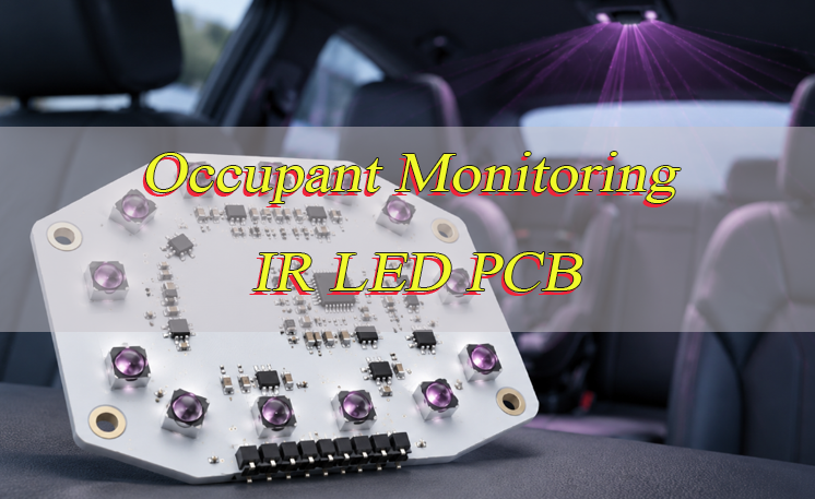
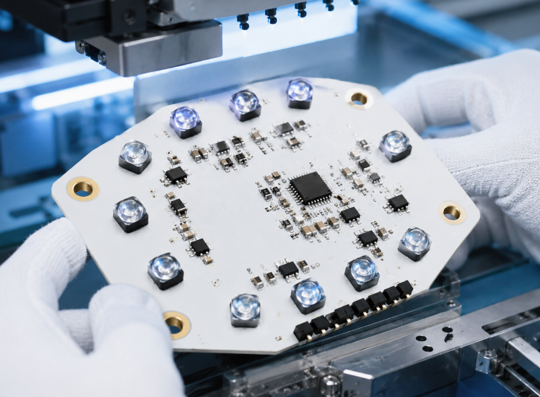
An occupant monitoring IR LED PCB provides near-infrared illumination for camera-based Occupant Monitoring Systems across front-passenger, rear-seat, and child-restraint areas. The PCB has to match the camera FOV, seating geometry, IR wavelength, LED beam pattern, drive conditions, thermal path, and housing position so the camera receives usable illumination across the cabin instead of a bright center with weak outer or rear-seat coverage.
Are you facing these challenges in an automotive OMS illumination project?
- Rear-seat or edge-of-FOV areas are noticeably darker than the center of the cabin, even though the total IR output appears sufficient.
- LED output changes with drive current, temperature, or installation angle, making illumination difficult to keep consistent across several seating positions.
- The prototype performs correctly, but LED alignment or assembly variation changes when production quantity increases.
EBest Circuit supports PCB design, prototyping, component sourcing, PCB assembly, and mass production. For an occupant monitoring IR LED PCB, the approved PCB construction, LED footprint, assembly data, and controlled component list can remain consistent as the project moves from engineering samples into repeat builds.
- Improve multi-seat illumination uniformity: Match camera FOV, rear-seat distance, child-restraint areas, LED beam angle, emitter position, and beam overlap before the PCB geometry is frozen. This avoids solving a weak rear-seat image by simply making the center brighter.
- Keep LED output stable under electrical and thermal load: Size LED current paths, driver placement, copper area, thermal vias, and heat-transfer structure around the selected emitter and drive conditions so voltage drop or temperature differences do not create uneven output.
- Keep production units aligned with the approved prototype: Control LED footprint, placement, PCB dimensions, board flatness, critical BOM parts, and assembly orientation so optical geometry remains repeatable when production quantity increases.
For an occupant monitoring IR LED PCB project, send your PCB files, IR LED part number, camera FOV, cabin coverage requirements, drive conditions, board dimensions, thermal requirements, and expected quantity to sales@bestpcbs.com.
What Does an Occupant Monitoring IR LED PCB Do in Automotive OMS?
An occupant monitoring IR LED PCB provides controlled infrared illumination to the seating areas monitored by the OMS camera. The board must cover the required cabin zones while keeping LED current, temperature, and optical alignment within the approved design range.
- Front-passenger area: Illuminate the face and upper body without directing most of the available IR energy toward the nearest seat.
- Rear seating positions: Provide sufficient illumination to left, center, and right rear-seat regions despite longer optical distance and larger off-axis angles.
- Child-restraint areas: Extend coverage lower into the rear-seat region because a child may sit below the adult head position used during normal occupant monitoring.
- Edge-of-FOV areas: Keep image regions near the sides of a wide camera view from becoming substantially darker than the center.
A board may pass its electrical checks and still produce a poor OMS image if the emitters illuminate the wrong cabin regions. Optical coverage therefore has to be validated separately from basic LED function.
Why Is Rear-Seat Coverage Harder Than Front-Seat Illumination?
Rear-seat illumination has to cover longer optical distances, wider seating areas, and more possible obstructions than front-seat illumination.
- Longer optical distance: Rear occupants receive less irradiance than closer targets under the same emitter conditions. Rear-seat performance should be checked independently rather than inferred from the front-row image.
- Wider horizontal area: A rear bench may contain three seating positions spread across a much larger angle than one front-seat target.
- Different vertical positions: Adults, children, and child-restraint systems occupy different regions in the camera image. Illumination aimed mainly at adult head height can leave lower areas weak.
- Seat obstruction: Front-seat headrests, seatbacks, occupants, and child-seat structures can block part of the direct IR path.
- Off-axis loss: Radiant intensity normally falls toward the outer part of an LED beam, so side seats can receive less illumination even when the center seat is well exposed.
If a rear-seat region is too dark, review emitter position, beam direction, and beam overlap before increasing current through the entire array. Higher current may brighten the center without correcting the coverage problem.
How Should IR Wavelength and Beam Angle Be Selected for Multi-Seat OMS?
Select the emitter by matching camera sensitivity, optical filtering, cabin coverage, and installed geometry. For an occupant monitoring IR LED PCB, 940 nm is commonly used when low visible glow is preferred, but the final wavelength still has to suit the camera sensor and optical filter.
- Wavelength: Compare the camera response with optical-filter transmission. Lower visible glow is useful only when enough IR reaches the sensor for the required image quality.
- Horizontal and vertical beam angle: Match the radiation pattern to the cabin area visible to the camera. A wide rear bench may require broad horizontal coverage without requiring the same vertical beam width.
- Radiant intensity: A wider beam distributes the available output across a larger angle. Increasing beam angle does not automatically improve illumination at the outer seats.
- Emitter orientation: Outer LEDs can be directed toward side seating positions instead of making every emitter point along the camera centerline.
- Package geometry: Optical center, package height, and integrated lens geometry affect where the beam lands after installation.
- Housing transmission: Optical windows, bezels, diffusers, and secondary lenses can reduce output or reshape the bare LED beam.
The selected combination should provide enough intensity at the most difficult seating zones without wasting excessive output outside the useful camera area.
How Should the IR LED Array Be Arranged for Uniform Multi-Seat Coverage?
The LED array should follow the actual seating zones requiring illumination, rather than simply looking symmetrical on the PCB.
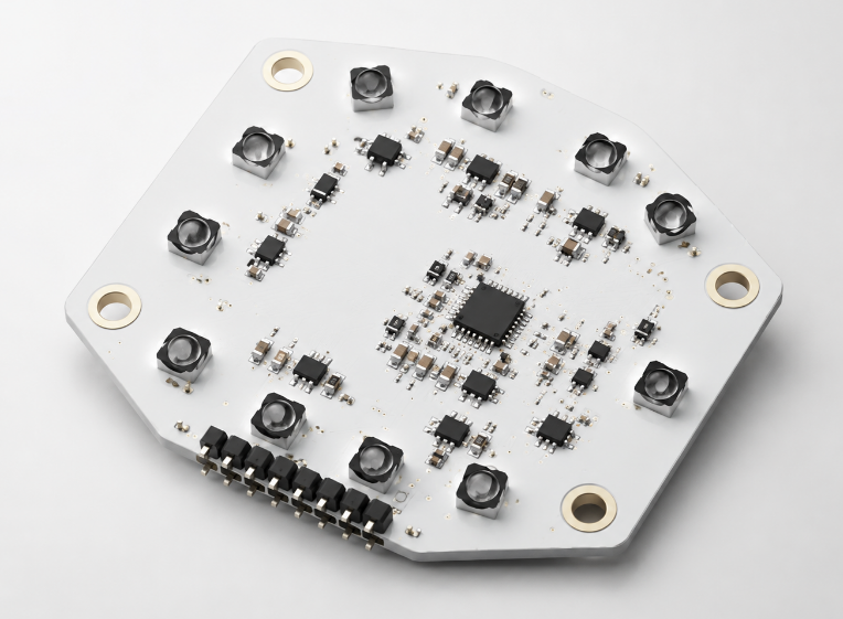
For an occupant monitoring IR LED PCB, divide the camera view into front, rear-center, rear-side, and lower child-seat regions, then assign emitter coverage to those areas.
- Center emitters: Use them to support central cabin areas and deeper rear-seat regions close to the optical centerline.
- Outer emitters: Direct additional IR toward left and right seating positions where off-axis loss is greater.
- Beam overlap: Adjacent emitters should overlap enough to avoid dark gaps, but excessive overlap can create a central hotspot.
- Emitter angle: When package and mechanical design allow it, outer emitters can use a different optical direction from the center LEDs.
- LED spacing: Leave enough PCB area for heat spreading and placement tolerance. Do not compress the array until thermal crowding creates another source of output variation.
- Mechanical alignment: PCB locating features should hold the LED array at a repeatable angle relative to the camera after assembly.
How Should Camera FOV and Seat Geometry Be Matched to the IR Illumination?
The illumination should be designed around the actual cabin area seen by the camera. Camera position, seat locations, and LED beam coverage need to use the same mechanical reference.
- Define the camera coverage first: Use horizontal FOV, vertical FOV, mounting height, and camera tilt to determine which cabin areas appear inside the useful image.
- Map the seating zones inside the FOV: Mark the front passenger, rear-left, rear-center, rear-right, and child-restraint regions. Include seat travel and different occupant heights, because the target position changes with seat adjustment and occupant size.
- Project each LED beam into the same geometry: Check where the center and outer limits of each beam fall relative to the seating zones. An outer seat should not depend only on the weakest edge of one centrally aimed emitter.
- Use beam overlap to remove dark gaps: If one seating zone lies between two weak beam regions, change LED position, emitter angle, or beam width rather than increasing current through the full array.
- Limit illumination outside the useful FOV: IR output falling far outside the monitored cabin region adds electrical load and heat without improving the OMS image.
- Check seat and headrest obstruction: A beam that reaches a rear seat at one front-seat position may be blocked after the seat or headrest moves.
- Check reflective surfaces: Displays, glossy trim, glass, and other reflective surfaces can send concentrated IR back toward the camera. Adjust emitter direction or PCB mounting angle when a strong beam lands directly on one of these surfaces.
The required seating zones should remain inside usable IR coverage across the expected seat-position range.
How Should LED Drive Current and Pulsing Be Set?
LED current and pulse timing should be set from the optical output required at the camera, camera exposure timing, and thermal limits of the selected emitter. The maximum current listed in the datasheet is a device limit, not the normal operating target.
- Set the required optical output first: Determine the illumination needed at the most difficult cabin zones, such as outer or rear seats.
- Select peak current from the emitter operating data: Choose enough current to provide the required radiant output while remaining within the permitted pulsed or continuous operating range.
- Match pulse width to camera exposure: The IR pulse should cover the part of the exposure that needs illumination. A longer pulse increases average power and heat without necessarily improving the captured image.
- Set duty cycle from the repeated pulse pattern: The same peak current can create very different junction temperatures when pulse width or repetition rate changes.
- Decide which LED groups need to operate together: Front, rear, and side zones may not require identical output. Zoned control can reduce unnecessary current and heat.
- Provide driver voltage headroom: The supply must cover LED forward-voltage variation and the voltage required by the current-regulation circuit.
- Control current between equivalent channels: LED groups intended to provide similar illumination should use regulated channels or defined current-setting components rather than uncontrolled parallel current sharing.
Specify peak current, pulse width, repetition rate, duty cycle, active LED groups, and driver supply margin as one approved operating condition.
How Should Thermal Design Control IR LED Junction Temperature?
Thermal design should move heat from the LED package into enough PCB and housing area to keep the emitter within its specified temperature range.
The occupant monitoring IR LED PCB should provide:
- Local copper spreading: Connect the LED thermal pad to enough nearby copper. A narrow connection into a large but distant copper region restricts heat flow.
- Thermal vias with usable receiving copper: Vias can move heat to backside or internal copper, but the destination layer needs enough connected area to spread it.
- PCB construction matched to heat density: Select the substrate and layer structure from LED quantity, drive profile, available board area, and enclosure heat transfer.
- Housing thermal contact: If the enclosure acts as a heat spreader, define the contact area, thermal-interface material, flatness, and mounting method.
- Emitter spacing: Closely packed LEDs share the same local copper and can raise one another’s operating temperature.
A hotter section of the array can produce different optical output even when electrical current is nominally the same, so thermal balance across the board matters as well as maximum temperature.
How Should PCB Current Paths and Driver Placement Keep LED Output Consistent?
The electrical layout should keep comparable LED groups under similar electrical conditions. Voltage drop, uncontrolled current sharing, and local driver heating can create optical variation even when LED placement is correct.
- Current paths: Keep comparable LED supply paths similar in resistance where practical.
- Copper bottlenecks: Avoid narrow pad entries, thin copper necks, or undersized via fields inside otherwise wide power areas.
- Driver placement: Keep each driver close to the LED group it controls so high-current routes remain short.
- Current regulation: Use a driver architecture that controls branch current rather than assuming parallel emitters will divide current equally.
- Driver heat: Avoid placing a hot driver beside only one side of the array, where it can create a local temperature difference.
- LED orientation: Make electrical polarity and optical orientation clear in PCB data, pick-and-place information, and assembly drawings.
What Changes When the OMS Must Support Child Presence Detection?
Child presence detection requires illumination to reach lower and more easily obstructed rear-seat areas in addition to normal adult seating positions.
For an occupant monitoring IR LED PCB, review:
- Lower target height: A child or child-restraint system may sit substantially below an adult head position. Adult-face illumination does not prove that the lower rear-seat region is covered.
- Multiple rear seating positions: Evaluate the required left, center, and right zones individually rather than using one seat as a substitute for the entire rear bench.
- Partial obstruction: Seat wings, headrests, blankets, or another occupant can block part of the direct IR path.
- Different restraint geometry: Child-restraint systems position the head and body at different heights and angles.
- Outer and lower camera regions: These areas need enough IR output without forcing the nearer central seating area into excessive brightness.
Include lower rear-seat zones, child-restraint positions, and partially obstructed locations in the optical coverage map and prototype acceptance test.
How Should the Board Withstand Automotive Temperature, Vibration, and Assembly Variation?
The board should preserve LED position, electrical current, and thermal contact as temperature, vibration, and assembly conditions change.
For the occupant monitoring IR LED PCB:
- Match the LED footprint to the approved package: Land pattern and thermal-pad geometry affect soldering, emitter height, and heat transfer.
- Control PCB stiffness: Excessive board flex can change LED-to-optic spacing and increase solder-joint stress.
- Support connectors and cables: Harness force should not bend the optical region or move the PCB inside the housing.
- Allow for thermal expansion: PCB, housing, optical window, and heat-spreading structures expand differently, so locating features should preserve alignment across the intended temperature range.
- Control critical emitter substitutions: A device with the same footprint may still change the optical result.
- Use repeatable locating features: The PCB should register consistently inside the housing instead of depending only on screw-hole clearance.
A footprint-compatible IR LED should not be approved automatically if its beam angle, wavelength, package height, radiant output, or thermal resistance changes.
What Should Be Verified During Prototype Optical and Electrical Testing?
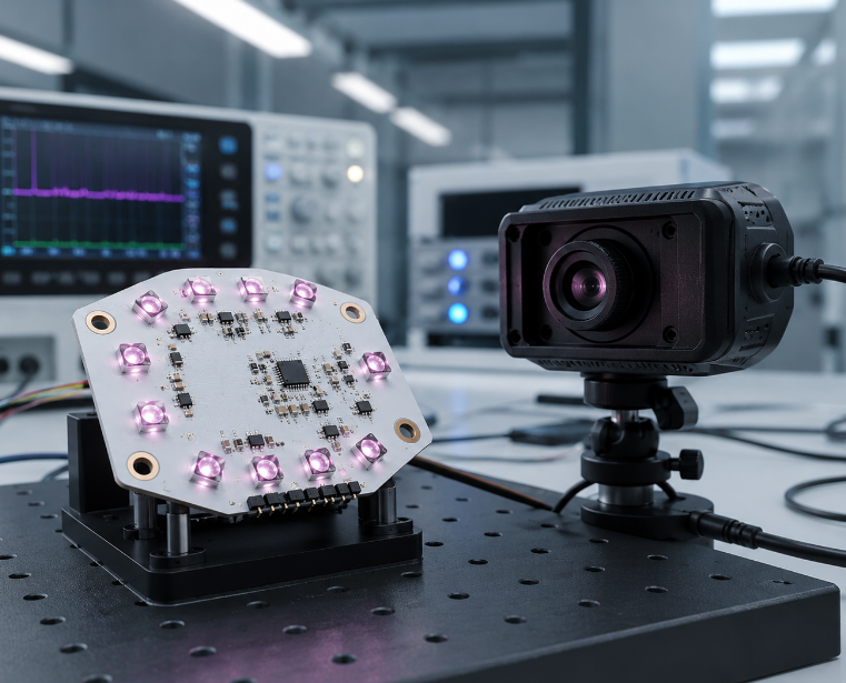
Prototype testing should confirm that the occupant monitoring IR LED PCB produces the required illumination with the real camera, housing, drive settings, and seating geometry.
- LED function and polarity: Confirm every emitter and driver channel operates in the intended orientation and sequence.
- Drive current and pulse timing: Measure peak current, pulse width, duty cycle, and repetition rate at the approved operating states.
- Driver voltage margin: Confirm current regulation remains stable across the required input-voltage range.
- Front and rear coverage: Evaluate the image or irradiance across every required seating zone rather than measuring only the brightest center point.
- Outer and lower coverage: Check side seating and child-restraint regions that are most likely to fall outside the strongest part of the beam.
- Housing influence: Repeat optical measurements with the final window, lens, diffuser, or bezel installed.
- Thermal behavior: Operate the approved drive profile until temperatures stabilize, then check the emitter, driver, PCB, and thermal-interface regions.
- Multiple prototypes: Compare several boards to identify LED variation, placement tilt, current mismatch, or inconsistent thermal contact.
If one seating region remains dark, identify whether the cause is beam direction, obstruction, current, housing loss, PCB alignment, or temperature before increasing current through the entire array.
What DFM and Assembly Controls Matter Before Production?
Production controls should reproduce the same emitter position, electrical path, thermal structure, and optical orientation that passed prototype validation.
For an occupant monitoring IR LED PCB, review:
- LED land pattern and polarity: Verify the footprint against the approved component drawing and make orientation clear in the production data.
- Placement tolerance: Apply tighter placement limits where emitter X-Y position or rotation directly changes beam overlap.
- Thermal-pad stencil: Control solder-paste volume so excessive solder does not tilt or float the emitter.
- Copper and thermal vias: Keep the approved current and heat-spreading structures unchanged unless another engineering review is completed.
- Board flatness: Excessive bow can change LED-to-optic spacing across the array.
- Critical BOM parts: IR LEDs, drivers, current-setting components, connectors, and thermally significant parts should require approval before substitution.
- Inspection access: Leave enough visibility around LEDs and driver packages for placement and solder-joint inspection.
- Traceability: Link PCB revision, BOM revision, assembly data, and required LED bin or lot information to the production batch.
Why Choose EBest Circuit for an Occupant Monitoring IR LED PCB Project?
For an automotive OMS illuminator, the PCB supplier needs to keep the approved optical, electrical, and assembly conditions consistent from prototype through production. EBest Circuit supports PCB design, prototyping, component sourcing, PCB assembly, and mass production within one PCB/PCBA manufacturing workflow.
- Keep the approved prototype configuration intact
Control the PCB construction, LED footprint, copper structure, assembly data, and critical BOM under the same project release. This reduces the risk that production boards differ from the samples used for optical validation. - Control LED placement where beam alignment matters
Define LED position, rotation, PCB dimensions, board flatness, and mounting features in the manufacturing and assembly data so beam overlap remains repeatable when production quantity increases. - Review the PCB structure against the actual IR LED load
Match emitter package, drive conditions, copper area, thermal vias, PCB construction, and enclosure heat transfer before the board is released. - Prevent uncontrolled critical-part substitutions
Identify LEDs, drivers, current-setting components, connectors, and thermally significant parts that require approval before replacement. A same-size component is not automatically an equivalent component when optical, thermal, or electrical characteristics change. - Move from engineering samples into repeat builds with controlled data
EBest Circuit supports both PCB prototyping and mass production, allowing later builds to reproduce the PCB and assembly configuration approved during development. - Support projects with automotive quality requirements
EBest Circuit lists IATF 16949 and ISO 9001:2015 among its certifications, together with ISO 13485:2016 and AS9100D.
For an occupant monitoring IR LED PCB project, send your PCB files, IR LED part number, camera FOV, seating coverage, drive conditions, board dimensions, thermal requirements, and prototype quantity to sales@bestpcbs.com for manufacturing and assembly review.
FAQs About Occupant Monitoring IR LED PCB Design
Q1: Should the IR illuminator be integrated with the camera PCB or built as a separate board?
A1: Both structures are possible. A separate occupant monitoring IR LED PCB allows the illuminator position and thermal path to be adjusted independently from the camera electronics. Integration can reduce connectors and board count when the optical, electrical, and thermal geometry already suit one PCB.
Q2: Can an occupant monitoring IR LED PCB use FR-4?
A2: Yes. FR-4 can be suitable when LED density, duty cycle, available copper, and the enclosure thermal path keep the emitters within the required temperature range. A thermally enhanced construction can be evaluated when heat density rises or available PCB area becomes limited.
Q3: Should a temperature sensor be placed near the IR LEDs?
A3: It can be useful when the system adjusts LED drive according to temperature or records board thermal conditions. Place the sensor where it represents the LED thermal region rather than next to an unrelated hot driver or connector.
Q4: How should IR LED bin variation be controlled?
A4: If wavelength or radiant-output variation affects the camera image, define the approved emitter part number and permitted bin range in the purchasing specification. Unrestricted bin changes should not be introduced after optical validation.
Q5: Can the same occupant monitoring IR LED PCB be used in different vehicle cabins?
A5: The electrical circuit may sometimes be reused, but the optical layout cannot be assumed to transfer directly. Camera position, seat distance, roof height, headrests, trim surfaces, and housing angle can change the required beam direction and overlap, so the illumination pattern should be revalidated for the new cabin.
Q6: Should the PCB include separate test points for each LED channel?
A6: Separate access can simplify current and functional checks when the array contains independently controlled zones. Define test points from the production test method so current, supply, and channel faults can be isolated without probing small LED or driver pins directly.
Q7: How should the IR LED power connector be selected?
A7: The connector and nearby copper should carry the peak LED-array current without excessive voltage drop and tolerate the mechanical load from the harness. Cable force should also be kept away from the LED alignment region.
Q8: Can several high-power IR LEDs be connected directly in parallel?
A8: Direct parallel operation can produce unequal current because LED forward voltage varies between devices and with temperature. Use a current-control architecture that keeps each emitter group within its approved operating range rather than relying on natural current sharing.
Q9: What production information should be traceable?
A9: At minimum, link the PCB revision, BOM revision, critical emitter information, assembly data, and applicable test results to the production build. Additional LED bin or lot traceability can be defined when required by the project.
Q10: What should be frozen after prototype approval?
A10: Freeze the PCB revision, approved IR LED, permitted bin range where applicable, emitter positions and orientation, driver configuration, pulse conditions, thermal structure, housing geometry, and production test limits. Changes affecting these items should receive another engineering review.