A PCB heatsink helps move heat away from high-power components, copper areas, and the circuit board structure so the electronic product can operate within a safe temperature range. In real projects, it is not only a metal part attached to a board. It is part of a complete thermal path that may include copper planes, thermal vias, metal cores, copper coins, thermal interface materials, airflow, enclosure design, and assembly control.
For engineers, the main goal is stable junction temperature. For buyers, the main goal is a manufacturable, repeatable, and cost-controlled thermal solution. A well-designed PCB heatsink can improve reliability in LED lighting, power supplies, motor drives, automotive electronics, telecom modules, industrial control systems, medical electronics, and high-current battery equipment.
What Is a PCB Heatsink?
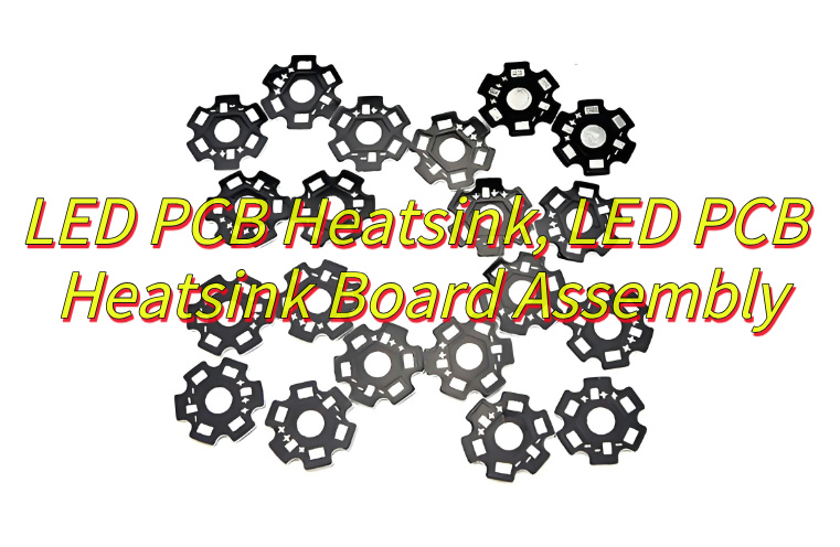
A PCB heatsink is a thermal management structure used to transfer heat from hot components or hot PCB areas into the surrounding environment. It may be a separate aluminum or copper heatsink mounted on the board, or it may be integrated into the PCB through metal core material, thick copper, embedded copper coin, copper base, thermal vias, or bonded heat-conducting plates.
The heat source is usually a power device, LED, MOSFET, diode, regulator, amplifier, processor, resistor, or high-current copper area. When the component generates heat, the PCB heatsink system provides a lower-resistance path for heat to leave the device. Most designs rely on conduction first, then convection, and sometimes radiation.
A simple heatsink may solve moderate heating. A high-power design often needs a combined structure: component pad, thermal via array, copper plane, thermal interface material, heatsink body, screw or clip pressure, and controlled airflow.
Why Does PCB Heatsink Design Matter?
Heat affects electrical performance, component life, solder joint reliability, insulation stability, and enclosure safety. In compact electronics, the board area is smaller while current density and power density continue to rise. This makes thermal planning an early design task, not a final assembly correction.
Poor thermal control may cause LED lumen decay, MOSFET overheating, regulator shutdown, BGA solder fatigue, ceramic capacitor stress, connector discoloration, or local PCB delamination. In high-reliability products, even a small hot spot can shorten service life.
IPC design guidance treats thermal management as part of printed board design considerations, together with material selection, layout, conductor spacing, and manufacturability. IPC-A-610 is also commonly used as an acceptance reference for electronic assemblies, especially when inspecting soldering and assembly workmanship.
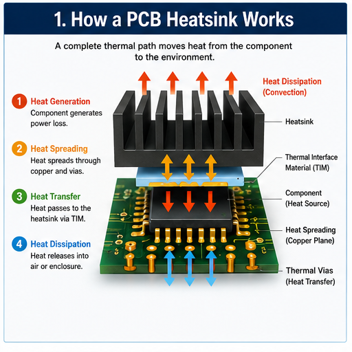
How Does a PCB Heatsink Work?
A PCB heatsink works by creating a controlled heat-transfer path.
| Heat Transfer Stage | What Happens | Design Focus |
|---|---|---|
| Heat generation | Component converts electrical energy into heat | Power loss, current, junction temperature |
| Heat spreading | Heat moves through pads, copper, vias, or substrate | Copper area, via density, metal core, copper coin |
| Heat transfer | Heat enters heatsink through direct contact or TIM | Flatness, pressure, thermal interface material |
| Heat dissipation | Heat leaves the heatsink into air or enclosure | Fin area, airflow, orientation, surface treatment |
| System stabilization | Temperature reaches a working balance | Thermal test, simulation, load condition |
A heatsink normally relies on conduction from the component to the heatsink body, then convection from the heatsink surface to air. Forced airflow improves heat removal, but many industrial and sealed products must use passive cooling. In those designs, the PCB material, copper structure, enclosure metalwork, and external mounting surface become more important.
What Are the Main Types of PCB Heatsink Solutions?
PCB heatsink design has several practical forms. The best choice depends on power loss, board size, available height, airflow, insulation needs, cost target, and production volume.
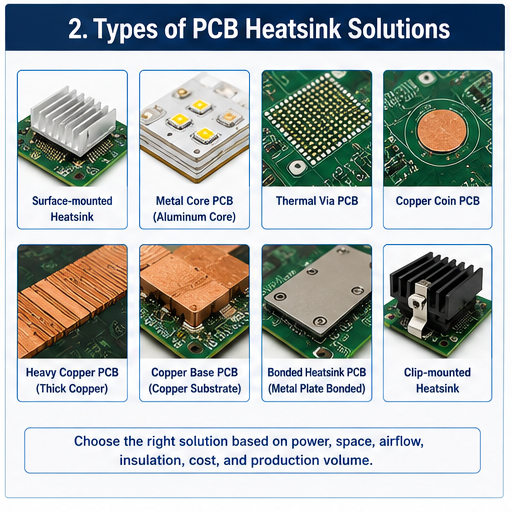
| Type | Typical Structure | Best Used For |
|---|---|---|
| Surface-mounted heatsink | Aluminum or copper part attached above a component | Regulators, processors, MOSFETs, power ICs |
| Through-hole or clip-mounted heatsink | Mechanically fixed heatsink with pins, clips, or screws | Higher vibration or heavier thermal parts |
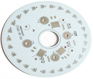
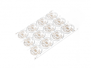
| Metal core PCB | Aluminum or copper substrate under dielectric and copper circuit | LED boards, power modules, lighting products |
| Heavy copper PCB | Increased copper thickness for current and heat spreading | High-current power boards |
| Thermal via PCB | Via array under hot pad connected to copper planes | Compact SMT thermal designs |
| Copper coin PCB | Solid copper insert under high-power component | Local high-heat flux applications |
| Copper base PCB | Copper substrate supports stronger thermal transfer | High-power LED, power conversion, automotive lighting |
| Bonded heatsink PCB | Metal heat plate bonded to PCB | Industrial power and high-temperature assemblies |
A surface heatsink is easier to source and assemble, but it needs board space and mechanical clearance. A metal core or copper base PCB gives better board-level heat spreading, but fabrication control and dielectric selection become more critical. Copper coin technology is useful when heat must move vertically from a small hot component area into a larger thermal mass. Recent industry discussions also highlight embedded copper structures as a strong option for high heat-density boards.
What Materials Are Used for PCB Heatsinks?
The common heatsink materials are aluminum and copper. Aluminum is widely used because it is lightweight, easy to machine or extrude, cost-effective, and suitable for many commercial and industrial designs. Copper has higher thermal conductivity and is useful for compact, high-heat areas, but it is heavier and more expensive.
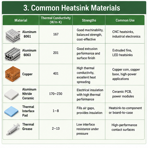
| Material | Strengths | Common Use |
|---|---|---|
| Aluminum 6061 | Good machinability, balanced strength, common industrial use | CNC heatsinks, custom brackets, power electronics |
| Aluminum 6063 | Good extrusion performance and surface finish | Extruded fins, LED heatsinks |
| Copper | Strong thermal conductivity, good local heat spreading | Copper coin, copper base, high-power hotspot control |
| Aluminum nitride ceramic | Electrical insulation with high thermal performance | Ceramic PCB and power module substrates |
| Alumina ceramic | Stable insulation and moderate thermal performance | LED, sensor, and hybrid circuit applications |
| Thermal interface pad | Fills air gaps and supports insulation | Heatsink-to-component or board-to-case contact |
| Thermal grease | Low interface resistance when pressure is controlled | High-performance contact surfaces |
Material choice should not rely on thermal conductivity alone. The full thermal stack includes dielectric thickness, copper thickness, contact resistance, mounting force, surface flatness, and airflow. A high-conductivity heatsink will not perform well if the interface gap is poorly controlled.
PCB Heatsink vs Thermal Vias vs Metal Core PCB
Many buyers ask whether they need a separate heatsink, thermal vias, or a metal core PCB. These options solve related problems, but they are not interchangeable.
| Solution | Main Function | Advantage | Limitation |
|---|---|---|---|
| Separate PCB heatsink | Adds external heat-dissipation area | Flexible, replaceable, suitable for many components | Needs space, mounting control, TIM |
| Thermal vias | Move heat from top layer to inner/bottom copper | Low profile and PCB-integrated | Limited by via structure and copper area |
| Heavy copper | Spreads heat and carries current | Useful for power circuits | Higher fabrication cost and etching control needed |
| Metal core PCB | Transfers heat through board substrate | Good for LED and power boards | Usually less flexible for complex multilayer routing |
| Copper coin PCB | Direct vertical heat path under component | Strong local heat transfer | Requires advanced fabrication control |
| Copper base PCB | Stronger thermal base than aluminum | Excellent for high-power applications | Higher material and machining cost |
For low to moderate power, thermal vias and copper planes may be enough. For LED modules, aluminum PCB or copper substrate may be more practical. For high-current or high-power density devices, copper coin, copper base, or external heatsink structures may be needed.
What Design Parameters Should Be Checked First?
PCB heatsink selection should begin with thermal and mechanical data, not only with a product photo. The following items should be reviewed before choosing the structure.
| Parameter | Why It Matters |
|---|---|
| Power dissipation | Determines heat load that must be removed |
| Maximum junction temperature | Defines safe component operating limit |
| Ambient temperature | Affects final steady-state temperature |
| Board material | Controls heat spreading and insulation performance |
| Copper thickness | Influences current capacity and heat distribution |
| Available board area | Limits heatsink footprint and copper spreading area |
| Component height clearance | Controls heatsink shape and enclosure fit |
| Airflow condition | Separates passive design from forced-air design |
| Electrical insulation | Decides whether insulated pad or dielectric layer is needed |
| Vibration condition | Affects mounting style, screw design, and adhesive choice |
| Assembly process | Impacts soldering, cleaning, TIM application, and inspection |
| Certification target | May affect material, flammability, traceability, and documentation |
Thermal simulation can help at the design stage, but prototype testing is still important. Real products may have heat from nearby components, limited enclosure ventilation, cable obstruction, dust, coating, or uneven mounting pressure.
How to Choose the Right PCB Heatsink Structure?
A practical selection process begins with the heat source and ends with manufacturability.
First, identify the main heat-generating components and calculate their power loss. For MOSFETs, check conduction loss and switching loss. For LEDs, review forward current, voltage, and junction-to-board thermal resistance. For regulators, check input-output voltage difference and output current.
Second, define the thermal path. Heat may move from the component pad into copper planes, through thermal vias, into a bottom-side heatsink, or through a metal substrate into the product housing.
Third, confirm mechanical space. A heatsink that performs well in theory may be unsuitable if it blocks connectors, test points, optical paths, shielding covers, or enclosure screws.
Fourth, review production volume. CNC machining is flexible for prototypes and small batches. Extrusion is efficient for repeated profiles. Die casting may fit high-volume enclosure-linked thermal structures. Stamped or skived fins can be suitable where weight, height, or surface area is critical.
Finally, match the heatsink design with quality control. A custom part must have dimensional tolerance, surface treatment, flatness, burr control, plating or anodizing requirements, and packing protection clearly defined.
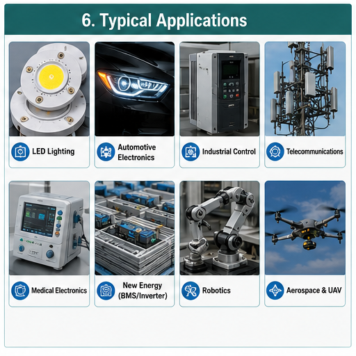
What Industries Use PCB Heatsinks?
PCB heatsinks are used wherever electronic assemblies generate concentrated heat.
| Industry | Common Heat Source | Typical Thermal Solution |
|---|---|---|
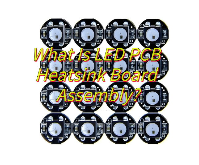
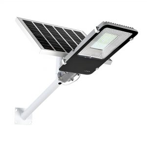
| LED lighting | High-power LED array | Aluminum PCB, copper substrate, external heatsink |
| Automotive electronics | LED headlights, motor drivers, radar modules | MCPCB, copper base PCB, thermal pads |
| Industrial control | Power supply, inverter, relay driver, IGBT/MOSFET | Heavy copper, heatsink, thermal vias |
| Telecommunications | RF amplifier, power module, base station electronics | Copper coin, metal-backed PCB, machined heatsink |
| Medical electronics | Power control, imaging, monitoring modules | Controlled materials, tested assembly, traceability |
| Aerospace and UAV | Motor control, power distribution, RF modules | Lightweight heatsink, high-reliability assembly |
| New energy | BMS, charger, inverter, energy storage control | Heavy copper, copper base, thermal interface control |
| Robotics | Servo drives, compact control boards | Thermal vias, board-to-case heat transfer |
In LED products, the board and heatsink often form one thermal system. In power electronics, the board may need both current-carrying copper and a direct path to chassis or case metal. In RF and telecom designs, the thermal solution must also consider signal integrity, grounding, and shielding.
Practical PCB Heatsink Case Examples
High-Power LED Module
A customer designing an industrial LED light may use an aluminum PCB for cost control. If the current increases or the LED junction temperature remains high, a copper substrate or direct thermal path structure may be considered. The key checks include dielectric thermal conductivity, LED pad flatness, solder voids, screw pressure, and contact quality between the PCB and housing.
Motor Control Board
A motor driver board often uses MOSFETs, shunt resistors, and high-current copper traces. The design may combine heavy copper, large drain copper areas, thermal vias, and a bottom-side heatsink. If vibration is present, screw locking, spacer height, and silicone support should be reviewed.
Telecom RF Power Board
An RF amplifier may need local hotspot control without disturbing impedance-sensitive areas. Copper coin or copper-filled structures can help transfer heat vertically, while the layout must still preserve RF performance. The supplier should review both thermal and electrical design rules before fabrication.
Sealed Industrial Controller
A sealed controller cannot depend on a fan. The board may need to transfer heat into the enclosure through thermal pads or metal standoffs. In this case, the enclosure becomes part of the heatsink. Compression, pad thickness, surface cleanliness, and long-term material stability matter.
Common PCB Heatsink Failure Modes
Thermal problems often appear after assembly, field use, or environmental testing. Many failures come from small process details.
| Failure Mode | Likely Cause | Prevention Method |
|---|---|---|
| Hot component still overheats | Thermal path not continuous | Review pad, via, copper, TIM, and heatsink contact |
| Heatsink becomes loose | Weak adhesive or poor mechanical fixing | Use screws, clips, staking, or qualified adhesive |
| Solder joint fatigue | Thermal cycling and mechanical stress | Improve heat spreading and reduce heatsink weight load |
| PCB discoloration | Local temperature too high | Increase copper area, use better substrate, improve airflow |
| Poor insulation | Wrong thermal pad or damaged dielectric | Confirm voltage rating and pad placement |
| High temperature variation | Uneven pressure or warped surface | Control flatness, screw torque, and pad compression |
| Corrosion or oxidation | Unsuitable surface finish or environment | Select proper anodizing, plating, coating, or sealing |
| Assembly interference | Heatsink blocks components or test access | Check 3D model before tooling |
For Class 2 and Class 3 products, inspection requirements and workmanship control should be defined before production. IPC-A-610 is widely referenced for assembly acceptance criteria, while UL 94 is often considered when evaluating material flammability behavior in electronic products.
What Affects PCB Heatsink Cost?
PCB heatsink cost is influenced by both the metal part and the PCB thermal design.
| Cost Factor | Impact |
|---|---|
| Material | Copper costs more than aluminum; ceramic substrates cost more than FR4 |
| Manufacturing process | Extrusion, CNC, die casting, skiving, stamping, and bonding have different tooling needs |
| Tolerance | Tight flatness, hole position, and surface finish increase process control |
| Surface treatment | Anodizing, plating, passivation, or coating adds cost |
| Volume | Tooling can reduce unit cost when quantity is stable |
| Assembly method | Screws, clips, pads, grease, adhesive, and manual work affect labor cost |
| Testing | Thermal testing, X-ray, electrical test, and reliability testing add value and cost |
| Documentation | Traceability, inspection reports, and compliance files require extra control |
The lowest-cost design is not always the best-value design. A slightly higher substrate cost may reduce heatsink size. A better interface pad may improve repeatability. A clearer mechanical design may reduce assembly labor and rework. Cost should be reviewed at system level, not only part level.
How Is PCB Heatsink Quality Controlled?
Quality control should cover design review, incoming material inspection, fabrication, assembly, and final testing.
For PCB fabrication, important checks include copper thickness, dielectric thickness, drill quality, plating integrity, solder mask registration, surface finish, and electrical test. For heatsink parts, checks include dimension, flatness, hole position, burrs, surface treatment, cleanliness, and packing.
For assembly, operators should control thermal pad placement, grease amount, screw torque, clip pressure, adhesive curing, and component clearance. For high-power products, thermal testing under load is strongly recommended. X-ray inspection may be used to check solder voids under thermal pads, BGAs, power packages, or large bottom-terminated components.
RoHS compliance may also be required for products entering regulated markets because the EU RoHS Directive restricts hazardous substances in electrical and electronic equipment.
How to Choose a PCB Heatsink Supplier?
A reliable supplier should understand both PCB manufacturing and thermal assembly. A metal heatsink supplier may know machining, but may not understand PCB stack-up, copper balance, soldering limits, creepage, insulation, and SMT assembly. A PCB factory may understand board fabrication, but may not always support mechanical heatsink integration.
For B2B buyers, the better choice is often a manufacturer that can review Gerber files, BOM, PCB stack-up, mechanical drawings, thermal drawings, and assembly requirements together.
Before placing an order, check whether the supplier can support:
| Supplier Capability | Why It Matters |
|---|---|
| DFM review | Finds thermal, mechanical, and assembly risks early |
| PCB fabrication | Controls copper, dielectric, vias, and stack-up |
| PCBA assembly | Ensures heatsink does not conflict with SMT/THT process |
| Component sourcing | Helps match thermal package and availability |
| Mechanical part support | Coordinates heatsink drawing, tolerance, and surface finish |
| Testing | Verifies electrical and thermal performance |
| Traceability | Supports regulated and long-life products |
| Prototype to mass production | Reduces design transfer risk |
A China-based source factory can be a strong option for custom PCB heatsink projects when the buyer needs engineering communication, flexible customization, prototype support, batch production, and global shipment without unnecessary trading layers. The key is to verify real manufacturing capability, not only a product catalog.
What Should Be Checked Before Ordering?
Before sending RFQ, prepare a complete technical package. This reduces back-and-forth communication and improves quotation accuracy.
| File or Requirement | Recommended Detail |
|---|---|
| Gerber files | Final PCB production data |
| BOM | Component part numbers, package, power rating |
| Pick-and-place file | Coordinates and rotation for assembly |
| Stack-up requirement | Material, thickness, copper weight, dielectric |
| Mechanical drawing | Heatsink size, holes, height, tolerance |
| Thermal target | Power dissipation, ambient temperature, max surface temperature |
| Interface material | Pad, grease, adhesive, insulation requirement |
| Surface finish | ENIG, HASL, OSP, immersion silver, or others |
| Compliance | RoHS, UL, IPC class, customer-specific standard |
| Testing plan | E-test, AOI, X-ray, functional test, thermal test |
| Quantity and schedule | Prototype, pilot run, mass production |
| Packing requirement | Anti-static, scratch protection, export packing |
A strong supplier will not only quote the price. They should also ask about temperature rise, airflow, enclosure contact, insulation, and assembly method when the design has obvious thermal risk.
FAQ About PCB Heatsink
What is the purpose of a PCB heatsink?
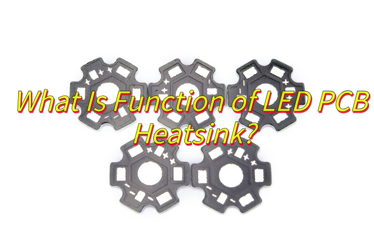
A PCB heatsink removes heat from components or hot board areas and transfers it to air, enclosure metal, or another cooling surface. It helps maintain safe operating temperature, improve component life, and reduce field failures caused by overheating.
Is a PCB heatsink always required?
No. Some boards can control heat through copper planes, thermal vias, component spacing, or airflow. A heatsink becomes necessary when these methods cannot keep components within the required temperature limit during real operating conditions.
Which is better for PCB heatsink, aluminum or copper?
Copper offers stronger thermal conductivity, while aluminum is lighter, easier to process, and more cost-effective. Aluminum is common for external heatsinks. Copper is often selected for copper coins, copper base PCBs, and compact high-heat areas.
Can FR4 PCB use a heatsink?
Yes. FR4 boards can use surface-mounted or mechanically fixed heatsinks. However, FR4 has limited thermal conductivity compared with metal core or ceramic substrates, so thermal vias, copper planes, and interface materials should be carefully designed.
What is the difference between MCPCB and PCB heatsink?
An MCPCB uses a metal core as part of the board structure, while a PCB heatsink may be an external metal part attached to a standard or special PCB. Many LED and power products use both concepts together.
What is a copper coin PCB?
A copper coin PCB uses a solid copper insert under a high-power component to create a direct heat path through the board. It is useful for localized hotspots where normal vias and copper planes may not remove heat fast enough.
Do thermal vias replace a heatsink?
Thermal vias can reduce local temperature by transferring heat between layers, but they do not always replace a heatsink. If total power is high or airflow is weak, the design may still need an external heatsink or metal base.
What thermal interface material should be used?
Thermal pads are useful when insulation, gap filling, and easier assembly are needed. Thermal grease can provide strong contact performance but requires controlled application. The choice depends on voltage, pressure, surface flatness, and rework needs.
How do you test PCB heatsink performance?
Testing usually includes temperature measurement under rated load, thermal camera review, thermocouple placement, functional testing, and sometimes chamber testing. The product should be tested in its real enclosure or a setup close to final use.
Why does a heatsink still fail after installation?
Common causes include poor contact, insufficient mounting pressure, wrong pad thickness, warped surfaces, blocked airflow, solder voids, or underestimated power loss. The full heat path must be checked instead of only increasing heatsink size.
Can a PCB heatsink be customized?
Yes. Custom PCB heatsinks can be designed by material, size, fin shape, hole position, surface treatment, and mounting style. Customization is common in power electronics, LED lighting, automotive modules, and industrial control equipment.
What information is needed for a PCB heatsink quotation?
A supplier usually needs PCB files, BOM, mechanical drawings, power data, target temperature, operating environment, quantity, surface finish, compliance requirements, and assembly method. More complete data leads to a more accurate quotation.
Conclusion:
A PCB heatsink should be selected as part of the complete thermal system, not as an isolated metal accessory. The right design depends on power loss, board material, copper structure, component package, airflow, enclosure contact, insulation, assembly pressure, and production volume.
For general projects, aluminum heatsinks, thermal vias, and copper planes may provide a practical balance of cost and performance. For higher power density, copper base PCB, heavy copper PCB, copper coin structures, metal core PCB, ceramic PCB, or board-to-case thermal transfer may be more suitable.
At EBest Circuit (Best Technology), we support PCB fabrication, PCBA assembly, DFM review, component sourcing, thermal design optimization, testing, and custom engineering solutions for prototype and mass production projects.
If you are working on a PCB heatsink, metal core PCB, copper base PCB, high-power LED PCB, power electronics board, or custom thermal management project, our engineering team can help review your design and provide practical manufacturing suggestions. Email: sales@bestpcbs.com