A reliable boiler PCB helps appliance manufacturers avoid no-start failures, intermittent shutdowns, repeated service calls, delayed approvals, and costly board revisions. Reducing these risks before the first build means reviewing the PCB data, BOM, assembly drawings, operating environment, programming instructions, and acceptance tests as one complete manufacturing package.
EBest Circuit (Best Technology) gives engineering and purchasing teams one coordinated path from approved files to a controlled prototype or production build. We support DFM review, PCB fabrication, component sourcing, PCBA assembly, inspection, and customer-defined testing coordination. The customer remains responsible for the boiler’s system architecture, firmware, combustion-safety logic, and finished-appliance certification.
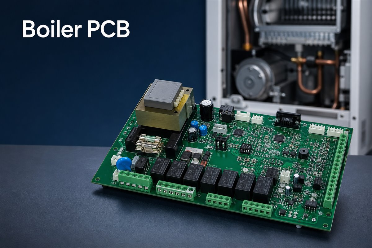
What Is a Boiler PCB?
A misunderstanding at the specification stage can cause buyers to source the wrong board type or compare quotations that do not include the same work. A boiler PCB is the printed circuit board—or, more commonly in practical sourcing, the assembled PCBA—that connects and controls the electronic functions defined by the boiler designer.
Depending on the system, the assembly may interface with temperature and pressure sensors, pumps, fans, valves, ignition-related circuits, displays, communication modules, and power supplies. It can contain low-voltage logic, mains-connected sections, relays, transformers or isolated power components, connectors, protection devices, and programmed control devices on the same assembly.
The term is often used loosely. Buyers should separate the following scopes before comparing quotations:
| Requested product | What it normally includes | What the buyer should confirm |
| Bare boiler PCB | Copper circuitry, solder mask, silkscreen, surface finish, and mechanical features | Stackup, copper, finish, tolerances, slots, and testing |
| Boiler PCBA | Bare PCB plus soldered electronic components | BOM, placement data, assembly drawings, inspection, and acceptance criteria |
| Programmed and tested PCBA | Assembled board plus agreed programming and test operations | Firmware revision, fixture, test limits, records, and failed-unit handling |
Buyers should also state whether components are consigned by the customer, sourced by the supplier, or handled through a mixed purchasing model. This prevents a low bare-board quotation from being compared with a turnkey PCBA quotation that includes sourcing, programming, and testing.
A boiler PCB is also part of the wider HVAC circuit board family, but its exact interfaces and operating sequence depend on the boiler platform. That is why manufacturing requirements should come from the customer’s approved design files and product risk assessment rather than from a generic “boiler board” specification.
How Does a Boiler PCB Control the Heating Sequence?
An unclear sequence can create false fault reports because a manufacturing problem and a system-design problem may look similar during final testing. In a typical application, the board reads input conditions, applies the control logic supplied by the OEM, switches defined outputs, and monitors feedback to decide whether the sequence may continue.
For example, a heating request may require the controller to perform a sequence such as:
- Read the required sensor and interlock states.
- Energize a pump, fan, or other defined output.
- Operate an ignition-related output according to the approved firmware.
- Monitor the expected feedback within the specified time.
- Continue, stop, or lock out according to the customer’s control logic.
The exact order, timing, thresholds, and safety responses are product-specific. They should be defined and validated by the boiler manufacturer—not assumed by the PCBA supplier.
From a manufacturing perspective, this sequence becomes useful test information.
The customer should define:
- which inputs must be simulated;
- which outputs must be measured;
- which firmware and configuration revision must be loaded;
- the expected timing and measurement limits;
- what constitutes a pass, failure, or retest condition.
Without this information, a supplier may confirm workmanship and electrical continuity but cannot independently prove that the assembly performs every intended boiler function.
Before quotation, the project package should therefore explain whether the supplier is expected to provide unprogrammed assemblies, load customer firmware, run a fixture-based functional test, or support final testing in the customer’s product.
Which Boiler PCB Types Require Different Manufacturing Decisions?
Treating every boiler board as the same can lead to the wrong material, component, assembly, coating, or test assumptions. The manufacturing plan should reflect how the board is used and where its main risks are concentrated.
Common application differences include:
- Gas-boiler control boards with ignition-related interfaces, valve and fan outputs, flame-detection circuitry, and strict system safety requirements.
- Electric-boiler boards with significant heater-control loads, contactors, relays, current sensing, and thermal-management concerns.
- Combi-boiler controllers coordinating space heating and domestic hot-water functions.
- Condensing-boiler electronics operating in equipment where moisture management and enclosure airflow require careful review.
- Interface or display boards that may carry lower power but face connector, handling, and human-interface demands.
- Communication or expansion boards connecting the appliance to thermostats, building controls, or service tools.
These categories do not automatically determine a laminate, copper weight, coating, or test method. A compact display board and a mains-switching control board may need very different stackups and process controls even when installed in the same boiler. The customer should provide rated voltages and currents, isolation requirements, operating environment, board location, mechanical constraints, expected service life, and applicable product standards.
EBest Circuit can review whether the supplied fabrication and assembly package communicates those requirements consistently. Any change to the electrical architecture or safety function must be approved by the customer’s responsible engineers.
What Causes Boiler PCB Failures?
Field returns become expensive when the team replaces a board without identifying whether the root cause came from design margin, component selection, assembly variation, installation stress, contamination, or another part of the boiler. A useful failure review separates the observed symptom from the physical mechanism.
Common PCB and PCBA failure mechanisms include:
- Solder-joint cracking around relays, transformers, terminal blocks, and other heavy or mechanically loaded parts.
- Local overheating at relays, power resistors, connectors, copper bottlenecks, or poorly cooled components.
- Corrosion or leakage paths caused by condensation, ionic contamination, or unsuitable coating coverage.
- Intermittent connections caused by fretting, weak connector retention, cable strain, or repeated thermal cycling.
- Incorrect component value, polarity, package, or approved-vendor substitution.
- Insufficient spacing or contamination across high-voltage and low-voltage regions.
- Firmware, programming, or configuration mismatch between otherwise identical-looking assemblies.
- Damage introduced by handling, electrostatic discharge, mounting stress, or enclosure interference.
A production supplier can help investigate workmanship, material records, component traceability, inspection evidence, and test results. However, a no-heat or lockout symptom does not by itself prove that the PCB is defective. Sensors, wiring, pumps, fans, valves, power quality, firmware, and other system conditions may produce similar symptoms. Troubleshooting gas or mains-powered boilers should be performed by appropriately qualified personnel.
For new projects, the best action is to convert known failure risks into drawing notes, BOM controls, inspection points, and test criteria before production begins.
How Can Boiler PCB Reliability Be Improved?
Reliability improves when the project prevents predictable stresses instead of relying on final inspection to find damage after it occurs. Heat, moisture, vibration, contamination, and handling should be translated into specific design inputs and manufacturing controls.
Focus the reliability review on three stress groups:
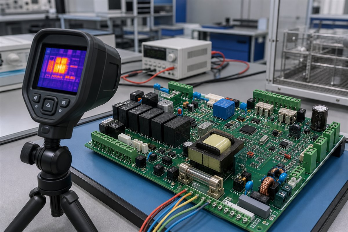
- Heat: Identify high-loss components and realistic current conditions. Review copper width, copper weight, thermal vias, component spacing, airflow, enclosure temperature, and component ratings against the approved design. Thermal images or measured temperatures from an engineering sample are more useful than a general request for a “high-temperature PCB.”
- Moisture and contamination: Define the expected condensation, contamination, and cleaning environment. Conformal coating can help in suitable applications, but it is not a universal cure. The coating must be compatible with the PCB surface, components, operating temperature, service process, and product requirements. A masking drawing should identify connectors, test points, switches, heat sinks, and other no-coat areas. Cleanliness and curing also matter because coating over contamination can trap the problem.
- Vibration and mechanical stress: Provide adequate support, hole and pad geometry, solder-joint design, and spacing for heavy components. Review connector insertion force, cable pull, depaneling stress, screw torque, and enclosure fit. If adhesive, staking, or other retention is required, document its material, location, height, and acceptance standard.
These controls should be tied to measurable drawings, samples, or test requirements. Phrases such as “high reliability” or “moisture resistant” are not enough for repeatable production.
EBest Circuit can review these requirements for manufacturability and process consistency. Environmental validation and lifetime targets must still be defined and approved by the OEM.
How Should Power and Control Circuits Be Separated?
Poor separation can expose low-voltage logic to noise, leakage, arcing, or unsafe energy. It can also make inspection difficult if the project files do not clearly distinguish circuit domains.
The design team should identify mains, high-current, isolated, protective-earth, sensor, communication, and logic areas. Creepage and clearance values must be selected from the product’s applicable safety requirements, working voltage, insulation system, pollution degree, material group, altitude, and other relevant conditions. A generic spacing copied from another board is not a substitute for a product-specific compliance decision.
Before releasing the data, confirm:
- required creepage and clearance dimensions;
- isolation slots, barriers, and keep-out areas;
- copper width and current requirements for load paths;
- fuse, relay, connector, and protection-device ratings;
- grounding and protective-earth instructions;
- test voltages and which nets or regions they apply to;
- coating or potting effects that are recognized by the applicable standard;
- silkscreen, assembly, and inspection markings that help prevent mistakes.
DFM review can flag narrow spacing, small isolation slots, copper-to-edge risk, solder-mask concerns, and manufacturing tolerances that may reduce the intended separation. It cannot decide the finished boiler’s required insulation architecture on the customer’s behalf. When a rule affects safety, the controlling value should come from the customer’s authorized engineering and compliance documentation.
What Should Engineers Check Before PCB Fabrication?
Missing or conflicting files often create more delay than the actual board fabrication. A quotation based only on Gerber files may omit component sourcing, programming, special assembly, coating, fixtures, or acceptance-test costs.
A controlled release package should normally include:
- Gerber or ODB++ data and drill files.
- Fabrication drawing with stackup, finished thickness, copper, surface finish, tolerances, slots, cutouts, and controlled-impedance requirements where applicable.
- BOM with manufacturer part numbers, approved alternatives, do-not-substitute items, and sourcing responsibility.
- Pick-and-place data and assembly drawings showing polarity, orientation, reference designators, and special installation notes.
- Panelization, breakaway, edge-clearance, and tooling requirements when these are customer-controlled.
- Firmware files, programming method, device configuration, checksums, and version-control instructions when programming is required.
- Coating, adhesive, masking, cleaning, and cosmetic requirements.
- Test specification, fixture interface, expected readings, pass limits, and failure-record requirements.
- Golden sample or approved photographs when visual details cannot be communicated reliably by drawings alone.
The files should carry matching revisions. If the BOM is revision C while the assembly drawing is revision B, production can follow two individually valid documents and still build the wrong result. A formal release checklist and written resolution of engineering questions reduce that risk.
EBest Circuit can provide a DFM review and BOM optimization list within the supplied project scope. The customer should approve substitutions, functional changes, and any deviation from the released design before procurement or production.
How Are Boiler PCB Assemblies Inspected?
Inspection gaps allow a visually acceptable board to reach functional testing with the wrong component, weak solder joint, missing operation, or undocumented rework. A suitable inspection plan combines process evidence instead of depending on one machine or one final visual check.
A practical inspection flow may include:
- Incoming verification: Check PCB identity, component labels, quantities, moisture-sensitive handling, date or lot information, and selected high-risk parts.
- Solder-paste control: Use solder-paste inspection when the package mix and process risk justify it.
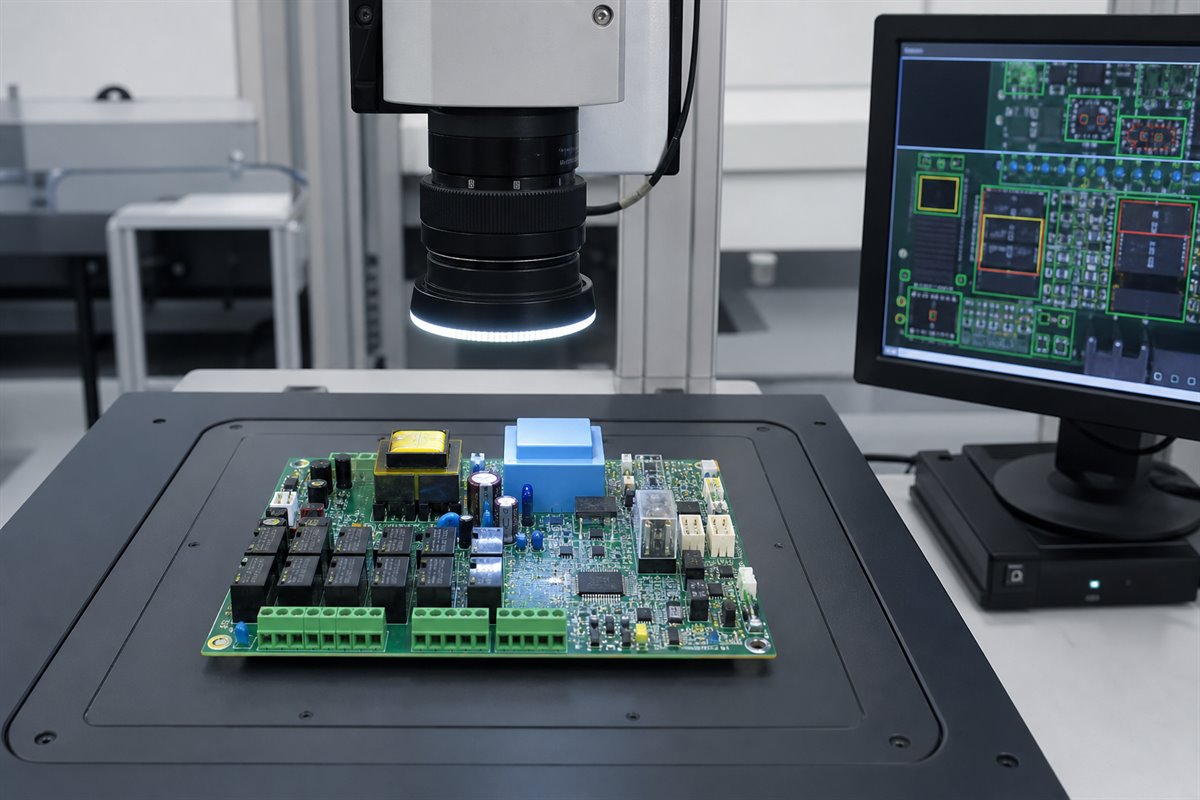
- Placement and solder inspection: Use automated optical inspection to check placement, polarity, solder appearance, and component presence.
- Hidden-joint inspection: Select X-ray for bottom-terminated or other concealed joints where it adds useful coverage; it is not required for every package or board.
- Manual process inspection: Check connectors, terminal blocks, relays, transformers, through-hole soldering, coating boundaries, adhesive, and mechanical hardware.
- First-article confirmation: Compare the initial assembly with the BOM, drawings, approved sample, and special requirements before the full batch proceeds.
No inspection method proves every electrical or functional requirement. The control plan should be based on component packages, process risks, customer requirements, and the consequences of an escape. Inspection records should also connect to the batch and revision so that a later question can be traced to the correct material and production history.
What Testing Should Be Defined Before Production?
Undefined testing creates two opposite risks: the supplier may perform only basic workmanship checks, or the quotation may assume a complex test that the customer did not budget or provide data for. The test level should be agreed before the order.
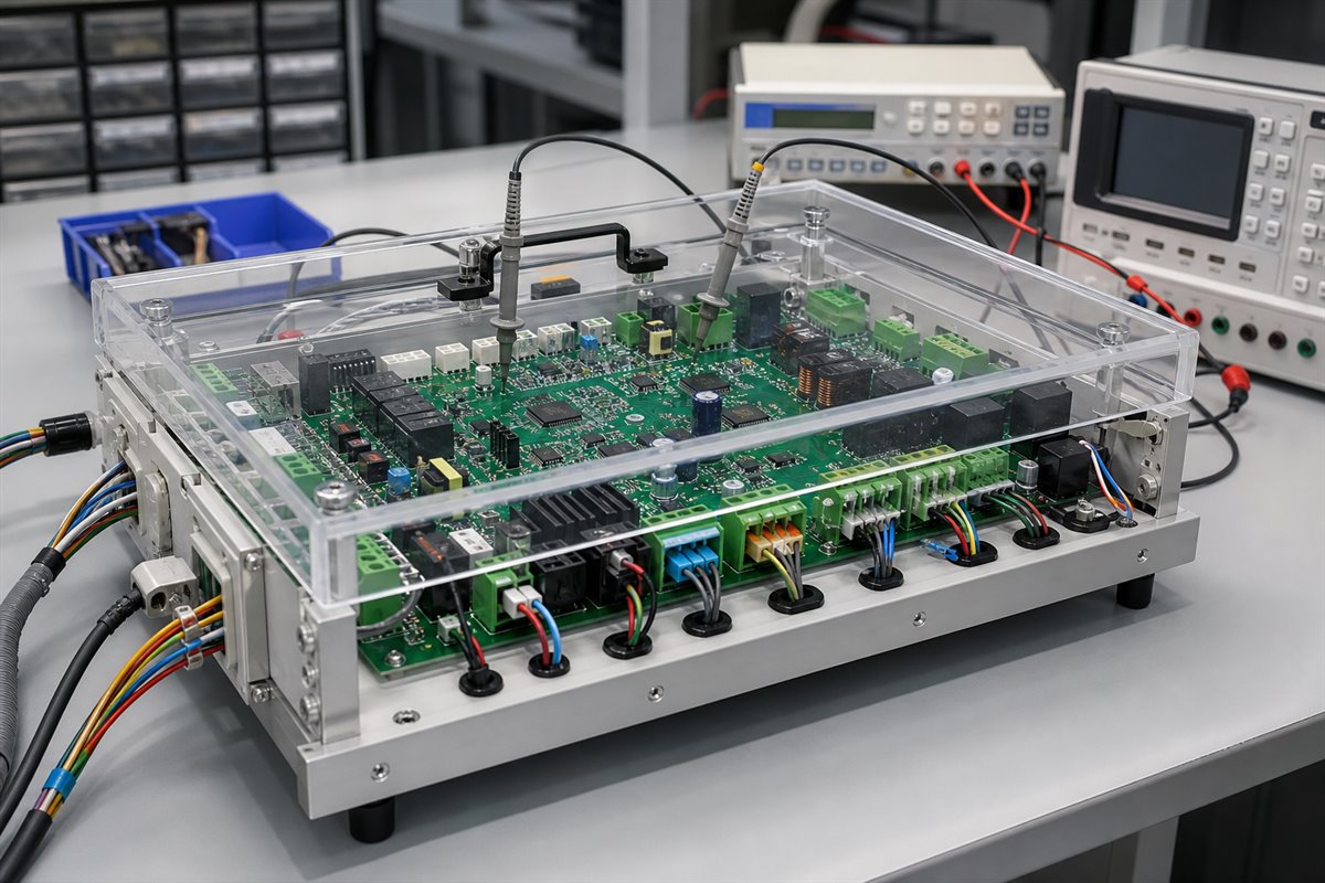
Bare-board electrical testing checks PCB continuity and isolation against the supplied net data. After assembly, automated or fixture-based checks may verify selected components, shorts, opens, programmed devices, voltage rails, communication, and controlled input/output behavior. The exact method depends on access, volume, fault coverage, product risk, and available customer data.
For a functional test, the OEM should define safe simulated inputs, expected outputs, timing or measurement limits, firmware revision, connection method, and handling of failed units. If mains or load simulation is involved, fixture safety and operator protection require particular attention. A PCBA supplier should not invent combustion or appliance-safety acceptance limits.
Useful test-release questions include:
- Which faults must the test detect?
- Which nets and interfaces are accessible?
- Is programming performed before or during the test?
- Are real loads, simulated loads, or a customer-supplied appliance required?
- What are the numeric pass limits and allowed tolerances?
- How are results linked to the PCB serial number or batch?
- Who approves fixture changes and test-software revisions?
Answering these questions early helps the supplier estimate fixture effort, cycle time, coverage, and responsibilities accurately.
How Do Prototype Builds Reduce Boiler PCB Risk?
Moving directly from released files to a large order can multiply a small documentation or assembly error across the whole batch. A prototype or pilot build gives the engineering team a controlled point to verify the board, assembly process, programming, mechanical fit, and test method before volume commitments.
A practical pilot-build flow is:
- Review DFM findings, BOM risk, and unresolved engineering questions.
- Purchase a controlled quantity of approved material.
- Assemble and inspect the first article before continuing the batch.
- Verify component orientation, solderability, connector alignment, and enclosure clearance.
- Confirm firmware loading, fixture access, coating masks, and defined functional behavior.
- Record issues and close them through an approved revision or deviation process.
Consider an illustrative boiler-controller project containing relays, terminal blocks, a programmed controller, temperature-sensor inputs, and a communication connector. During the first build, the supplier may discover that a connector drawing does not define the mating-cable exit direction, a relay alternative has a different height, or a test point becomes inaccessible after the board is installed. Resolving those items before the repeat order avoids enclosure rework, purchasing confusion, and incomplete production testing. This example describes a realistic workflow, not a claim about a specific customer project.
EBest Circuit supports prototype PCB assembly and small-quantity PCB and PCBA builds for engineering validation. Prototype approval should record the final files, BOM decisions, firmware, test revision, and open issues so that the next batch repeats the approved build rather than an earlier version.
How Does EBest Circuit Support Boiler PCB Projects?
Coordinating separate PCB, component, assembly, and test suppliers can slow engineering communication and make responsibility unclear when files change. EBest Circuit (Best Technology) provides one-stop support covering PCB manufacturing, component sourcing, PCBA assembly, inspection, and testing coordination for customer-owned boiler PCB designs.
Our service model combines one sales contact with engineering support across the project.
Project support can include:
- DFM review before fabrication and assembly;
- BOM review for sourcing risk, package conflicts, long-lead items, and customer-approved alternatives;
- PCB fabrication and component purchasing coordination;
- SMT, through-hole, and mixed PCBA assembly as required by the approved data;
- inspection and traceability aligned with the project requirements;
- programming and customer-defined test coordination when files and criteria are available;
- prototype and small-batch builds before production scaling.
EBest Circuit operates PCB and PCBA manufacturing resources, works with an established component supply network, and supports traceability of materials, batches, and production progress. Company quality-system certifications include ISO 9001, ISO 13485, IATF 16949, and AS9100D. The applicable process, documentation, and certification requirements for each boiler project must be confirmed during quotation; these company certifications do not replace finished-boiler approval.
To request a manufacturing review, send Gerber files, BOM, pick-and-place data, assembly drawings, expected quantity, application requirements, and test instructions to sales@bestpcbs.com. Our team can then identify open questions and prepare a quotation around the actual project scope.
FAQs About Boiler PCBs
What is the difference between a boiler PCB and a general HVAC control board?
A boiler PCB is an HVAC-related control board developed for a particular boiler platform and its defined sensors, outputs, loads, communications, and operating sequence. “HVAC control board” is a broader term that also covers air conditioners, furnaces, heat pumps, ventilation equipment, and other systems. Manufacturing requirements should follow the specific product files rather than the category name alone.
What files are needed to manufacture a boiler PCB assembly?
A typical turnkey package includes Gerber or ODB++ data, drill files, fabrication drawing, BOM with manufacturer part numbers, pick-and-place data, assembly drawings, and quantity. Add firmware and programming instructions, coating or masking drawings, mechanical requirements, test specifications, and an approved sample where applicable. All documents should have consistent revision control.
Does a boiler PCB need conformal coating?
Not automatically. The decision depends on condensation, contamination, component compatibility, temperature, serviceability, enclosure protection, and applicable product requirements. If coating is specified, the customer should define the material or performance requirement, thickness where relevant, no-coat areas, cleanliness, cure, inspection, and test expectations.
How should relay and connector loads be tested?
The OEM should define the rated and worst-case loads, switching conditions, duty cycle, temperature limits, acceptable voltage drop, contact behavior, connector requirements, and pass criteria. Prototype testing may combine electrical measurements, temperature checks, repeated switching, and inspection. The method must reflect the actual circuit and product risk; it should not be replaced by a generic relay test.
Can boiler PCB assemblies be built in small batches before volume production?
Yes. A prototype or small batch can validate component availability, assembly workmanship, programming, mechanical fit, coating, inspection, and customer-defined functional testing before volume production. The approved pilot configuration should then be frozen through controlled files, BOM decisions, firmware records, and test documentation.
Need to move a boiler PCB from engineering files to a controlled prototype or production build? Send your Gerber files, BOM, pick-and-place data, assembly drawings, quantity, coating requirements, and test instructions to sales@bestpcbs.com. EBest Circuit (Best Technology) can review manufacturability and sourcing risks, then support PCB fabrication, component procurement, PCBA assembly, inspection, and customer-defined testing coordination within the agreed project scope.