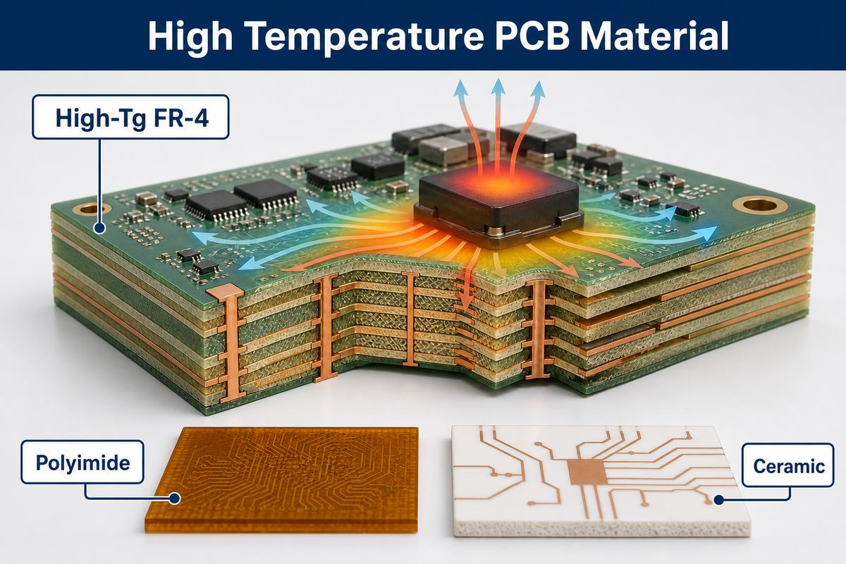
A high temperature PCB material must do more than survive one hot assembly cycle. It needs to maintain insulation, dimensional stability, copper adhesion, and plated-hole reliability throughout the product’s real thermal profile. The correct choice depends on operating temperature, dwell time, cycling rate, heat flow, voltage, frequency, stackup, and expected service life.
At EBest Circuit, we manufacture high-Tg FR-4 and work with polyimide, high temperature ceramic substrate, and selected high-performance laminate systems for demanding PCB applications. We begin with the actual environment rather than selecting the highest Tg on a datasheet. This prevents both under-specification and unnecessary material cost. For an initial material review, you can send the stackup, operating and peak temperatures, Gerber files, copper requirements, quantity, and test conditions to sales@bestpcbs.com.
What Is a High Temperature PCB Material?
A high-temperature material is a laminate or substrate that retains the required electrical and mechanical properties under a defined thermal load. That definition is intentionally application-specific. A board that sees three lead-free reflow cycles has a different exposure from an industrial controller operating near a furnace for years.
Engineers should separate three temperature cases:
- Assembly peaks: short soldering and rework excursions.
- Continuous operation: the steady temperature near the board or component.
- Thermal cycling: repeated movement between low and high temperatures.
The weakest part of the finished structure may be the resin, copper interface, plated hole, solder joint, coating, connector, or component rather than the laminate itself. A reliable material specification therefore starts with the complete use profile, not a single headline temperature.
Which Properties Matter Beyond Tg?
Tg, or glass transition temperature, is the region where a resin changes from a rigid glassy state to a softer state with faster expansion. It helps classify resin systems, but it is not the board’s continuous-use rating.
The following properties provide a more complete picture:
| Property | What It Indicates | Why It Matters |
|---|---|---|
| Tg | Resin transition region | Dimensional stability and expansion behavior |
| Td | Onset of chemical decomposition under the stated test method | Resistance to severe thermal exposure |
| T260/T288 | Time to delamination at a specified temperature | Assembly and rework robustness |
| Z-axis CTE | Expansion through board thickness | Stress on plated holes and vias |
| Thermal conductivity | Rate of heat movement through material | Junction temperature and heat spreading |
| Moisture absorption | Water uptake under test conditions | Reflow defects and insulation stability |
| Dk and Df | Dielectric behavior and loss | Impedance, timing, and RF/high-speed performance |
Compare values only when the test method, material thickness, resin content, and conditioning are compatible. A higher Tg does not guarantee lower Z-axis expansion, better heat transfer, or lower signal loss.
High Temperature PCB Materials
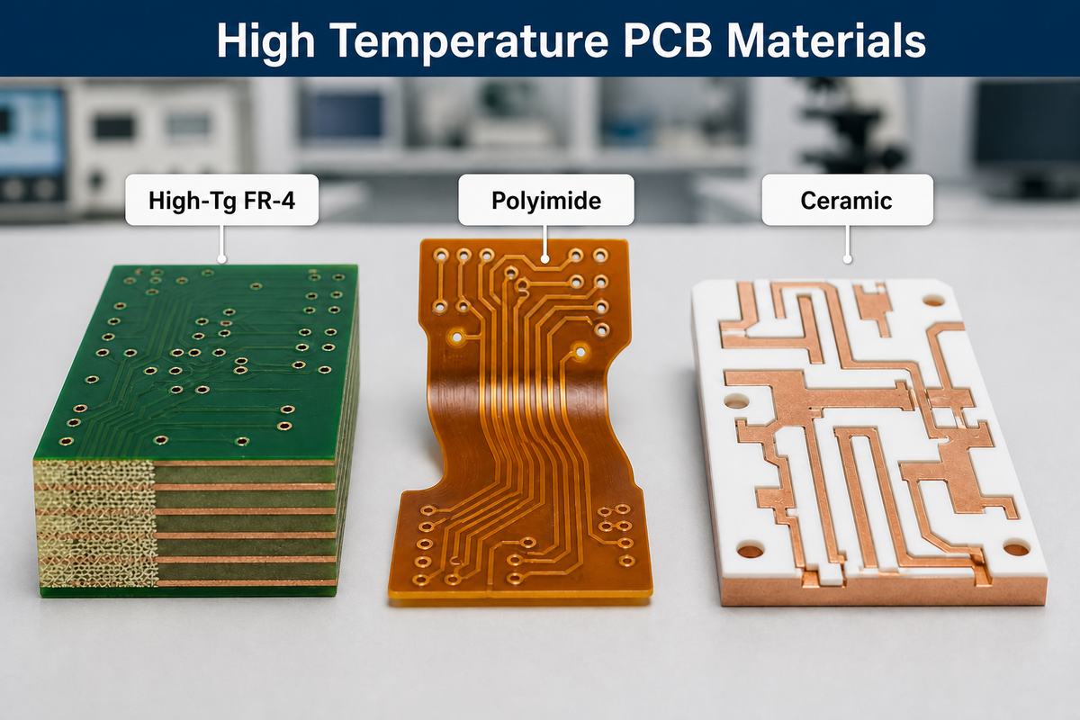
The main high temperature pcb materials solve different problems. Some resist resin softening, some conduct heat efficiently, and others preserve electrical behavior at high frequency.
| Material Family | Main Strength | Main Limitation | Typical Fit |
|---|---|---|---|
| High-Tg FR-4 | Familiar multilayer processing and improved thermal stability | Modest thermal conductivity | Industrial controls, automotive electronics, multilayer boards |
| Polyimide | High thermal endurance and flex compatibility | Moisture and process control require attention | Rigid-flex, aerospace, sensors, repeated thermal exposure |
| Ceramic | High-temperature stability, insulation, and heat transfer | Brittle and relatively costly | Power modules, LEDs, sensors, harsh environments |
| High-frequency laminate | Controlled Dk/Df and selected high-Tg options | Higher material and fabrication cost | RF, microwave, radar, high-speed links |
| Metal-core or thermal-spreading structure | Moves heat toward a chassis or heatsink | Limited routing freedom in common constructions | Power conversion and high-power lighting |
High-Tg FR-4 is usually the practical first candidate for a conventional rigid multilayer board. Polyimide becomes attractive when thermal endurance, flexibility, or repeated cycling dominates. Ceramic is justified when electrical isolation and heat transfer must be combined in a compact structure. RF materials should be chosen primarily from electrical loss and dielectric stability, then checked for thermal compatibility.
For a broader overview of laminate families, see our PCB material guide.
How Does High-Tg FR-4 Compare With Polyimide?
High-Tg FR-4 retains the established glass-fabric and epoxy-style production route used for many rigid multilayer PCBs. It offers a useful balance of cost, availability, drill behavior, lamination control, and lead-free assembly resistance. Our internal manufacturing source lists low-Tg FR-4 at 130–140°C, mid-Tg FR-4 at 150°C, and high-Tg FR-4 at 170–180°C; the exact laminate family still needs confirmation for each build.
Polyimide generally provides a higher thermal margin and is the standard foundation for flexible circuitry. It can also support rigid high-reliability constructions. However, resin chemistry, moisture handling, dimensional movement, bond system, and fabrication profile must all be controlled.
Choose between them using the application:
- Use high-Tg FR-4 when a rigid board needs stronger reflow and thermal-cycling performance without moving to a specialized material system.
- Consider polyimide when service temperature, repeated flexing, low outgassing requirements, or severe thermal cycling makes FR-4 unsuitable.
- Do not substitute one for the other without checking stackup thickness, copper balance, drilling, lamination, and assembly requirements.
When Is a High Temperature Polyimide PCB the Better Choice?
A high temperature polyimide pcb is often the better choice when the circuit must flex, fit a three-dimensional enclosure, or tolerate repeated thermal exposure. Common examples include engine-area sensors, aerospace instruments, downhole equipment, heaters, and compact rigid-flex assemblies.
Polyimide selection still requires several decisions:
- Adhesiveless or adhesive-based copper-clad laminate.
- Static-flex or dynamic-flex construction.
- Rolled-annealed or electrodeposited copper.
- Coverlay, bondply, stiffener, and rigid-area material compatibility.
- Moisture storage, baking, and assembly controls.
The bend area should not contain abrupt copper-width changes, unsupported vias, sharp corners, or an unsuitable grain direction. High thermal capability cannot compensate for a mechanically weak flex layout.
When Is a High Temperature Ceramic PCB Appropriate?
A high temperature ceramic pcb is appropriate when heat must move through an electrically insulating substrate while the circuit also needs low expansion and dimensional stability. Alumina and aluminum nitride are common choices, but their heat-transfer capability, strength, availability, metallization, and cost differ.
Ceramic is often considered for:
- Power modules and high-current semiconductor assemblies.
- High-power LEDs and laser drivers.
- Automotive, industrial, and energy sensors.
- RF modules requiring stable substrate properties.
- Circuits exposed to high temperature or aggressive environments.
Ceramic is not simply a premium replacement for FR-4. It is brittle, panelization and machining differ, and copper attachment or metallization becomes part of the thermal-mechanical design. The ceramic grade, thickness, copper system, mounting method, and heatsink interface should be assessed together.
How Should High Temperature PCB Design Address Heat and Expansion?
Good high temperature pcb design controls both temperature and mechanical strain. Material selection is only one part of that work.
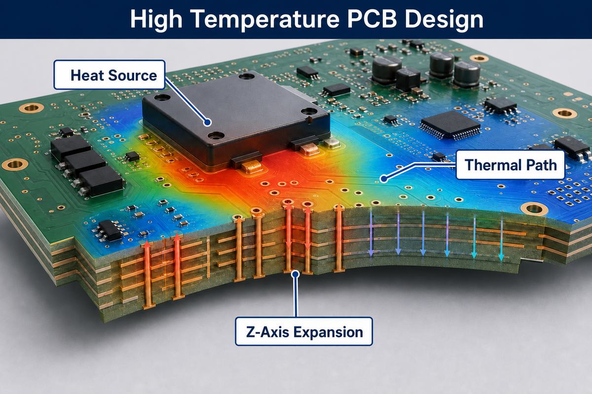
Use these design measures where the application requires them:
- Place heat-generating components to create a short, predictable path to copper planes, thermal vias, a chassis, or a heatsink.
- Use adequate copper area and balanced copper distribution to reduce local hot spots and warpage.
- Keep high-expansion laminate regions from overstressing dense via fields.
- Size plated holes and annular rings for the board thickness and thermal-cycle target.
- Avoid resin-starved regions around heavy copper and tightly packed features.
- Check component, solder alloy, connector, coating, and enclosure limits against the same temperature profile.
- Model or measure board temperature at the hottest operating condition rather than relying only on ambient temperature.
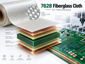
The PCB board stackup should be finalized with the fabricator. Glass style, resin content, copper weight, dielectric thickness, and material pairing affect both thermal movement and manufacturability.
How Do Fabrication and Assembly Affect Thermal Reliability?
Fabrication exposes a multilayer board to lamination heat, drilling, desmear, copper plating, solder-mask cure, surface finishing, and assembly. A material can have strong datasheet values and still fail if the process window is not matched to its chemistry.
Important controls include:
- Material storage and baking: Moisture can cause blistering, delamination, or conductive reliability problems during heating.
- Lamination profile: Heat-up rate, pressure, vacuum, cure time, and cooling influence resin flow and registration.
- Hole preparation: Drill parameters and desmear chemistry must create a clean surface for dependable copper plating.
- Copper plating: Adequate and uniform barrel copper is essential because plated holes carry Z-axis strain.
- Assembly profile: Peak temperature, time above liquidus, the number of reflow cycles, selective soldering, and rework all add thermal history.
- Handling after assembly: Cleaning, coating, mounting torque, and heatsink attachment can introduce additional stress.
Material equivalence should be approved from a property set, not a Tg value alone. If an alternate laminate is proposed, compare its datasheet, processing behavior, impedance model, and qualification requirements.
What Causes High-Temperature PCB Failures?
Most thermal failures are interactions between material, geometry, process, and operating conditions.
Common modes include:
- Barrel cracking: Z-axis expansion strains plated through holes during cycling.
- Pad lifting or copper separation: Heat and mechanical force weaken the copper-to-resin interface.
- Delamination or blistering: Moisture, insufficient cure, contamination, or excessive thermal exposure separates layers.
- Warpage: Unbalanced copper, asymmetric stackups, large temperature gradients, or incompatible materials distort the board.
- Insulation degradation: Heat, voltage, moisture, and contamination reduce electrical isolation.
- Solder-joint fatigue: Different expansion rates between the PCB, package, and solder repeatedly strain the joint.
- Local overheating: Poor heat spreading raises component and laminate temperature even when ambient conditions appear acceptable.
A useful stop condition is any operating point where the measured board temperature, deformation, insulation resistance, or interconnect performance leaves the validated range. At that point, the design needs a different material, improved cooling, a revised stackup, or a lower electrical/thermal load.
How Should Materials Be Tested and Qualified?
Qualification should reproduce the stresses that matter to the product. A generic thermal test is rarely enough.
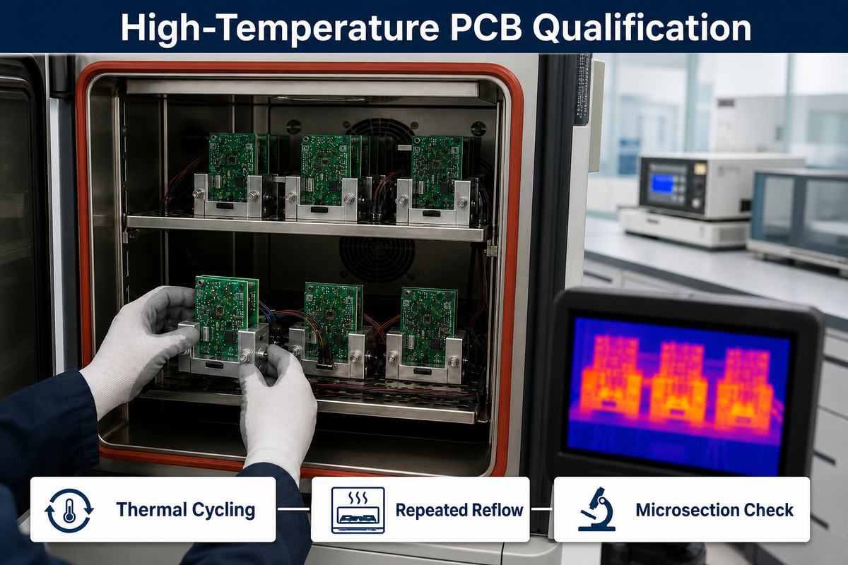
A practical plan may include:
- Incoming laminate certificate and lot traceability review.
- Tg, Td, T260/T288, CTE, moisture, Dk/Df, or thermal-conductivity data as applicable.
- Solder-float or repeated-reflow coupons for assembly exposure.
- Thermal cycling or thermal shock using the product’s temperature range and dwell conditions.
- Microsection analysis of plated holes, vias, copper interfaces, and dielectric condition.
- Insulation resistance, hipot, or leakage testing where voltage and safety require it.
- Dimensional, warpage, and registration checks before and after thermal exposure.
- Functional testing at temperature with the representative component load.
Pass/fail limits should be agreed before testing. Record the laminate manufacturer and grade, lot, stackup, coupon geometry, thermal profile, sample count, and inspection method so results remain traceable.
What Affects Cost and Lead Time?
Material price is only one cost driver. Total cost depends on whether the laminate is stocked, whether core and prepreg combinations are available, and whether the material needs special drilling, lamination, surface treatment, or handling.
The largest drivers are usually:
- Material family and exact grade.
- Finished thickness, layer count, and panel utilization.
- Copper weight and copper balance.
- Controlled impedance and dielectric tolerances.
- Sequential lamination, blind or buried vias, and via filling.
- Ceramic machining or specialized metallization.
- Qualification coupons, thermal testing, and documentation.
- Prototype quantity and production forecast.
Avoid specifying the most extreme material class by default. A high-Tg FR-4 solution may be more economical and easier to source than polyimide or ceramic when the measured environment remains within its validated range.
FAQ About High Temperature PCB Material
Is Tg the maximum operating temperature of a PCB?
No. Tg describes a resin transition region under a defined test method. Continuous operating temperature depends on the full laminate system, exposure time, mechanical load, voltage, components, solder joints, and product qualification.
Is a higher Tg always better?
No. It may improve thermal and dimensional stability, but it does not automatically improve thermal conductivity, signal loss, moisture behavior, or cost. Compare the complete property set.
Can standard FR-4 be used near a hot component?
Sometimes. The answer depends on the measured board temperature, duration, cycling, heat spreading, and reliability target. If the board approaches its validated limits, use improved cooling or a more suitable laminate.
Which material is best for repeated lead-free reflow?
Choose from Tg, Td, T260/T288, Z-axis CTE, moisture behavior, board thickness, via structure, and the number of assembly and rework cycles. High-Tg FR-4 is common, but the exact grade matters.
Does ceramic always run cooler than FR-4?
Not automatically. Ceramic can conduct heat much better, but final temperature also depends on copper, substrate thickness, contact area, thermal interfaces, airflow, and the heatsink or chassis.
What information is needed before choosing a material?
Provide operating and peak temperatures, dwell time, cycle count, voltage, frequency, power dissipation, board dimensions, stackup, copper weights, via structures, assembly profile, environment, test standard, and expected lifetime.
How Can EBest Circuit Support High-Temperature PCB Projects?
EBest Circuit supports material review, stackup planning, impedance requirements, prototype fabrication, PCB assembly, and production scaling for thermally demanding boards. Our available rigid-board material range includes low-, mid-, and high-Tg FR-4 as well as selected Isola, Nelco, Rogers, Taconic, PTFE, and other laminate families. Material availability, equivalence, and processing requirements are confirmed for the specific design.
Send your Gerber files, stackup, operating and peak temperatures, material preference, copper weight, quantity, assembly profile, and test requirements to sales@bestpcbs.com. We will review the thermal, electrical, mechanical, and manufacturing constraints and recommend a practical build route.