ESP32 C3 vs S3 is a comparison between a compact, cost-focused wireless controller and a more capable processor for demanding connected devices. The C3 suits many sensors, switches and simple control products, while the S3 offers more processing capacity, expanded memory options and interfaces for displays, cameras and USB applications. Both support 2.4 GHz Wi-Fi and Bluetooth Low Energy, so the biggest differences lie beyond basic wireless connectivity.
At EBest Circuit (Best Technology), we provide PCB fabrication, component sourcing and PCB assembly services for customers bringing electronic products into production. For an ESP32-based board, the selected chip or module affects the footprint, component list and assembly requirements. To discuss manufacturing your C3- or S3-based PCB assembly, contact sales@bestpcbs.com.
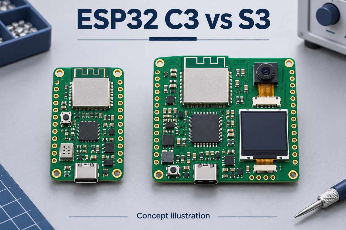
ESP32 Comparison Chart: C3 vs S3 Specifications
The ESP32-S3 has more computing and interface resources; the ESP32-C3 provides a simpler platform when those extras are unnecessary. The table compares chip specifications, rather than the features of a particular development board.
| Specification | ESP32-C3 | ESP32-S3 |
|---|---|---|
| Main CPU | Single-core, 32-bit RISC-V | Dual-core, 32-bit Xtensa LX7 |
| Maximum CPU clock | 160 MHz | 240 MHz |
| On-chip SRAM | 400 KB, including 16 KB used for cache | 512 KB |
| RTC SRAM | 8 KB | 16 KB |
| Wi-Fi | 2.4 GHz, IEEE 802.11b/g/n | 2.4 GHz, IEEE 802.11b/g/n |
| Bluetooth | Bluetooth 5 LE | Bluetooth 5 LE |
| USB controller functions | USB Serial/JTAG | USB Serial/JTAG and full-speed USB OTG |
| Chip-level GPIO count | 16 or 22, depending on variant | Up to 45 |
| Chip package | QFN32, 5 × 5 mm | QFN56, 7 × 7 mm |
| Flash and additional RAM | Flash configuration depends on part; no S3-style mapped PSRAM expansion | Flash and PSRAM configuration depends on chip/module variant |
Two distinctions matter when applying these figures to a board.
- GPIO count is not the number of free application pins. Memory connections, reserved pins and board peripherals reduce the usable signals.
- Chip size is not module size. The QFN dimensions exclude the module substrate, antenna and surrounding components.
ESP32-C3 vs ESP32-S3: CPU Performance and Maximum Speeds
The S3’s main advantage is more capacity for simultaneous work and demanding calculations. The C3 remains suitable for simpler workloads, such as reading sensors and periodically transmitting results.
Three aspects explain the performance difference.
- Concurrent tasks. The S3’s two cores can share suitable workloads, such as interface updates and application processing. A single sequential task does not automatically run twice as fast; the benefit depends on how the firmware distributes work.
- Numerical processing. The S3’s single-precision floating-point unit and SIMD instructions can help optimized signal-processing and selected machine-learning code. The software must use those resources, and the application must still fit its memory budget.
- Time spent waiting. A task waiting on a sensor, memory transfer or network response may gain little from a higher CPU clock. Its slowest operation can remain the limiting factor.
A graphical interface processing audio while maintaining a network connection is therefore a stronger reason to use the S3 than a simple increase from 160 MHz to 240 MHz. CPU speed also does not establish wireless throughput; neither chip becomes a 5 GHz or Wi-Fi 6 device because its processor runs faster.
How Much Storage Does ESP32 Have? C3 vs S3 Memory Compared
The C3 has 400 KB of on-chip SRAM, while the S3 has 512 KB; flash and PSRAM capacities depend on the specific part. An advertised “8 MB” or “16 MB” figure needs a memory type beside it to be meaningful.
- Flash holds firmware and persistent data. More flash can accommodate larger applications, graphics assets or files. Separate over-the-air update slots also need space alongside the running image and other partitions.
- SRAM holds active working data. Stacks, variables and buffers use this memory while the application runs. A larger flash device does not fix a shortage of working RAM.
- PSRAM adds working-memory capacity on supported S3 configurations. It is useful for larger image, display and audio buffers. Not every S3 module includes it, so the complete ordering code determines whether it is present.
For example, a camera application may fit its firmware in flash but still lack room for image buffers. A PSRAM-equipped S3 can address that capacity problem. External PSRAM uses an external interface and cache, however, so it does not behave like equally fast internal SRAM for every operation.
ESP32-C3 vs ESP32-S3: USB, GPIO and Peripheral Differences
The S3 offers more options for USB applications, displays and cameras. The C3 covers many simpler sensor and control interfaces, including SPI and I2C peripherals.
USB functions
- C3 USB Serial/JTAG supports programming, console communication and debugging. Its fixed-function controller cannot be reprogrammed into a general-purpose USB keyboard or storage device.
- S3 USB OTG supports device or host applications with suitable firmware and board hardware. It is full-speed USB, with 12 Mbit/s signaling, rather than 480 Mbit/s high-speed USB. Host operation also needs the appropriate power arrangement for the attached device.
Displays, cameras and available pins
- S3 LCD and camera interfaces support products that need these dedicated connections alongside buttons and other peripherals.
- C3 SPI or I2C connections can serve sensors and modest displays; a simple user interface does not automatically require an S3.
- Module pin assignments determine which signals remain available. Flash or PSRAM connections occupy pins, and boot-strapping pins need appropriate conditions during startup.
The interface list is therefore only the starting point. The selected module’s pin map determines which functions can coexist on the finished board.
ESP32-C3 vs S3 Deep Sleep Current: Chip vs Board Power Consumption
The C3 has a lower listed baseline deep-sleep current, but that figure alone does not predict finished-product battery life. The retained functions and the rest of the board also consume power.
| Device and state | Typical chip current | Conditions represented |
|---|---|---|
| ESP32-C3, deep sleep | 5 µA | RTC timer and RTC memory retained |
| ESP32-S3, deep sleep | 7 µA | RTC memory powered; RTC peripherals powered down |
| ESP32-S3, deep sleep | 8 µA | RTC memory and RTC peripherals powered |
These are typical chip values under the stated configurations, not maximum limits or measured currents for complete boards.
Three parts of the operating cycle determine the result.
- Sleep current from the complete board. Regulators, LEDs, memory, sensors and USB bridges may remain powered. One peripheral can outweigh the small difference between the two chips’ baseline figures.
- Energy used during each wake-up. Startup, wireless connection and transmission all contribute. A product that reconnects frequently can spend a substantial part of its energy budget outside sleep.
- Time spent active. Finishing a task sooner can sometimes offset a higher active current. This depends on the application and needs measurement.
Illustrative average-current calculation
Assume a board draws 100 mA for 1 second and 0.1 mA for the following 59 seconds.
Average current = (100 × 1 + 0.1 × 59) ÷ 60 ≈ 1.77 mA
These assumed currents are not measurements of either chip. The example shows why a full operating-cycle measurement is more useful than applying the lowest sleep figure to the entire battery-life calculation.
ESP32 S3 vs C3: Which Features Are Worth the Extra Cost?
The S3 earns its place when its extra resources enable a required function or remove a bottleneck. For a simple connected sensor or relay controller, much of that capacity may remain unused.
Applications that can justify the S3
- Camera products need enough working memory for image buffers and a suitable interface for the camera. A PSRAM-equipped S3 configuration can be valuable here.
- Graphical interfaces benefit from memory for graphics and processing capacity for rendering while other tasks continue.
- USB device or host products need an appropriate controller. In a suitable implementation, the S3’s OTG capability may avoid a separate USB controller.
Applications where the C3 may be sufficient
- Sensors that wake periodically, collect a reading and transmit it.
- Switches and relay controllers with modest processing demands.
- Connected devices with a small display and limited buffering requirements.
Production cost also includes the surrounding hardware. A richer camera or display product may add memory, connectors and power circuitry, even when the processor integrates more functions.
Compare complete component lists delivering the same required functions. There is no fixed C3-to-S3 price gap across all module types, memory configurations, quantities and supply conditions. A bare C3 chip and a fully equipped S3 development board are not equivalent cost comparisons.
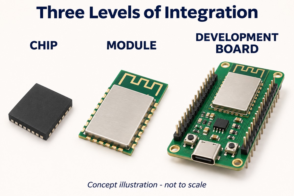
ESP32 Form Factors: C3 vs S3 Chips, Modules and Development Boards
The three forms differ in how much supporting circuitry they integrate. That changes the space occupied by the complete solution and the work remaining on the host PCB.
- Bare chip — the most integration work remains on the PCB. The surrounding circuit supplies the required power, clock, memory and RF implementation for the selected variant. It offers placement flexibility, but a small QFN package does not mean the complete circuit occupies only that area.
- Wireless module — more of the circuit comes in a defined footprint. Depending on the model, it integrates memory and an onboard antenna or external antenna connection. The host board still needs suitable power and the specified antenna clearance.
- Development board — additional hardware supports evaluation. Connectors, headers, regulators and programming circuitry make firmware and peripheral testing convenient. They also add size and power consumption that may be unnecessary in a custom product.
For enclosure planning, the antenna keepout is part of the installation space even where it contains no components. Nearby copper, metal hardware or batteries can affect the onboard antenna, so the module outline alone does not describe all the space it needs.
ESP32 Module Selection for PCB Assembly
The complete module part number connects the component list to the actual assembly requirements. Modules with similar names or appearances can differ in memory, antenna connection, pin usage and land pattern. A substitution can affect both the physical build and firmware behavior.
The manufacturing implications fall into three areas.
- Solder attachment. The land pattern and stencil apertures control where solder paste reaches the module pads. An underside ground pad, where present, also has soldering requirements that must be reflected in the assembly process.
- Module handling and reflow. Storage, moisture handling and the reflow profile follow the selected module’s requirements. A physically compatible replacement does not automatically carry identical processing requirements.
- Programming and test access. A connection accessible on the prototype may be covered after a display, shield or enclosure is fitted. Accessible power, ground, reset and programming signals support fixture-based programming and testing at the appropriate assembly stage.
At EBest Circuit, our PCB fabrication, component sourcing and assembly services bring the selected module into the complete board build. Matching PCB data and the specified component list establish what is assembled; firmware-loading and functional-test requirements define what the completed board must demonstrate.
FAQs About ESP32 C3 vs S3
Can an ESP32-C3 replace an ESP32-S3 without changing the PCB?
Generally, no. The chip packages and pin assignments differ, and modules are not interchangeable simply because they belong to the ESP32 family. A replacement also needs compatible peripherals, memory and firmware.
Can the same firmware binary run on both chips?
No. The C3 uses RISC-V and the S3 uses Xtensa, so the firmware must be built for the correct target. Some application source code can be reused, but pin assignments, drivers and target-specific features still need adaptation.
Do ESP32-C3 and ESP32-S3 support Bluetooth Classic audio?
Neither supports Bluetooth Classic. A conventional Bluetooth A2DP speaker application cannot be implemented simply by selecting one of these chips for its Bluetooth LE capability.
Does an ESP32 S3 USB C port always provide USB OTG?
No. USB-C describes the connector. The board’s wiring, controller selection, power circuit and firmware determine whether the port supports native USB device or host operation.
Is ESP32-C6 a direct upgrade from both C3 and S3?
It is a different option rather than a universal replacement. Its Wi-Fi 6 and IEEE 802.15.4 capabilities address different connectivity needs, while the S3 remains relevant for applications needing its processing, memory and display or camera resources.
Can both chips be programmed with the Arduino IDE?
Yes. The Arduino-ESP32 platform supports both families. Selecting the correct board target is essential, and a library that assumes a particular processor, pin map or peripheral may need changes when moving between them.
For your ESP32 C3 vs S3 project, match the processor to the workload and the exact module to the finished board. Discuss PCB fabrication, component sourcing and assembly with EBest Circuit at sales@bestpcbs.com.