Diplexer vs duplexer comes down to the job the RF network performs: a diplexer combines or separates two frequency bands at a common port, while a duplexer separates a transmitter and receiver sharing an antenna. A common filter-based duplexer uses different transmit and receive frequencies, not the same frequency. Both devices can be passive, and their circuit structures can overlap. Choose by the operating bands, insertion loss, isolation and power requirements—not by the product name alone. On a PCB, grounding, matching and coupling between traces also determine whether the selected device delivers its specified performance.
Key Takeaways
- Diplexer vs duplexer is primarily a distinction between frequency-band routing and transmit/receive separation, not between passive and active components.
- A diplexer filter connects two frequency-selective branches to one common port; signals can travel in either direction through a suitable reciprocal network.
- Most familiar frequency-division duplex (FDD) filter duplexers use separate TX and RX bands. Sharing an antenna does not mean sharing one frequency.
- A shared-antenna repeater needs enough isolation to prevent transmitter leakage and noise from degrading reception.
- A splitter divides power over a shared frequency range; a diplexer routes different bands and does not inherently impose a 3 dB power split.
- Insertion loss, return loss, port-to-port isolation, power handling and operating temperature must be checked against the actual band plan.
- PCB trace coupling can bypass a filter. Verify the assembled RF path, not just the component datasheet.
What Is the Main Difference Between a Diplexer and a Duplexer?
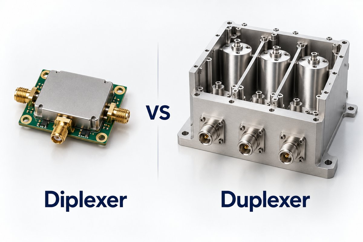
A diplexer separates signals by frequency band; a duplexer provides the transmit/receive separation needed by a shared-antenna radio. These descriptions identify different functions, so the terms are not always mutually exclusive.
| Feature | Diplexer | Filter-based duplexer |
| Main function | Combine or separate two frequency bands | Separate TX and RX paths at one antenna |
| Typical port labels | Common, low band, high band | Antenna, TX, RX |
| Frequency relationship | Two distinct passbands | Paired TX and RX bands in an FDD system |
| Selection priority | Passband coverage, loss and branch isolation | TX/RX isolation, loss and transmitter power |
| Example use | Two radio bands sharing a feedline | Cellular front end or shared-antenna repeater |
| Possible construction | LC, distributed, ceramic or other filter networks | SAW, BAW, cavity or other suitable filter networks |
TDK’s terminology guidance distinguishes band separation from transmission/reception separation. In practice, a frequency-selective network may serve both roles. Check the port diagram and specifications whenever a supplier uses the names differently.
At EBest Circuit, we support the PCB fabrication and assembly work around RF components. Our RF PCB manufacturing support connects the approved laminate, stackup and impedance requirements to the board that carries the filter network.
How Does a Diplexer Filter Route Two Frequency Bands?
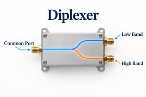
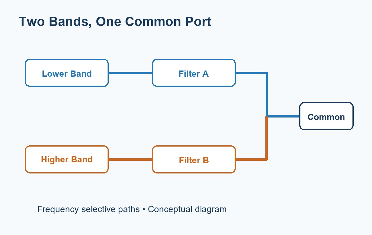
A diplexer filter sends each frequency band through its intended branch while rejecting that band at the other branch. The common port carries both bands together. Our diplexer guide explains the filter arrangement, circuit diagram and component specifications in more detail.
For example, Mini-Circuits’ DPGE-252-492R+ is specified for 2.4–2.5 GHz and 4.9–5.95 GHz. Those passbands illustrate band routing: the lower-band radio and higher-band radio connect to different branches, while a suitable shared antenna or feedline connects to the common port.
- Combining: each branch feeds its band toward the common port.
- Separating: the common-port signal is filtered into the two branches.
- Isolation: attenuation between branches limits unwanted interaction between the connected circuits.
The filter does not shift a signal to a different frequency. A 2.4 GHz input stays at 2.4 GHz; it is routed, not converted.
Does a Duplexer Use the Same Transmit and Receive Frequency?
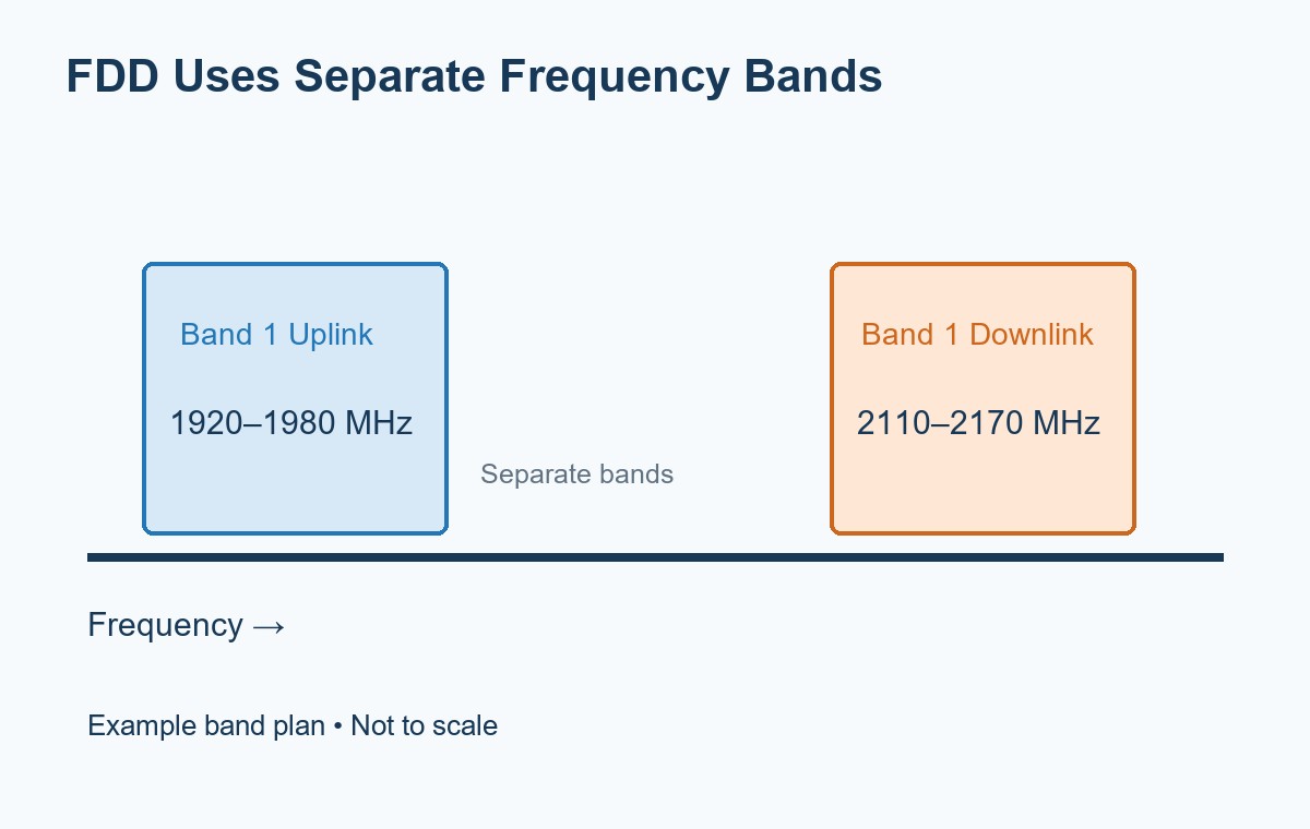
A conventional FDD filter duplexer uses different transmit and receive bands. It allows both paths to operate simultaneously through a shared antenna while filtering unwanted energy between them.
Qorvo’s TQQ7101 is a documented BAW duplexer example covering 1,920–1,980 MHz and 2,110–2,170 MHz in a 3 × 3 mm package. It is discontinued and is cited here only to show a real frequency plan—not as a recommendation for a new BOM. Uplink and downlink exchange TX/RX roles depending on whether the equipment is a handset or a base station.
Same-frequency simultaneous transmission and reception require a different isolation strategy, potentially including nonreciprocal routing and self-interference cancellation. A pair of ordinary band filters cannot distinguish two signals occupying the same frequency solely by which direction they travel.
Do You Need a Duplexer for a Repeater?
A repeater that transmits and receives simultaneously through one antenna normally needs a duplexer or another engineered isolation arrangement. Separate antennas can provide part of the isolation, but their separation alone does not guarantee acceptable receiver performance.
The receiver must detect a weak wanted signal while a nearby transmitter produces much greater RF power. Two checks matter:
- TX carrier rejection: keep the strong transmit signal from overloading the receiver front end.
- TX noise rejection in the receive band: keep transmitter noise from raising the receiver’s effective noise floor.
A broad VHF/UHF diplexer is therefore not an automatic substitute for a duplexer serving a closely spaced pair of repeater channels. Its passbands may route both repeater frequencies through the same branch.
How Much Isolation Does the RF System Need?
Required isolation comes from transmitter power and the receiver’s allowed interference level at the frequency being evaluated; there is no single correct isolation value for every diplexer or duplexer.
For a simple carrier-leakage estimate:
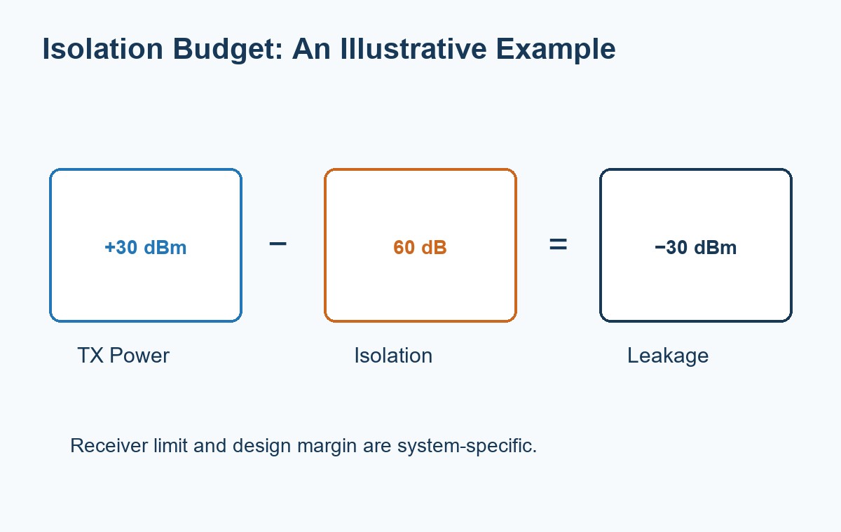
Required isolation (dB) = TX power (dBm) − allowed leakage at RX (dBm).
If a hypothetical transmitter produces +30 dBm and the chosen receiver limit at that interferer frequency is −30 dBm, the path needs at least 60 dB isolation before adding design margin. With only 40 dB isolation, the estimated leakage would be −10 dBm. These are calculation inputs, not universal receiver limits or EBest Circuit test results.
This estimate does not replace a receiver blocking or desensitization test. Transmitter noise inside the RX band, antenna mismatch and coupling around the filter require separate evaluation.
Which Specifications Should You Compare Before Selecting a Device?
Compare the complete passbands, loss, isolation, power rating and impedance first, then check the package and assembly requirements. Matching the advertised center frequency alone is insufficient.
| Parameter | Selection basis |
| Passband, MHz or GHz | Both occupied bands, including band edges and tolerances |
| Insertion loss, dB | TX output budget and RX sensitivity budget across each band |
| Isolation / rejection, dB | Specified port pair and frequency; check TX and RX bands separately |
| Return loss / VSWR | Matching at every relevant port under specified terminations |
| Power, W or dBm | Average and peak power, duty cycle, temperature and mismatch conditions |
| Reference impedance, Ω | 50 Ω or 75 Ω system compatibility as applicable |
| Package and mounting | Land pattern, grounding, reflow compatibility and mechanical envelope |
For scale, 1 dB of insertion loss passes about 79% of the incident power; 3 dB passes about 50%. Those ratios follow 10−loss/10. On a receiver, loss ahead of the first amplifier also consumes sensitivity margin.
If the system alternates TX and RX in time, evaluate its TDD switch and filtering architecture rather than assuming an FDD duplexer is needed. If several different bands must coexist, a diplexer or higher-order multiplexer may belong ahead of individual band-specific front ends.
What PCB Layout Issues Can Reduce Isolation?
Direct coupling between TX and RX traces, weak ground connections and mismatched launches can reduce assembled isolation even when the filter itself meets its datasheet.
- Separate the paths: avoid long parallel TX and RX runs that create a bypass route around the component.
- Maintain the reference plane: do not route RF traces across ground splits; keep return paths continuous.
- Follow the land pattern: reproduce the specified signal pads, ground pads and local grounding arrangement.
- Control transmission lines: calculate width and spacing from the actual stackup, dielectric properties and copper geometry.
- Review shielding: ground a shield enclosure properly rather than treating a metal lid as an automatic isolation improvement.
- Check assembly: inspect port orientation, bridges and ground-pad solder connections before troubleshooting the RF response.
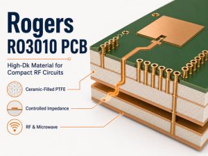
There is no universal “50 Ω trace width” suitable for every board. A width copied from a reference layout can be wrong when the dielectric thickness or material changes. During our manufacturing review, the approved stackup and fabrication data need to describe the same controlled-impedance structure.
How Should You Test the Assembled RF Paths?
Use calibrated RF measurements to verify insertion loss, return loss and isolation on the assembled network, then check receiver performance with the transmitter operating under the intended conditions.
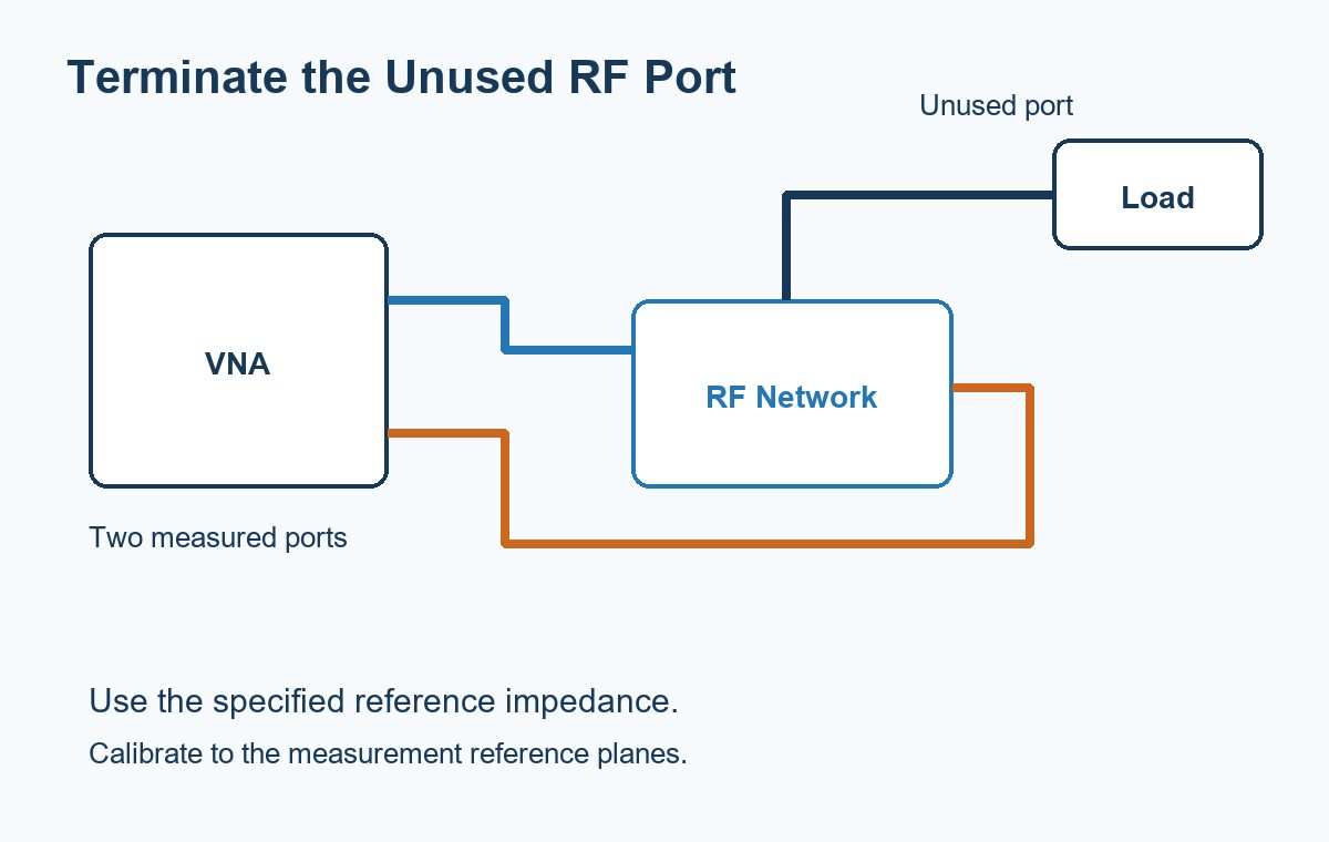
- Calibrate the vector network analyzer to the chosen reference planes and account for fixture or cable loss.
- Measure common-to-branch transmission across each passband.
- Measure branch-to-branch isolation across the required interference bands.
- Terminate unused ports in the specified impedance; an open port can change the network response.
- Verify powered-system behavior separately, including receiver desensitization and permitted TX power conditions.
For a three-port device, label the ports before interpreting S-parameters: S21 only means transmission from port 1 to port 2, not automatically “TX-to-antenna loss.” Also check instrument dynamic range; an apparent isolation floor may belong to the fixture or instrument.
For PCB assembly, define the inspection scope and any required RF acceptance procedure before production. Electrical continuity and visual solder inspection do not establish an RF isolation result.
FAQ About Diplexer vs Duplexer
What is the duplexer meaning in an RF circuit?
A duplexer connects a transmitter and receiver to a shared antenna while providing separation between their paths. The implementation depends on the radio architecture; a common FDD version uses two frequency-selective filters.
Diplexer vs splitter: can they do the same job?
Not usually. A splitter distributes signals over a common frequency range, while a diplexer routes different bands to different ports. An ideal equal two-way splitter divides power by 3 dB per output before excess loss; a diplexer does not inherently make that equal power division.
Duplexer vs circulator: what is different?
A filter duplexer separates TX and RX using frequency selectivity. A circulator is nonreciprocal and routes energy sequentially between ports. Antenna reflections and finite isolation still matter, so a circulator alone does not guarantee adequate receiver protection or same-frequency full-duplex performance.
Are diplexers and duplexers active components?
Many are passive networks and need no DC supply. An integrated RF module may also contain powered amplifiers or control circuits. Check the module schematic rather than classifying the whole assembly from the filter name.
Can you tune every diplexer or duplexer?
No. Some cavity assemblies have adjustable resonators, while many surface-mount ceramic, SAW and BAW devices have fixed responses. Tune only devices intended for adjustment, using the manufacturer’s procedure and suitable RF instruments.
Can two parts with the same package be interchanged?
No. The port assignment, frequency plan, matching, power rating and soldering requirements must also agree. A matching body size is not evidence of electrical or footprint compatibility.
How Can EBest Circuit Support Your RF PCB Assembly?
We support the board fabrication and assembly needed to turn an approved RF design into hardware. For diplexer or duplexer circuits, discuss the laminate and stackup, controlled-impedance requirements, component land patterns and assembly inspection scope with our team.
Send your RF PCB or PCBA project to sales@bestpcbs.com. Include the component part numbers and any RF acceptance criteria so we can review the manufacturing requirements alongside the board design.