An LCR meter measures the electrical behavior of resistors, capacitors, inductors, coils, and other passive components under an AC test signal. Unlike a basic multimeter, it can show not only resistance or capacitance, but also impedance, ESR, Q factor, dissipation, and phase-related parameters.
That matters because real components are not ideal. A capacitor has resistance and parasitic inductance. An inductor has winding resistance and stray capacitance. Their measured values can change with frequency, fixture setup, temperature, and even the surrounding PCB circuit.
This guide explains how an LCR meter works, how to choose the right measurement settings, and how to use it for component and PCB testing.
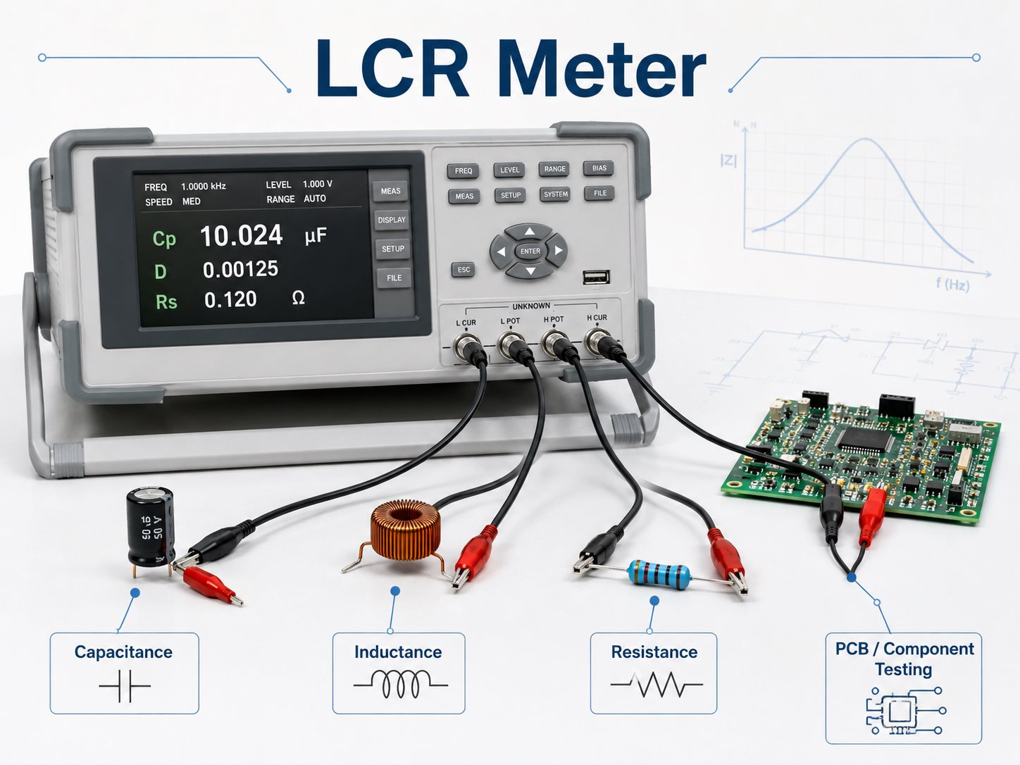
What Is an LCR Meter?
An LCR meter is an electronic instrument used to measure inductance (L), capacitance (C), and resistance (R).
The name comes from its three main parameters:
- L — Inductance, measured in henries (H)
- C — Capacitance, measured in farads (F)
- R — Resistance, measured in ohms (Ω)
A digital LCR meter normally measures these parameters by applying a controlled AC signal rather than relying only on DC measurement.
This makes it useful for checking components whose electrical behavior changes with frequency, including:
- ceramic and electrolytic capacitors;
- inductors and chokes;
- transformer windings;
- precision resistors;
- PCB coils and planar inductors.
For basic component identification, a simple handheld unit may be enough. More demanding laboratory or production measurements usually require tighter accuracy, controlled fixtures, and a wider test-frequency range.
What Does an LCR Meter Measure Besides L, C, and R?
L, C, and R are only the starting point. Many LCR meters also calculate secondary parameters that show how much loss or parasitic behavior a component has.
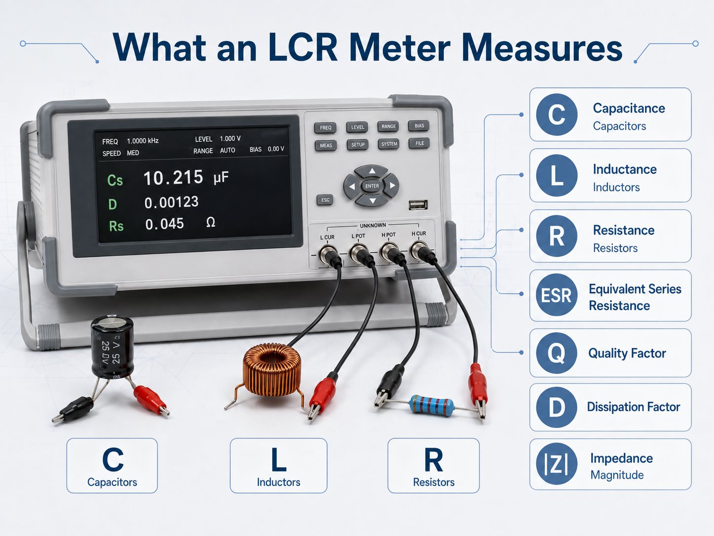
| Parameter | Meaning | Typical Use |
| L | Inductance | Inductors, coils |
| C | Capacitance | Capacitors |
| R | Resistance | Resistors, winding resistance |
| Z | Impedance | Overall AC behavior |
| ESR | Equivalent series resistance | Capacitor loss |
| Q | Quality factor | Inductor performance |
| D | Dissipation factor | Capacitor loss |
| θ | Phase angle | Reactive behavior |
For example, two capacitors may both measure close to 100 µF, yet one may have much higher ESR. In a power circuit, that difference can affect ripple, heating, and stability even though the capacitance reading looks acceptable.
Q factor is commonly used for inductors. It compares reactive behavior with resistive loss at a specified frequency. Dissipation factor performs a similar role for capacitors.
Because these values are frequency-dependent, an ESR or Q reading is much more useful when the test frequency is also recorded.
How Does an LCR Meter Work?
An LCR meter applies a known AC signal to the device under test and measures how the component responds.
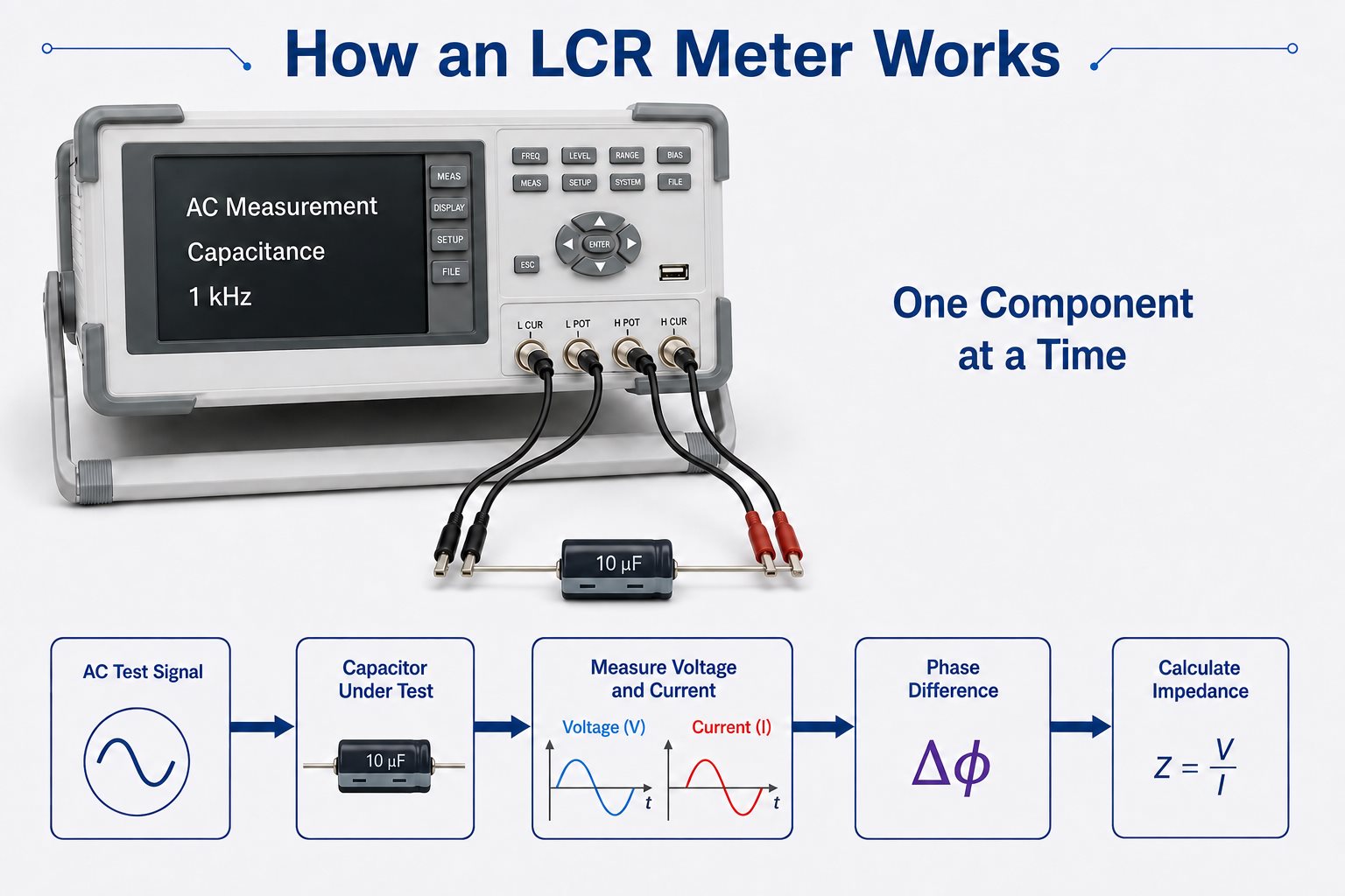
The measurement sequence is roughly:
- Generate an AC test signal.
- Apply it to the component.
- Measure voltage and current.
- Determine the phase difference between them.
- Calculate complex impedance.
- Convert the result into L, C, R, ESR, Q, D, or another selected parameter.
The AC signal is important because capacitors and inductors respond differently as frequency changes.
For a capacitor: Xc = 1 / (2πfC)
For an inductor: XL = 2πfL
As frequency rises, capacitive reactance falls while inductive reactance rises.
A more precise benchtop LCR meter may also use automatic balancing bridge techniques and four-terminal-pair connections. These methods reduce errors caused by test leads, contact resistance, and fixture parasitics.
Why Does Test Frequency Matter in LCR Measurements?
The same component can produce different LCR readings at different frequencies.
This is normal. Real components contain parasitic elements that become more or less significant as frequency changes.
Typical examples include:
- Large electrolytic capacitors are often characterized at relatively low frequencies.
- Small ceramic capacitors may be measured at 1 kHz or higher, depending on the specification.
- Power inductors are commonly tested differently from small RF inductors.
- An RF inductor can change behavior significantly as the test frequency approaches self-resonance.
A capacitor, for example, does not consist of capacitance alone. Its equivalent circuit also includes ESR and parasitic inductance. At low and moderate frequencies, capacitance may dominate. At sufficiently high frequencies, parasitic inductance becomes much more important.
For component acceptance testing, the best practice is simple:
Use the measurement frequency stated in the component datasheet or applicable test specification.
If the test is for troubleshooting rather than formal verification, choose a frequency relevant to the application and keep it consistent when comparing suspect and known-good components.
What Is the Difference Between Series and Parallel Measurement Modes?
Series and parallel modes are equivalent circuit models used to represent the losses in a real component.
Common settings include:
- Cs — series capacitance
- Cp — parallel capacitance
- Ls — series inductance
- Lp — parallel inductance
- Rs — series resistance
- Rp — parallel resistance
They do not mean that the physical component changes internally. The meter is simply expressing the same impedance using a different mathematical model.
As a practical rule:
- Lower-impedance devices are often represented with a series model.
- Higher-impedance devices are often represented with a parallel model.
The correct setting depends on the device, frequency, and test specification.
This becomes important when checking lossy capacitors or inductors. Cs and Cp, or Ls and Lp, may not give identical numerical results. If a datasheet specifies one equivalent model, use that same model during verification.
Handheld vs Benchtop LCR Meter: What Is the Difference?
The main difference is not simply portability. It is the amount of control the instrument gives over the measurement.
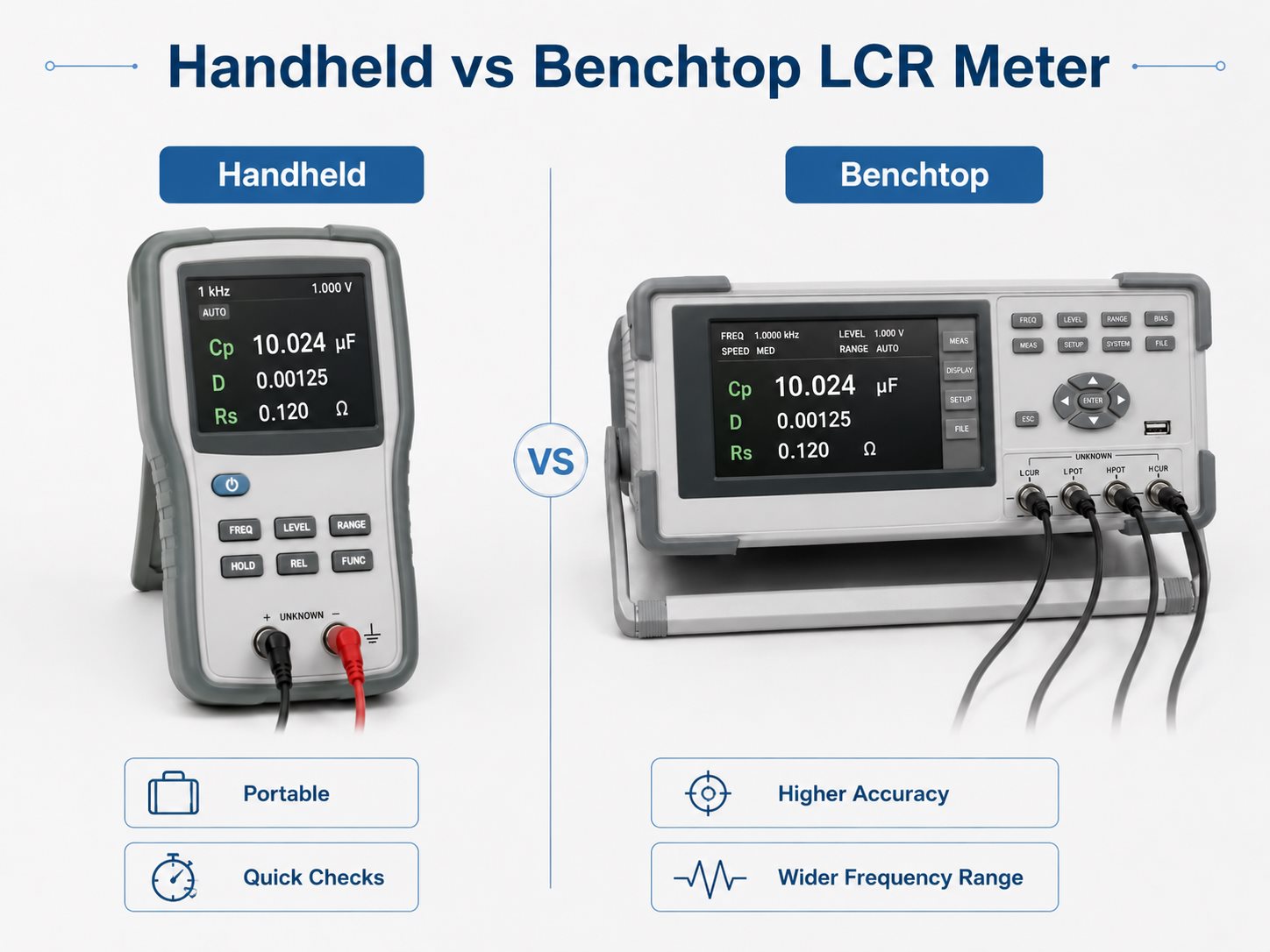
| Feature | Handheld LCR Meter | Benchtop LCR Meter |
| Portability | High | Low |
| Frequency range | Usually narrower | Usually wider |
| Accuracy | General-purpose | Higher precision |
| Fixtures | Basic | More options |
| Bias capability | Limited | More common |
| Automation | Limited | Often supported |
| Typical use | Repair, field work | R&D, QC, production |
A handheld LCR meter is useful for:
- maintenance;
- component sorting;
- quick incoming checks;
- general troubleshooting.
A benchtop unit is more appropriate when a test requires:
- tighter tolerances;
- repeatable fixtures;
- multiple test frequencies;
- DC bias;
- automated data collection;
- production pass/fail limits.
The right choice depends on what needs to be measured, not on whether one instrument has more features.
LCR Meter vs Multimeter: What Is the Difference?
A multimeter is designed for general electrical troubleshooting. An LCR meter is designed to characterize passive components under controlled AC conditions.
A typical multimeter measures:
- AC/DC voltage;
- current;
- resistance;
- continuity;
- diode behavior.
Some models also provide basic capacitance or frequency functions.
An LCR meter can usually measure:
- inductance;
- capacitance;
- resistance;
- impedance;
- ESR;
- Q factor;
- dissipation factor;
- phase angle.
It also allows the user to select test frequency and, on many models, the equivalent circuit.
For checking whether a 1 kΩ resistor is open, a multimeter is sufficient.
For determining whether an inductor still meets its inductance and Q requirements, or whether a capacitor has excessive ESR, an LCR meter gives much more useful information.
How to Use an LCR Meter?
A reliable LCR measurement depends on both the instrument settings and the test setup.
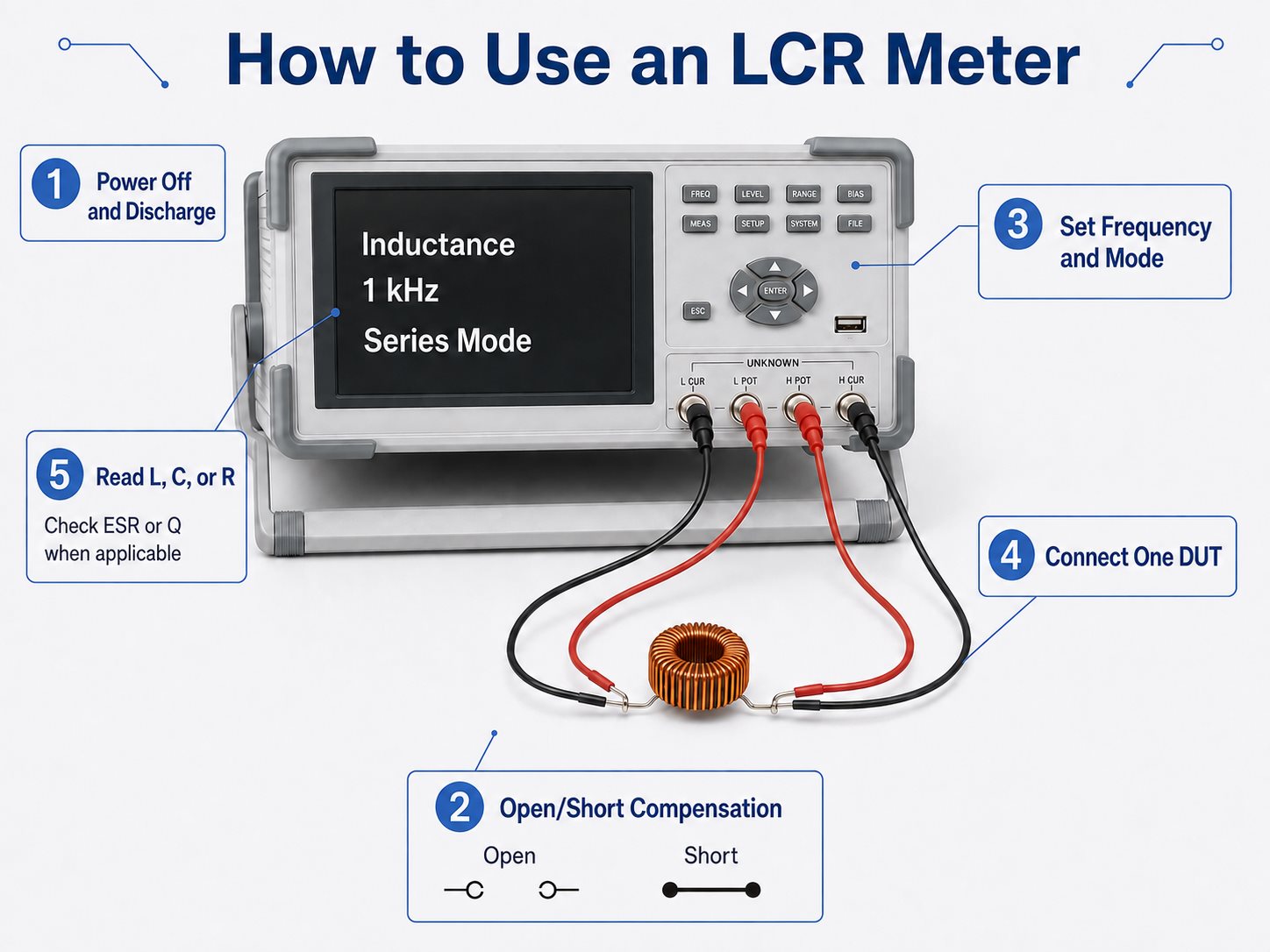
A practical workflow is:
- Power off the circuit. Passive LCR measurements should not normally be made on an energized circuit.
- Discharge capacitors. Stored charge can distort the reading or damage the meter input.
- Choose the correct fixture. SMD tweezers work well for small chip components. Kelvin clips or dedicated fixtures improve repeatability for low-impedance measurements.
- Perform open and short compensation. This reduces errors from leads, fixtures, stray capacitance, and residual impedance.
- Select the main parameter. Choose L, C, R, Z, or automatic detection if supported.
- Set the test frequency. Match the datasheet condition when verifying a rated value.
- Choose series or parallel mode. Use the mode specified for the component whenever possible.
- Connect the component securely. Poor contact can cause unstable or inflated readings.
- Read the secondary parameter as well. Capacitance plus ESR, or inductance plus Q, is often more informative than the primary value alone.
- Compare under the same conditions. Frequency, fixture, temperature, and circuit model should remain consistent between measurements.
For repeated inspection, document the meter settings in the test instruction. Otherwise two operators can test the same component and obtain different results simply because they used different frequencies or modes.
Can You Measure Components Directly on a PCB with an LCR Meter?
Yes, but an in-circuit reading may include the electrical effect of other components connected around the part.
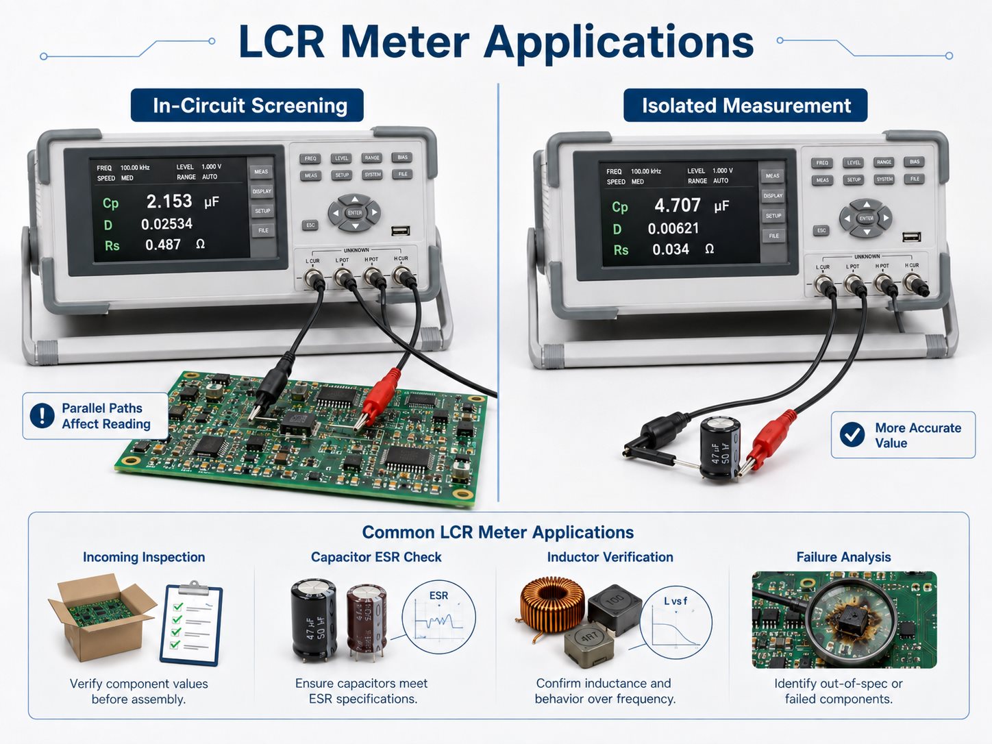
This is especially common with:
- capacitors connected in parallel on a power rail;
- resistors forming parallel current paths;
- transformer or inductor windings connected to other circuitry;
- semiconductor junctions;
- passive filter networks.
Suppose several capacitors share the same supply rail. Measuring one capacitor without removing it may effectively measure part of the entire network rather than that single component.
In-circuit LCR measurements are still useful for quick screening. A technician may compare a suspect PCB with a known-good board and look for a major difference.
For an accurate standalone value, it may be necessary to:
- lift one terminal;
- remove the component;
- isolate the surrounding circuit;
- test the part in a dedicated fixture.
A strange in-circuit reading should therefore be treated as a diagnostic clue, not immediate proof that the component has failed.
What Causes Incorrect LCR Meter Readings?
Many incorrect readings come from the setup rather than the component itself.
Common causes include:
- Wrong test frequency — the component is being measured under conditions different from its datasheet rating.
- Wrong equivalent model — Cs/Cp or Ls/Lp selection changes the reported value.
- No open/short compensation — lead and fixture parasitics become part of the result.
- Poor contact — oxidized leads or unstable clips add resistance.
- Long test leads — extra inductance and capacitance become significant.
- In-circuit paths — nearby components alter the measured impedance.
- Temperature change — many passive components have measurable temperature coefficients.
- DC bias effects — some ceramic capacitors lose effective capacitance under applied bias.
- Contamination — moisture, flux residue, or dirt can affect high-impedance and low-capacitance measurements.
- Operating near the meter limits — accuracy usually falls when the component value is close to the instrument’s practical measurement range.
Fixture parasitics deserve particular attention when measuring very small capacitance or inductance. A few picofarads of stray capacitance may be negligible when measuring microfarads, but very significant when the DUT itself is only a few picofarads.
Low-resistance and low-inductance measurements similarly benefit from Kelvin or four-wire techniques because ordinary test-lead resistance can become comparable to the device being measured.
How Are LCR Meters Used in PCB and PCBA Testing?
LCR meters are useful in PCB and PCBA work when a simple resistance or continuity check does not provide enough information.
Typical applications include:
- Incoming component inspection — verifying resistor, capacitor, and inductor values before assembly.
- Capacitor troubleshooting — checking capacitance, ESR, or dissipation in unstable power circuits.
- Inductor and coil verification — measuring inductance, winding resistance, and Q.
- Transformer checks — comparing winding parameters with approved samples.
- Alternative-part verification — confirming that a substitute passive component matches the required electrical behavior.
- First-article troubleshooting — checking suspect components against BOM or datasheet requirements.
- Failure analysis — identifying parameter drift after thermal or electrical stress.
- Printed coil testing — measuring PCB inductors, planar coils, and similar structures after fabrication.
The measurement procedure should define more than a nominal component value.
For production or quality inspection, useful test requirements normally include:
- test frequency;
- allowable tolerance;
- fixture type;
- series or parallel mode;
- secondary parameter limits where relevant.
For PCB coils, transformers, RF structures, and precision analog circuits, these conditions are especially important because parasitic behavior is part of the real electrical performance.
FAQs About LCR Meters
What does LCR stand for on a meter? LCR stands for inductance, capacitance, and resistance. These are the three primary passive-component parameters measured by the instrument.
Can an LCR meter measure ESR? Yes, many digital LCR meters can measure or calculate equivalent series resistance. ESR is commonly used when evaluating capacitor loss.
Why does capacitance change when I change the test frequency? Real capacitors contain ESR, dielectric losses, and parasitic inductance. Their combined impedance changes with frequency, so the calculated capacitance may also change.
Is an LCR meter better than a multimeter for testing capacitors? For detailed capacitor characterization, usually yes. An LCR meter can measure capacitance together with ESR, dissipation, and frequency-dependent behavior that a basic multimeter cannot show.
Can I test a capacitor without removing it from the PCB? You can perform an in-circuit screening test, but parallel components may influence the reading. Isolate or remove the capacitor when an accurate standalone value is required.
What frequency should I use on an LCR meter? Use the frequency specified in the component datasheet when checking compliance with a rated value. For troubleshooting, use a frequency appropriate to the application and keep it consistent between comparisons.
How Can EBest Circuit Support Your PCB and PCBA Project?
If you need PCB or PCBA manufacturing support involving passive-component verification, printed coils, electrical testing, or assembly troubleshooting, send your Gerber files, BOM, and test requirements to sales@bestpcbs.com.