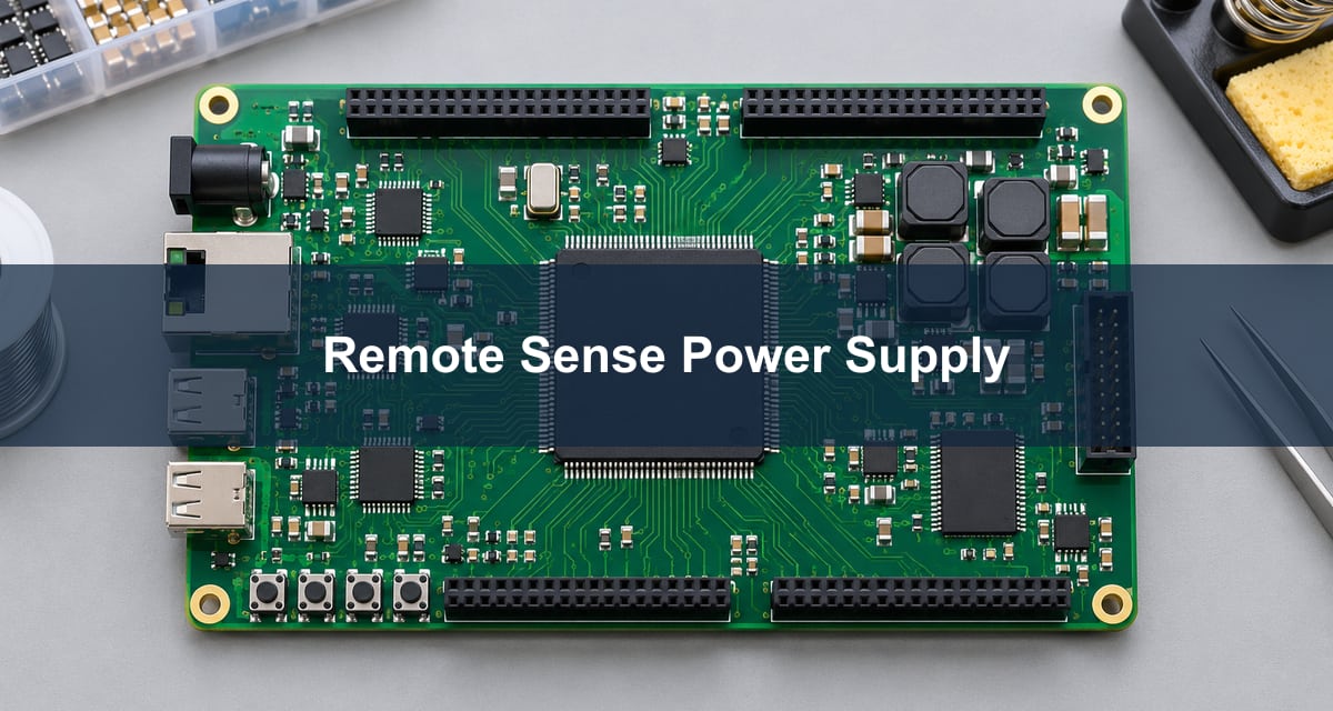
A remote sense power supply regulates the voltage at the point its feedback wires or PCB traces monitor, rather than only at the regulator output. Use remote sensing when the measured steady voltage drop to a critical load consumes its voltage budget and the regulator explicitly supports the connection. If the rail is only out of tolerance during fast load changes, first investigate the transient response instead of moving the feedback point.
Consider an FPGA board with a nominal 1.000 V core rail. The regulator output looks correct on the meter, but the voltage at the FPGA drops at high load. The decision is whether to move the sensing point, improve the copper path, or put regulation closer to the load. The example values below are hypothetical; use the actual device limits for acceptance.
Remote Sense Power Supply: What Voltage Is Controlled?
The feedback loop controls the difference between its designated sense points. In local sensing, those points are near the regulator output and return. In remote sensing, they represent the load supply and its return. The power path still carries load current; the separate feedback connections tell the regulator what voltage reaches the load.
Mark two node pairs on the schematic: regulator output and its nearby return, then load supply and its nearby return. Measure each pair at steady load. Measuring the load supply against regulator ground mixes two locations and can hide the voltage lost in the ground path. Texas Instruments’ PMIC remote-sense guide shows how the sensed voltage relates to the board connection.
PCB Trace Voltage Drop: Count the Supply and Return
In this teaching example, 6 A through 4 mΩ of supply copper and 2 mΩ of return copper produces a 36 mV round-trip DC drop. With 1.000 V at the source, the load sees about 0.964 V. If the design has allocated only 20 mV to distribution loss, local sensing alone misses that allowance by 16 mV.
| Illustrative input | Value and consequence |
| Supply path | 4 mΩ × 6 A = 24 mV drop |
| Return path | 2 mΩ × 6 A = 12 mV drop |
| Combined path | 6 mΩ; 36 mV drop and 216 mW of distribution loss at 6 A |
| Maximum path resistance for a 20 mV allowance | 20 mV ÷ 6 A = 3.33 mΩ, before other margins |
Use resistance at the relevant operating temperature, including vias, neck-downs and connectors in the current path. Remote sense can compensate voltage at one node pair, but it cannot remove the 216 mW dissipated in the example copper path. If heating or connector loss is already unacceptable, fix the path even if the regulator can compensate the voltage.
Remote Sense vs Local Sense: Choose the Feedback Point
Prefer local sensing if the load stays within budget across the operating range. Use supported remote sensing for a critical point when distribution drop is the limiting error. If multiple loads need tight regulation or the power path overheats, reduce its resistance or regulate closer to the load rather than raising the source voltage indefinitely.
| Option | When to choose it and what to check |
| Local sense | Use if path loss fits the budget. Check DC and transient limits at the load. |
| Differential remote sense | Use for tighter DC accuracy at one point. Check source headroom, sense input limits, and other loads. |
| Better copper or local regulation | Use if heat, multiple loads or limited correction rule out remote sense. Check space, current and transient behavior. |
In the example, local sense could meet the DC allowance if the path is reduced below 3.33 mΩ with sufficient margin. Remote sense could instead raise the source to roughly 1.036 V at 6 A to deliver 1.000 V to the FPGA, but that value is only an ideal steady-state estimate. An upstream branch on the same rail might then see close to the higher source voltage.
Differential Remote Sensing: Land Both Connections at the Load
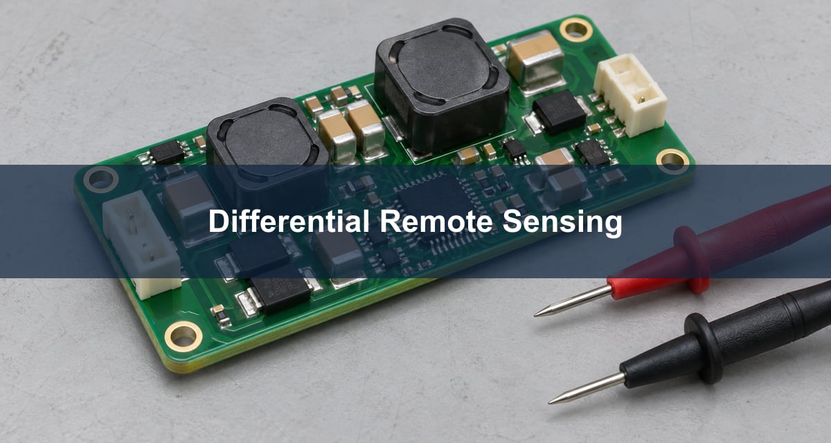
Take the positive sense point from the intended load supply location and the negative sense point from its corresponding return. If the device exposes dedicated package sense pins, follow the device and regulator instructions for using them. A connection at a distant ground via can leave part of the return-path drop outside the loop.
The TPS7H4011 datasheet, section 9.3.3, illustrates a differential connection for an FPGA and accounts separately for resistance in the power and ground paths. This is an architecture example, not a recommendation to copy the pin connections onto another controller. Confirm which input connects directly to the load, which uses a divider, and where that divider returns.
Buck Converter Layout Guidelines for Sense Traces
Route the differential sense traces together through a quiet part of the board. Keep them away from the switch node, inductor and high-current switching loops, and follow the device’s feedback-component placement guidance. The sense traces are feedback inputs, not a controlled-impedance data link; adding a differential impedance constraint is not the main design task.
Mark the sense pickoffs separately from the force copper in the schematic and layout. Where practical, include accessible measurement points at the source and load, but do not add long stubs to the feedback pins just to probe them. At review, follow both paths on the actual board artwork, including layer transitions and shared reference copper.
Remote Sensing Compensation: Check Headroom and Fault Behavior
Check how much additional output voltage the exact regulator or supply can provide while meeting its limits. The source may reach a duty-cycle or output limit before the load voltage is restored. Check the feedback input range, maximum correction, overvoltage behavior, startup sequence, and any limits imposed by the source-side capacitors or nearby loads.
A removable connector makes the feedback path a fault concern as well as a routing concern. Determine from the device documentation what happens if either sense path opens, is reversed, or is present before the power path. Do not assume the controller falls back to local sense. For prototypes, verify the documented behavior with a controlled setup that protects the actual load; do not unplug feedback from a live production board to find out.
Buck Converter Feedback Loop Design With Remote Sense
Moving the sensing point can include more interconnect and load-side capacitance in the regulated path. The response then depends on the controller, board parasitics, local and remote output capacitors, and the specific compensation scheme. Do not add a filter or copy a capacitor value from another regulator unless the manufacturer supports the arrangement.
Check the permitted output capacitance and layout, then evaluate the loop by the manufacturer’s recommended method. A stable response with an electronic load at the regulator terminals does not prove stable regulation with the production load at the far end. For the FPGA example, keep the load-side decoupling and the real power/return connection in the validation setup.
Load Transient Response: Measure Both Ends Before Release
Measure the source and load node pairs under the same repeatable current step. Record the starting and ending current, slew rate, probe setup and operating conditions. A DC correction that reaches 1.000 V after settling can still leave an initial dip below the FPGA’s limit or overshoot after a rapid load release.
First verify steady voltage at minimum and maximum load. Then check startup, step-up, step-down and recovery at the expected operating limits. Use representative load capacitance and compare both source and load readings to their own limits. If the load shows an early dip but steady voltage is correct, investigate local decoupling and interconnect inductance; if both ends ring after moving the feedback point, review loop stability. See Analog Devices’ transient-testing guidance and the PCB target impedance guide for the related dynamic budget.
Frequently Asked Questions
Can a bench supply’s remote sense validate my onboard regulator?
It can help regulate the external power at the chosen bench-supply sense point. It does not demonstrate that the onboard regulator’s own feedback loop or local load transient response will pass.
Can I use one sense lead and the existing ground copper?
Only if the regulator supports that sensing topology and the return error is acceptable. A single-ended measurement does not automatically cancel voltage differences across current-carrying ground copper.
Can remote sense reduce heating in a PCB connector?
No. It can compensate voltage drop at the selected load while the connector still dissipates power. Evaluate connector current and temperature on their own.
Should I simply raise a locally sensed setpoint instead?
A fixed offset can correct the voltage at one load current but overcompensate at another. Compare the lowest and highest load voltages and check all branches before adopting a fixed offset.
What if two devices share the rail but need different voltage margins?
One feedback pair directly regulates one location. Measure both loads under their actual current combinations. Consider reducing path resistance or splitting the rail if the required voltage windows cannot both be maintained.
Will measuring against chassis ground give the right load voltage?
Not necessarily. Measure between the load’s supply and its intended local return using a suitable setup; chassis ground can be a different electrical point. Do not short an isolated or offset return with a grounded instrument lead.
Can I run the sense pair through a detachable connector?
Use the connector only when the regulator and system design account for contact sequencing, continuity faults and the resulting output behavior. A voltage pass with the connector fully seated is not a fault test.
What is the quickest way to tell DC loss from a fast transient?
Compare the two node pairs at settled loads, then record the same pairs across a current step. A difference that persists at steady current is distinct from a brief dip or ringing that recovers.
Prepare the Power Path for Fabrication Review
For a Best Technology fabrication review, send the board revision, stackup, current path and sense-point locations, copper requirements and any required test structures to sales@bestpcbs.com. Keep the regulator limits and load-side acceptance criteria with the electrical validation plan; a fabrication review does not qualify the regulator loop.