PCB manufacturing PCB manufacturing
Home > Blog

counterbore vs countersink

Counterbore vs Countersink: Differences, Symbols & Sizes
Thursday, August 13th, 2026

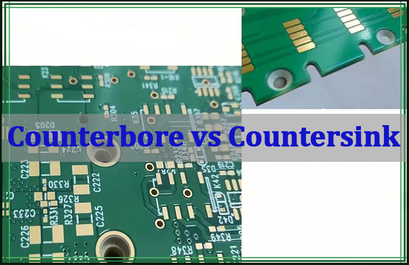
The practical counterbore vs countersink difference is the shape of the recess and the screw head it supports. A counterbore is cylindrical with a flat floor for a socket-head or similar fastener. A countersink is conical and normally receives a flat-head screw. On a PCB, the decision also depends on board thickness, copper clearance, mounting load, enclosure fit, and whether the fabrication drawing defines the feature clearly.

Select the fastener and mechanical stack-up before selecting the recess. Then define the finished hole, recess geometry, machined side, depth or angle, tolerances, and inspection method. This order prevents a drawing that looks correct from producing a proud screw head, exposed copper, insufficient laminate, or an inaccessible driver.
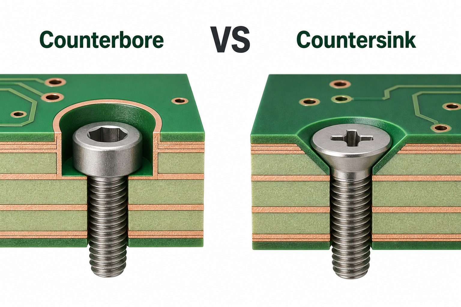
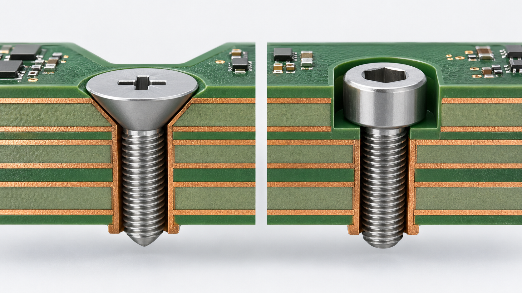
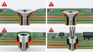
3D comparison of counterbore and countersink holes with matching screws in a multilayer PCB

What Is the Difference Between a Counterbore and a Countersink?

A counterbore has straight walls and a flat bearing floor, while a countersink has an angled wall that follows a flat-head screw. Both can reduce hardware height, but their geometry, load contact, cutting tools, drawing callouts, and inspection requirements are different.

Comparison Counterbore Countersink
Recess shape Cylindrical, straight wall, flat floor Conical, angled wall
Typical fastener Socket-head cap screw or another head with a flat bearing face Flat-head screw with a matching included angle
Drawing controls Hole diameter, recess diameter, depth, side, and tolerance Hole diameter, recess diameter or depth, angle, side, and tolerance
Main PCB risk Too little laminate below the pocket Excessive laminate removal or copper exposure around the cone

The choice is functional rather than cosmetic. A counterbore provides a flat seat and controlled recessed height. A countersink can place a compatible flat-head screw flush with the board surface. If the screw can remain above the PCB, a normal clearance hole and standoff usually remove less laminate and require less inspection.

When to Use Counterbore vs Countersink?

Use a counterbore when the fastener has a cylindrical head that needs a flat recessed seat; use a countersink when a matching flat-head screw must sit flush or below the surface. Use neither feature when a standard clearance hole, standoff, washer, bracket, or recessed enclosure boss can meet the same mechanical requirement.

What is a counterbore used for?

A counterbore is used to recess a socket-head cap screw, washer, nut, or other hardware that needs a flat bearing floor. In a PCB assembly, it may reduce overall hardware height, clear an enclosure surface, or control the screw-head position. The pocket still needs enough diameter for the head and driver, and enough remaining board thickness to carry the clamping load.

When is a countersink the better choice?

A countersink is the better choice when the selected flat-head screw must be flush and its underside angle can be matched by the machined cone. Do not choose it only because it looks streamlined. The taper can remove substantial laminate from a thin PCB and may enlarge the required copper keep-out well beyond the drilled hole.

  • Choose by the actual fastener drawing, not by thread size alone.
  • Confirm whether the board is supported by a standoff or spans an unsupported area.
  • Check driver, washer, component, and enclosure clearances.
  • Prefer a standard hole when recessing does not solve a defined packaging or load problem.

Counterbore vs Countersink Hole Geometry

A counterbore vs countersink hole starts with a finished mounting-hole diameter, commonly identified as D1, plus a larger recess diameter, commonly identified as D2. A counterbore then needs a pocket depth. A countersink needs an included angle and either a maximum diameter or controlled depth.

  • Counterbore: define D1, D2, pocket depth, machined side, and any edge-break requirement.
  • Countersink: define D1, D2 or depth, included angle, machined side, and final screw position.
  • Both: define quantity, XY location or hole identifier, tolerance, plated or non-plated condition, and drawing datum.

The recess is not simply a larger drilled hole. Its complete three-dimensional shape affects the screw contact, remaining laminate, surface copper, solder mask, internal copper, and the inspection method. Check the full D2 contour on every affected layer rather than applying clearance only around D1.

Counterbore vs Countersink Symbols

Counterbore vs countersink symbols identify the feature type, but they do not replace the dimensions. The conventional counterbore symbol is ⌴, while the countersink symbol is ⌵. A production callout still needs the relevant diameters, depth or angle, quantity, tolerance, plating condition, and machined side.

A counterbore note normally communicates the through-hole diameter followed by the counterbore diameter and depth. A countersink note normally communicates the through-hole diameter followed by the countersink diameter and included angle. CAD systems may arrange callouts differently, so the fabricator should not have to infer the meaning from symbol order alone.
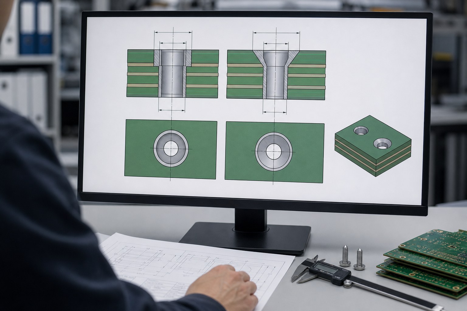
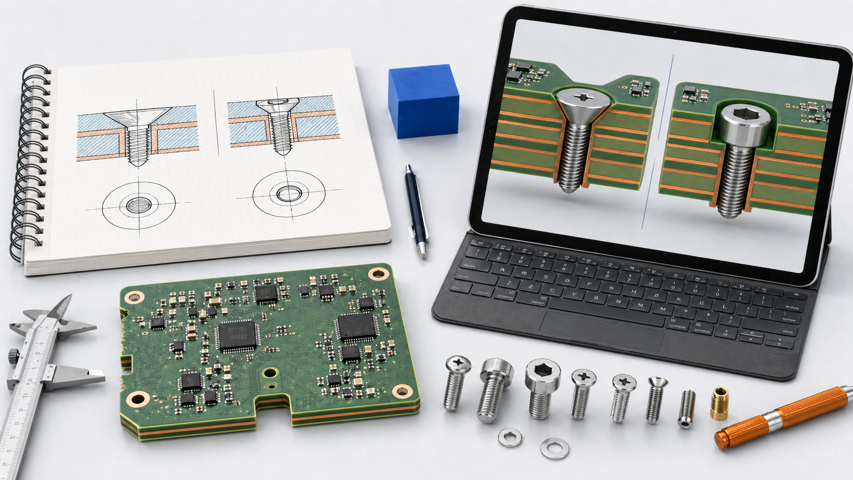
Engineer reviewing counterbore and countersink cross-sections in a PCB fabrication drawing

Counterbore vs Countersink Size and Depth

Counterbore vs countersink size must come from the selected screw and the finished PCB stack-up; there is no universal recess diameter or depth that is safe for every board. The head diameter sets the minimum functional recess, while tolerance, installation access, board thickness, copper clearance, and inspection capability determine the final drawing values.

How deep should a counterbore be?

A counterbore should be deep enough to achieve the required screw-head position, but no deeper than the board can support after worst-case tolerances are applied. Start with the actual head height and desired flushness. Then subtract the maximum pocket depth from the minimum finished board thickness and review the remaining laminate, internal copper, local support, and assembly load.

How should countersink depth be controlled?

Control a countersink with the included angle plus either its maximum diameter or its depth, then verify the final screw position. Angles such as 82 degrees, 90 degrees, and 120 degrees appear in design systems, but none is a universal PCB default. The specified angle must match the purchased flat-head screw.
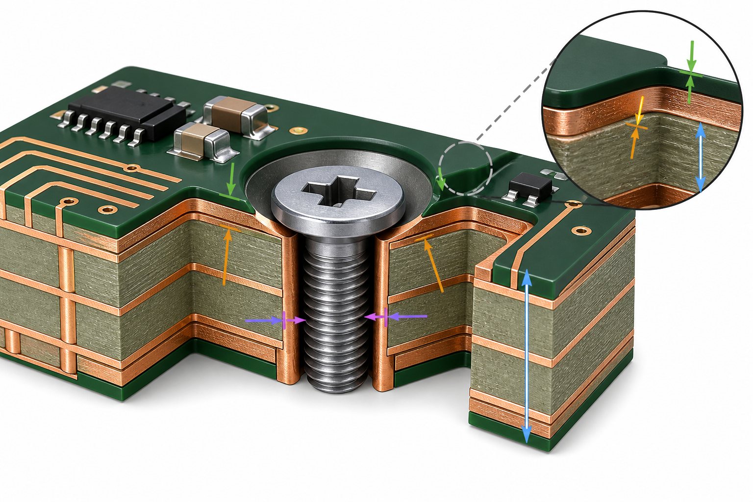
PCB cutaway showing copper keep-out, solder mask opening and remaining laminate around a recessed mounting hole

  • Use minimum finished thickness, not only nominal stack-up thickness.
  • Include recess depth and board thickness tolerances in the worst-case check.
  • Apply copper and solder-mask clearance to the full recess contour.
  • Review edge distance, nearby components, planes, traces, test points, and enclosure metal.
  • Move the recess to a bracket or enclosure when the PCB cannot retain enough material.

Counterbore vs Countersink Screws

Counterbore vs countersink screws are matched by head geometry rather than thread size alone. Flat-head screws need a countersink with a matching underside angle. Socket-head cap screws and other cylindrical heads normally need a counterbore with a flat floor and adequate driver clearance.

Fastener head Preferred feature Fit check
Flat head Countersink Match included angle and verify flush position
Socket-head cap screw Counterbore Check head diameter, head height, and driver clearance
Pan or button head Usually a clearance hole or counterbore Confirm that the bearing face is supported
Screw with washer Counterbore if recessing is required Size the pocket for both washer and installation tool

Use the fastener supplier’s current drawing. Screws with the same nominal thread can have different head diameters, head heights, and included angles. Include the enclosure boss, standoff, washer, nut, and tightening tool in the mechanical stack-up.

Counterbore vs Countersink vs Spotface

A spotface is a shallow flat-bottom cut made to create a clean local bearing surface, while a counterbore is deep enough to recess a fastener head or related hardware. A countersink is different from both because it creates a conical seat for a flat-head screw.

When to use spotface vs counterbore?

Use a spotface when the screw or washer can remain above the surface but needs a flat, clean seat. Use a counterbore when the head must sit below the original surface. The drawing should identify the intended feature because a shallow counterbore and a spotface can look similar in a simplified top view but communicate different functional requirements.

On a PCB, either flat-bottom feature removes laminate and may cut surface copper. The designer must still define the recess diameter, depth, side, plating condition, and keep-out. Do not use the terms interchangeably or leave the machining depth to interpretation.

Which Counterbore vs Countersink Bit Should Be Used?

The counterbore vs countersink bit must create the required geometry without tearing laminate, exposing unintended copper, or leaving an incorrect bearing surface. A counterbore needs a tool that can produce a controlled cylindrical pocket with a flat floor. A countersink needs a conical cutter with the specified included angle.

Can you counterbore with a regular drill bit?

A regular twist drill is not a reliable counterbore tool because its point produces a conical bottom instead of a controlled flat floor. A fabricator may use a purpose-made counterbore, end-cutting tool, or another qualified CNC process, depending on the diameter, depth, stack-up, and equipment. The drawing should define the finished geometry rather than prescribe an unverified shop method.

Can you countersink with a drill bit?

A standard twist drill does not provide a controlled countersink angle or seating surface. Use a countersink cutter or a qualified machining operation that matches the screw angle. Tool condition, runout, backing support, entry direction, and laminate structure affect chatter, breakout, and surface quality.

Designers should specify the functional result: diameter, angle or depth, side, tolerance, and required screw position. The PCB manufacturer should confirm the production tool and process during DFM review.

How Are Counterbores and Countersinks Drilled in PCBs?

PCB counterbores and countersinks are normally produced as controlled secondary machining features around a defined mounting hole, although the exact sequence depends on the factory process, plating requirement, tool, and panel support. The finished geometry and board condition matter more than assuming one universal drilling sequence.

  1. Verify the released drill data, fabrication drawing, stack-up, finished thickness, and machining side.
  2. Create or reference the finished mounting hole according to its plated or non-plated requirement.
  3. Machine the cylindrical pocket or conical seat with a qualified tool and controlled setup.
  4. Remove burrs or loose laminate without changing the specified diameter, depth, or angle.
  5. Inspect geometry, copper and mask condition, and the fit of the specified production fastener.

Counterhole data may be supported in NC Drill, ODB++, or IPC-2581 outputs, but a human-readable fabrication drawing should still confirm the side, diameter, depth or angle, tolerance, and plating intent. For projects continuing through PCB assembly, include the enclosure stack-up and any installation constraint that affects screw fit or torque.

How to Dimension a Hole With a Counterbore or Countersink?

Dimension the mounting hole and recess as one controlled mechanical feature, with every value needed for machining and inspection. Do not make the fabricator reverse-engineer the screw head or choose between conflicting drill notes, drawings, and 3D models.

  1. Identify hole quantity and XY location from controlled datums.
  2. State whether each recess is on the top, bottom, or both sides.
  3. Specify the finished through-hole diameter and plated or non-plated condition.
  4. Specify the recess diameter.
  5. For a counterbore, specify depth from the machined surface.
  6. For a countersink, specify included angle and either maximum diameter or depth.
  7. Add tolerances based on functional fit and a practical inspection method.
  8. Define the required screw position: flush, below flush, or controlled protrusion.
  9. Show copper, solder-mask, component, and board-edge keep-outs around the complete recess.

Release one controlled value for each dimension. Include Gerber or another accepted PCB image format, drill data, fabrication drawing, stack-up and finished thickness, and a current STEP or mechanical model when enclosure fit is critical. If these sources disagree, production should stop for clarification.

What Are Common Counterboring and Countersinking Mistakes?

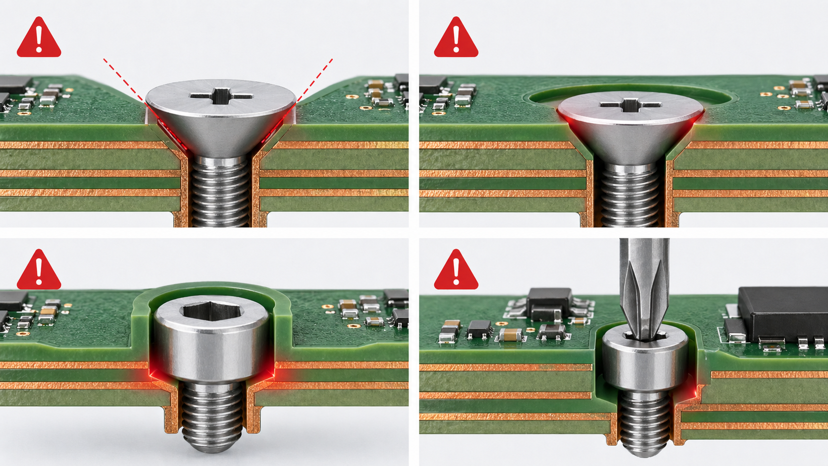
Common counterboring and countersinking mistakes begin with the wrong fastener, incomplete callouts, or clearances based only on the small mounting hole. Most can be found during DFM review before material is removed.

  • The drawing does not state the machined side.
  • The countersink angle does not match the purchased flat-head screw.
  • Counterbore depth is measured from the wrong reference surface.
  • The copper keep-out is based on D1 instead of the larger D2 recess.
  • The feature removes too much laminate from the minimum finished board thickness.
  • The mounting hole’s plated or non-plated condition is missing.
  • The screw head fits, but the driver, washer, standoff, or nearby component does not.
  • An ordinary twist drill is assumed to produce a controlled flat-bottom counterbore.
  • Tolerances are copied from metal machining without considering PCB material or inspection.
  • The drill table, fabrication notes, and mechanical model contain different values.

A DFM review should return these discrepancies to the designer before drilling or routing. EBest Circuit lists countersunk and counterbore-hole work among its FR4 PCB manufacturing support areas, but every special recess still requires project-specific review rather than a generic capability assumption.

How Should the Finished PCB Feature Be Inspected?

Inspection should verify geometry, surface condition, remaining material, and functional fastener fit. A diameter check alone cannot confirm that the screw seats at the required height or that the recess was machined from the correct side.

  1. Confirm hole count, location, machining side, and visible surface condition.
  2. Measure the finished through-hole and recess diameters.
  3. Measure counterbore depth or countersink angle or depth with suitable equipment.
  4. Check for exposed or damaged copper, lifted mask, delamination, burrs, and laminate breakout.
  5. Install the specified production fastener and verify flushness or recessed height.
  6. Confirm driver access and component, standoff, or enclosure clearance.
  7. Where electrical isolation matters, verify separation from copper and chassis metal.
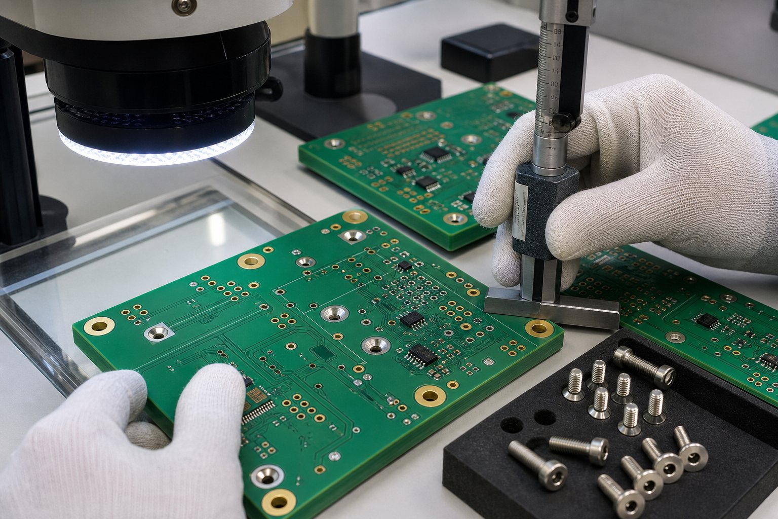
Quality inspection of countersink and counterbore PCB holes with optical measurement and depth checking

For first articles, retain the measurement record and approved fastener-fit sample. These references make later checks more repeatable than a drawing note that only says the screw must be flush.

FAQ About Counterbore vs Countersink

What is the difference between countersink and countersunk?

A countersink is the conical feature or the cutting operation. Countersunk describes a hole or fastener that has already been formed or seated in that feature. For example, a drawing may specify a countersink, while the completed assembly uses a countersunk screw.

Why is it called counter sunk?

The term describes a fastener head being sunk into a prepared conical recess so it can sit flush or below the original surface. In technical writing, “countersink” is the noun or verb for the feature and operation, while “countersunk” usually describes the finished condition.

Can a countersink or counterbore be made on both sides of a PCB?

Yes, if the finished thickness and layer clearances support it. The drawing must identify which features are on the top, bottom, or both sides. Opposing recesses can leave very little laminate, so worst-case depth and thickness need a DFM check.

Should a PCB mounting hole be plated or non-plated?

The choice depends on grounding and mechanical requirements. If the screw connects to chassis ground, define the copper land and plating intent. If isolation is required, define the non-plated hole and full copper keep-out explicitly.

How do I choose the countersink angle?

Use the included angle from the actual flat-head screw specification. Do not assume a regional or CAD default. Confirm the part number, head diameter, and underside angle, then make the PCB callout match that hardware.

What is the correct speed for counterboring?

There is no single correct speed for every PCB counterbore. Tool diameter and material, laminate structure, spindle condition, depth, support, and machine capability all affect the qualified parameters. The manufacturer should set and validate the cutting conditions for the specific job.

Can a counterbore use a washer?

Yes, but the recess diameter and depth must fit both the washer and screw head. Check driver access and confirm that the remaining PCB section can support the wider bearing area without cutting into copper or nearby components.

Does a countersink weaken a PCB?

It can. The conical cut removes laminate around the mounting hole, and a thin board may lose a large share of its local thickness. Risk increases with a large recess, deep seating, limited edge distance, insufficient support, or high installation load.

Can metal-core PCBs use countersunk or counterbored holes?

They may be possible, but the stack-up, dielectric isolation, metal base, plating condition, and machining route require review. Do not transfer an FR4 counterhole design directly to an aluminum- or copper-base board without checking the complete structure.

Are counterhole dimensions stored in drill files?

Supported CAD tools can include counterhole data in NC Drill, ODB++, or IPC-2581 outputs. Even so, include a readable fabrication drawing that confirms the side, recess diameter, depth or angle, tolerance, and plating intent.

What tolerance should I use for a PCB counterhole?

Set tolerance from the functional fit and inspection method, then confirm it with the fabricator. Avoid copying an unnecessarily tight metal-machining tolerance into PCB laminate. The required screw seating position may be more useful than an isolated diameter tolerance.

What should I send for a counterhole DFM review?

Send the PCB image data, drill files, fabrication drawing, stack-up, finished thickness, screw drawing or part number, and STEP model. Include the required screw height, mounting side, enclosure interface, and electrical isolation or grounding requirement.

How Can EBest Circuit Review Your Mounting-Hole Design?

Send us the PCB fabrication package, stack-up, finished thickness, fastener specification, and mechanical model. Our engineering team can review the counterhole callout, machined side, remaining laminate, copper clearance, fastener fit, and assembly constraints before production. For PCB fabrication or full PCBA support, contact EBest Circuit at sales@bestpcbs.com with your Gerber files, quantity, and project requirements.
You may also like

What is the difference between countersink vs counterbore in PCBs?
Thursday, April 30th, 2026

In PCB mechanical design, countersink vs counterbore is mainly about screw head shape, mounting height, contact surface, and how much board material must be removed. A countersink hole has a conical recess for a flat-head screw, so the screw can sit flush with the PCB or enclosure surface. A counterbore hole has a straight cylindrical recess with a flat bottom, so a socket head screw, cap screw, or shoulder screw can sit below or level with the surface while keeping a flat bearing area. For PCB and electronic assembly, this choice affects assembly clearance, insulation distance, board strength, enclosure fit, torque stability, and even manufacturability.

What is counterbore vs countersink?

A countersink is a cone-shaped cut made at the top of a hole. It is designed for screws with a tapered head. When the screw is tightened, the angled underside of the screw head matches the angled recess. This allows the screw head to sit flush with the board, panel, or enclosure surface. In PCB mounting, countersinking is often used when the board must fit tightly into a housing, when the screw head should not protrude, or when the assembly needs a cleaner, low-profile finish.

A counterbore is different. It is a cylindrical recess made around a hole, usually with a flat bottom. The screw passes through the smaller central hole, while the screw head sits inside the larger recessed area. This style is common for socket head cap screws, cheese head screws, shoulder screws, spacers, and some machine screws used in stronger mechanical assemblies. For PCBs, a counterbore can provide a more stable seating surface because the screw head presses against a flat surface rather than a conical surface.

The difference looks simple, but it matters in PCB manufacturing. A printed circuit board is not just a piece of plastic. It may contain copper layers, plated through holes, solder mask, silkscreen, glass fiber, controlled impedance traces, ground planes, and clearance areas. Removing material for a countersink or counterbore can expose laminate, cut into copper, reduce board thickness around the mounting area, or create unexpected stress around the hole. That is why these features should be defined clearly in the mechanical drawing and checked during DFM review.

In engineering drawings, counterbore vs countersink symbols are also different. A countersink is usually shown with a V-shaped symbol, often written as “⌵” followed by the major diameter and angle. A counterbore is usually shown with a square-bottom symbol, often written as “⌴” followed by the recess diameter and depth. PCB fabrication drawings may also use notes such as “CSK Ø6.0 x 90°” or “C’BORE Ø6.0 x 1.2 mm deep.” The exact notation depends on the customer’s CAD system, drawing style, and manufacturing standard.

FeatureCountersink HoleCounterbore Hole
Recess shapeConical, angledCylindrical, flat-bottom
Typical screw typeFlat-head screwSocket head cap screw, shoulder screw, pan head screw
Seating surfaceAngled surfaceFlat surface
Main visual resultScrew head sits flushScrew head sits recessed or level
Common drawing symbol
Important dimensionsMajor diameter and angleRecess diameter and depth
PCB concernAngle control, copper clearance, laminate thinningDepth control, remaining board thickness, flatness

For a PCB supplier such as EBest Circuit (Best Technology), this is not treated as a small drilling detail only. It is part of mechanical reliability. During PCB or PCBA review, the engineering team needs to confirm hole size, screw standard, board thickness, plating requirements, copper keep-out, and whether the feature is processed before or after surface finish. When the documentation is precise, the finished assembly is easier to build and inspect.

countersink vs counterbore advantages

The advantages of each option depend on what the PCB needs to do in the final product. A countersink is excellent when the goal is a flush surface, smooth appearance, or minimum mechanical height. A counterbore is stronger when the design needs stable clamping, a flat screw seat, controlled screw depth, or better load distribution around the mounting hole.

The main advantage of a countersink hole is the clean, low-profile fit. Flat-head screws can sit level with the PCB surface, which helps when the board slides into a narrow enclosure or when another part must sit close above it. This is useful in handheld electronics, compact control modules, display assemblies, sensor boards, keyboard structures, and some automotive or industrial housings. A countersink can also improve appearance because the screw head does not stand proud of the surface.

A counterbore hole offers a different kind of advantage. Because the recess has a flat bottom, the screw head can apply force more evenly. This is useful when the PCB is mounted to metal standoffs, heat sinks, brackets, or structural carriers. A counterbore also allows the use of stronger screw types. Socket head cap screws, for example, can handle higher installation torque than many flat-head screws. This can be valuable when the PCB assembly must remain secure under vibration, repeated service, or thermal cycling.

For electronic assembly, the practical advantage is often not only the screw style. It is also the control of spacing. A counterbore can recess a screw head while keeping the top surface predictable. A countersink can reduce height but may concentrate force along an angled surface. When FR4, ceramic substrate, aluminum PCB, or heavy copper PCB is involved, that difference can influence how much pressure the board can safely handle.

Comparison PointCountersink AdvantageCounterbore Advantage
Assembly heightVery low profileControlled recessed height
AppearanceClean flush surfaceNeat recessed screw head
Screw strengthGood for flat-head screwsStronger with cap screws or shoulder screws
Load distributionDepends on angle matchBetter flat bearing area
PCB thickness usageCan be efficient on thicker boardsNeeds enough thickness for recess depth
ServiceabilityGood for simple accessExcellent for repeat assembly
Vibration resistanceGood when designed wellOften stronger with proper screw and washer design

There are also cost and production considerations. Countersinking usually requires angle control. Counterboring requires depth control and enough remaining material under the recess. Neither choice is automatically better. The better choice is the one that fits the screw, the enclosure, the PCB material, and the assembly process.

For EBest Circuit, this is where DFM review becomes useful. A drawing may show a counterbore vs countersink hole clearly, but the factory still needs to check if the feature is compatible with actual board thickness, nearby copper, solder mask opening, surface finish, panelization method, and final PCBA mounting. A small mechanical feature can become a high-value design detail when it prevents assembly interference later.

When to use countersink vs counterbore?

Use a countersink when the screw head must sit flush and the design uses a flat-head screw. This is common when there is limited vertical space, when the PCB is mounted behind a panel, or when a smooth surface is needed for shielding, insulation film, labels, keypads, or nearby mechanical parts. A countersink hole is also suitable when the screw head should guide itself into position during assembly. The angled geometry can help center the screw, provided the hole and recess are machined accurately.

Use a counterbore when the screw head needs to sit inside the board or panel while keeping a flat contact area. This is often preferred when the PCB is part of a more robust mechanical stack-up. Examples include boards mounted to heat sinks, power modules fixed to metal plates, industrial controller boards, automotive electronics, and assemblies where socket head screws are preferred for torque control. Counterbore mounting can also work well when a washer, spacer, or shoulder feature is involved.

PCB thickness is one of the first checks. If the board is thin, countersinking may remove too much material around the hole. If the countersink angle is deep, the remaining laminate may become weak. For a counterbore, the recess depth must leave enough board material to support the screw head and maintain mechanical stability. A 1.6 mm FR4 PCB, for example, gives limited depth for a counterbore. A thicker PCB, aluminum PCB, or mechanical carrier may provide more room.

Copper clearance is another major factor. Mounting holes should usually have copper keep-out unless they are intentionally connected to chassis ground or a metal mounting point. If a countersink or counterbore cuts into copper, it can expose copper edges or create unwanted electrical contact with a screw. This matters in high-voltage boards, battery systems, power supplies, motor controllers, automotive modules, and any assembly where creepage and clearance are part of the safety design.

In simple terms, use countersink for flush fit and use counterbore for flat, strong, recessed mounting. That rule works for many PCB projects. The final decision should still include screw type, board thickness, enclosure stack-up, torque requirement, insulation distance, and manufacturing tolerance.

  • Choose a countersink when the final surface must stay flat and the screw is a flat-head type.
  • Choose a counterbore when the screw head needs a flat seat and stronger mechanical holding.
  • Choose neither if a normal clearance hole with a standoff gives better reliability and lower cost.
  • Ask for DFM feedback when the hole is close to copper, board edges, slots, components, or high-voltage areas.

This is especially important for PCBA. A board may look correct at PCB fabrication stage, but assembly can reveal interference with connectors, heat sinks, shields, cables, screwdrivers, or automated test fixtures. EBest Circuit often reviews these mechanical details early because a clean mounting solution helps the entire product feel more refined and easier to assemble.

What type of fastener fits a countersink hole perfectly?

A countersink hole is designed for a flat-head screw, sometimes called a countersunk screw. The underside of the screw head has an angled surface that matches the cone-shaped recess in the board or panel. When the screw is tightened, the head settles into the countersink and becomes flush or nearly flush with the surface.

The most important detail is the angle. Flat-head screws are not all the same. In many inch-based screw systems, an 82-degree flat-head screw is common. In many metric systems, 90 degrees is common. Some aerospace and specialty fasteners use 100 degrees. If the screw angle and countersink angle do not match, the screw may contact only at the top edge or bottom edge of the recess. That creates uneven stress and can reduce the quality of the assembly.

For PCBs, the screw head should also be selected with the board material in mind. FR4 is durable, but it is still a laminated composite. It does not behave like steel or aluminum. If the screw is tightened too aggressively, the angled head can press into the laminate. A properly designed countersink gives a clean fit, but the assembly process should use controlled torque. This is especially useful when the product must be assembled repeatedly during repair, testing, or field service.

Flat-head machine screws are common in electronic products. They may be used with metal inserts, threaded standoffs, nuts, or enclosure bosses. Self-tapping flat-head screws may also be used in plastic housings, but they need careful control because the thread-forming force can add stress to the PCB or the enclosure. In higher-reliability electronics, machine screws with metal standoffs often provide a more predictable result.

For a countersink vs counterbore hole decision, the screw head shape should come before the hole style. Do not choose a countersink first and then search for a screw later. The better process is to select the screw family, confirm the head angle, define the mounting stack-up, and then calculate the countersink diameter and depth. This keeps the PCB drawing practical.

Fastener TypeFit for Countersink HoleNotes for PCB Use
Flat-head machine screwExcellentBest match when angle is correct
Flat-head self-tapping screwPossibleMore common with plastic bosses than metal standoffs
Oval-head screwSometimesHead may not sit fully flush
Pan-head screwPoorDesigned for flat surface seating
Socket head cap screwPoorBetter suited for counterbore
Shoulder screwUsually poorOften needs counterbore or precision clearance

A countersink hole works best when the screw head is not used as an electrical path unless the design intentionally requires chassis grounding. If the screw is connected to ground, the copper land, plating, surface finish, washer, and corrosion behavior should be planned. If it is isolated, the keep-out area needs enough clearance around the full countersink diameter, not just the drilled hole.

What kind of screws are used for counterbore hole mounting?

Counterbore hole mounting commonly uses screws with a straight-sided or flat-bottom head. The most familiar choice is the socket head cap screw. This screw has a cylindrical head and an internal hex drive. The head can sit neatly inside the counterbore recess while the underside presses against a flat surface. This makes it a strong and reliable option for assemblies that need firm clamping.

Pan head screws, cheese head screws, button head screws, and shoulder screws may also be used with counterbore holes, depending on the design. The point is not always to hide the screw completely. Sometimes the purpose is to control screw head location, protect surrounding parts, or keep the screw from interfering with a cover, bracket, cable path, or neighboring PCB. A counterbore gives the designer a defined pocket for the screw head.

In PCB assemblies, counterbore mounting is often selected when the board is part of a thicker mechanical structure. For example, an aluminum PCB may be fastened to a heat sink using screws that need firm pressure. A power electronics board may be mounted to a metal baseplate. A control board may be fixed inside an industrial enclosure where vibration resistance matters. In these cases, the screw head style and tightening method have a direct effect on assembly quality.

A counterbore can also be used with a washer if there is enough recess diameter. The washer can spread the force, protect the PCB surface, and improve consistency during tightening. However, the counterbore diameter must be large enough for both the screw head and washer. The drawing should state this clearly because a standard counterbore made only for the screw head may not fit a washer.

For higher-volume PCBA, the screw drive style matters as well. Hex socket, Torx, and Phillips drives each behave differently during assembly. A hex socket or Torx screw may provide better torque control and lower cam-out risk. This helps when assembly technicians need repeatability. If the screw is installed by automatic equipment, the head type, drive depth, and access clearance become even more important.

Common screws used with counterbore hole mounting include:

  • Socket head cap screws for stronger clamping and clean recessed mounting.
  • Pan head or cheese head machine screws when a flat seating surface is needed.
  • Shoulder screws when alignment, rotation, or controlled spacing is required.
  • Screws used with washers when load spreading is more important than minimum size.
  • Captive screws in serviceable electronic equipment where repeated access is expected.

Counterbore mounting is a strong choice when the PCB needs mechanical confidence. It allows the designer to create a controlled screw pocket while preserving a flat contact zone. The tradeoff is that the board or carrier must have enough material for the recess. That is why counterbore depth, remaining thickness, hole tolerance, and surface finish should be reviewed before production.

What is the purpose of a counterbore?

The purpose of a counterbore is to create a flat-bottom recess that allows a screw head, washer, spacer, or shoulder feature to sit below or level with a surface. In PCB design, this helps control assembly height, improve fastening stability, and create a cleaner mechanical interface. It is especially useful when the screw head cannot protrude above the board surface but a flat seating area is still needed.

A counterbore also provides better load distribution than many angled recesses. Because the bottom of the recess is flat, the screw head can press against a more predictable surface. This is valuable for assemblies that need repeatable torque. In electronics, that can include products exposed to vibration, heat, movement, or service cycles. A secure screw joint helps the board stay aligned with connectors, displays, sensors, heat sinks, and enclosure features.

Another purpose is to protect nearby components. In compact electronics, screw heads can interfere with covers, cables, battery packs, metal shields, or other boards. A counterbore lowers the screw head and creates extra clearance. This can make the whole assembly easier to package. It also gives industrial designers more freedom because the mechanical fastening does not disturb the outer shape of the product.

Counterbores can also support precise spacing. A shoulder screw or custom fastener can sit in a recess to control alignment. This is useful when a PCB must match an optical path, sensor window, connector cutout, or metal frame. In such designs, the mounting hole is not only a hole. It becomes part of the mechanical positioning system.

In manufacturing, the counterbore must be controlled carefully. The recess diameter should fit the screw head with enough clearance. The depth should place the screw head at the desired height. The bottom surface should be clean and flat enough for the intended function. If the board is multilayer, the designer must make sure that the counterbore does not cut into inner-layer copper, ground planes, or power planes. The same concern applies to countersink holes, but counterbore depth can be easier to overlook because the recess looks simple on a drawing.

For PCB and PCBA projects, EBest Circuit recommends defining counterbore details in a mechanical drawing or fabrication note, not only in Gerber files. Gerber data may show hole positions, but it may not communicate full recess depth, diameter, tolerance, screw type, or special requirements. A complete drawing helps the fabrication team produce the correct feature and helps the assembly team verify the final fit.

What are common counterboring mistakes?

Counterboring mistakes usually come from incomplete mechanical definition, weak tolerance control, or a lack of coordination between PCB layout and enclosure design. The feature may look easy, but a counterbore removes real material from the board. If the designer treats it as a simple hole enlargement, problems may appear during assembly.

One common mistake is making the counterbore too deep. A deep recess may leave very little material under the screw head. On a thin FR4 board, this can reduce strength around the mounting hole. On a multilayer PCB, it may also get too close to internal copper layers. If the board has heavy copper or high-current planes, this can create a serious manufacturing concern. The better approach is to define a safe remaining thickness and keep copper away from the full counterbore area.

Another mistake is choosing a recess diameter that is too tight. Screws have tolerances. Plating, surface finish, solder mask, and fabrication variation can also affect fit. If the counterbore diameter barely matches the screw head, the screw may bind during assembly. This slows production and may damage the board surface. A little practical clearance helps the screw sit properly and makes manual or automated installation smoother.

A third mistake is ignoring the washer or tool access. A drawing may show a screw head inside the recess, but the real assembly may use a washer or require a screwdriver bit with enough room. If the recess does not provide enough space, the assembly technician may struggle to install the screw cleanly. In volume production, that small issue can create avoidable handling time.

Counterboring near copper, traces, or components is another frequent issue. The recess diameter is larger than the drilled hole, so the keep-out area must follow the outer counterbore diameter. Designers sometimes clear copper around the center hole only, then discover that the counterbore cuts into copper or solder mask. For safer PCB design, copper clearance should be checked around the entire machined feature.

Counterboring MistakeWhy It MattersBetter Practice
Recess too deepWeakens the board and may approach inner copperDefine maximum depth and remaining thickness
Diameter too smallScrew head may bindAdd practical clearance based on screw tolerance
Copper too closeRisk of exposed copper or unwanted contactUse keep-out around full recess diameter
Washer not consideredAssembly may not fit as expectedConfirm full hardware stack-up
Tool access ignoredSlower or less consistent assemblyCheck screwdriver bit clearance
Missing drawing notesFabricator may interpret incorrectlyState diameter, depth, tolerance, and screw type

Counterboring is very effective when it is designed with the full assembly in mind. It becomes easier and more reliable when the PCB designer, mechanical engineer, and manufacturer agree on the exact screw, board thickness, mounting surface, and final product requirements.

What are common countersinking mistakes?

Countersinking mistakes often come from angle mismatch, excessive depth, or poor clearance planning. A countersink depends on proper contact between the flat-head screw and the conical recess. If the screw angle and recess angle do not match, the screw may sit proud, wobble, or press unevenly into the laminate. In a PCB, uneven stress can create cosmetic issues, mechanical weakness, or assembly inconsistency.

One of the most common mistakes is using the wrong countersink angle. A designer may call out a countersink but forget to specify whether the screw head is 82 degrees, 90 degrees, or 100 degrees. The factory may then use a default angle, while the purchasing team may buy a different screw standard. The result is a poor fit. A proper drawing should state the countersink angle and the intended screw standard.

Another mistake is countersinking too deeply. A deep countersink can remove too much laminate around the mounting hole. This can be especially risky on thinner PCBs. The screw may sit flush, but the board may lose mechanical support at the hole edge. If the screw is tightened with high torque, the angled head can act like a wedge. Good design balances flush height with enough remaining material.

Copper clearance is also important. A countersink hole has a larger diameter at the top surface than the drilled hole. If copper is only cleared around the drill size, the angled cut may expose copper. This can matter in grounding design, insulation control, and appearance. The copper keep-out should cover the full countersink major diameter, plus a reasonable safety margin.

Surface finish and solder mask should also be considered. ENIG, HASL, OSP, immersion silver, or other finishes may behave differently around machined features. If the countersink is made after surface finish, exposed laminate may remain visible. If the countersink is made before finish, coverage and process compatibility should be checked. For many PCB mounting holes, the simplest and most robust option is to keep the countersink as a mechanical non-plated feature unless the design has a clear reason for electrical connection.

A countersink can also create assembly concerns when components are too close to the hole. A flat-head screw needs tool access, and the screw head diameter may be larger than expected. If a connector, tall capacitor, shield can, or cable sits near the mounting point, the screw may be hard to install. Early mechanical review can prevent this.

Good countersinking starts with the screw. Confirm the screw head diameter, angle, drive type, finish, torque target, and mounting stack. Then define the PCB feature. When this order is followed, the final counterbore vs countersink hole decision becomes much easier and more practical.

Which option works better for PCB and electronic assembly?

For PCB and electronic assembly, the better option depends on the mechanical purpose. A countersink works better when the product needs a flush screw head, low height, and a clean surface. A counterbore works better when the product needs stronger clamping, a flat screw seat, recessed hardware, or better torque control. In many professional electronic assemblies, counterbore mounting is often more forgiving because it gives the screw head a flat bearing area. However, countersink mounting remains the right choice when flush fit is the main requirement.

For standard FR4 PCBs, both options should be used carefully. A normal clearance hole with standoff support is often the simplest and most economical mounting method. Countersink and counterbore features should be used when they solve a real assembly need. That need may be enclosure clearance, screw height reduction, vibration resistance, heat sink attachment, or improved product appearance. When the feature has a clear purpose, it can add real value to the design.

For thin PCBs, countersinking can be challenging because the conical cut may remove too much material. Counterboring can also be limited because there may not be enough thickness for a useful recess. In these cases, designers may use a thicker local mechanical support, a metal bracket, a standoff, a molded boss, or a separate enclosure feature instead of cutting deeply into the board.

For aluminum PCBs, ceramic PCBs, heavy copper PCBs, and high-power assemblies, the mounting decision becomes more important. These boards often connect to heat sinks, metal bases, or structural parts. A counterbore may provide better screw seating and torque control, especially when heat transfer and pressure distribution matter. A countersink may still be used for a flush surface, but the screw force and material behavior should be checked carefully.

For high-reliability electronics, the best answer is not simply “countersink” or “counterbore.” The best answer is a verified mounting design. The screw, hole, board thickness, copper clearance, enclosure boss, standoff, torque, and assembly sequence should work together. This is where a capable PCB and PCBA manufacturer can help.

EBest Circuit (Best Technology) supports PCB fabrication, PCBA assembly, component sourcing, and engineering review for electronic products across industrial, medical, automotive, communication, power, and embedded control applications. For mechanical features such as countersunk holes, counterbored holes, plated and non-plated mounting holes, cutouts, slots, and enclosure-related PCB details, the team can review manufacturability before production. This helps customers reduce assembly surprises and build boards that fit the final product with confidence.

PCB Assembly SituationBetter ChoiceReason
Need a flush screw headCountersinkFlat-head screw sits level with the surface
Need stronger clampingCounterboreFlat screw seat supports more stable pressure
Thin PCB with limited materialUsually standard clearance holeLess material removal is safer
Board mounted to heat sinkOften counterboreBetter contact control and torque consistency
Cosmetic product surfaceCountersinkCleaner low-profile appearance
Vibration-sensitive assemblyOften counterboreWorks well with cap screws and controlled torque
Tight enclosure clearanceDepends on screw typeCountersink for flush fit, counterbore for recessed cap screw
High-voltage PCBDepends on clearanceCopper and insulation spacing must be reviewed

In short, choose countersink for a smooth, flush, space-saving mount. Choose counterbore for a stronger, flatter, more controlled mounting pocket. For PCBs, the winning design is the one that respects board thickness, copper clearance, screw geometry, assembly torque, and enclosure fit. When these details are reviewed early, the final PCBA looks cleaner, installs faster, and performs with stronger long-term reliability.

If you are designing a PCB that needs countersink holes, counterbore holes, precision mounting holes, enclosure fit review, or full PCBA support, contact EBest Circuit (Best Technology) at sales@bestpcbs.com.

You may also like