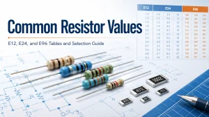
common resistor values are standardized resistance numbers arranged in preferred E-series. Common examples include 10 Ω, 22 Ω, 47 Ω, 100 Ω, 220 Ω, 470 Ω, 1 kΩ, 4.7 kΩ, 10 kΩ, and 100 kΩ. The correct choice still depends on circuit function, tolerance, power, voltage, temperature, and package availability.
This guide provides a practical lookup chart and explains how to move from a calculated resistance to a part that can be specified, purchased, assembled, and tested on a PCB.
What Are Common Resistor Values?
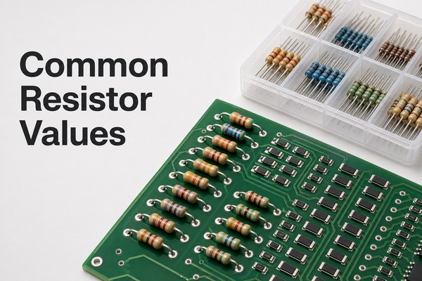
Common resistor values are preferred numbers repeated across resistance decades. Instead of manufacturing every possible value, suppliers offer structured series such as E6, E12, E24, and E96.
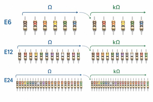
The number after the letter E indicates how many nominal values appear in one decade. For example, E12 has 12 values between 10 and 100. Those values repeat by multiplying or dividing by powers of ten, so 47 becomes 4.7 Ω, 47 Ω, 470 Ω, 4.7 kΩ, and 47 kΩ.
- E6: six broad steps per decade, often associated with wide-tolerance parts.
- E12: twelve steps per decade and a familiar general-purpose set.
- E24: twenty-four steps per decade, widely used for 5% parts.
- E48 and E96: finer spacing for tighter-value selection, commonly used with 2% and 1% parts.
Why Do Resistor Values Follow E-Series Numbers?
E-series numbers create approximately even percentage steps across each decade. This spacing gives designers enough choices to match a tolerance class without filling catalogs with nearly indistinguishable nominal values.
IEC 60063 defines preferred number series for resistors and capacitors. The system also supports consistent marking, inventory, schematic review, BOM preparation, and alternate-part sourcing. However, the series alone does not guarantee that a value exists in every package, power rating, technology, or tolerance.
Common Resistor Values Chart
The following common resistor values chart lists the base values within one decade. Multiply each number by 0.1, 1, 10, 100, 1,000, or another power of ten to obtain the required range.
| Series | Base values in one decade | Common tolerance association |
|---|---|---|
| E6 | 10, 15, 22, 33, 47, 68 | 20% |
| E12 | 10, 12, 15, 18, 22, 27, 33, 39, 47, 56, 68, 82 | 10% |
| E24 | 10, 11, 12, 13, 15, 16, 18, 20, 22, 24, 27, 30, 33, 36, 39, 43, 47, 51, 56, 62, 68, 75, 82, 91 | 5% |
| E48 | 48 preferred values per decade | 2% |
| E96 | 96 preferred values per decade | 1% |
These tolerance relationships are common design conventions, not a promise about every product family. Always verify the manufacturer’s series, resistance range, tolerance, and package options before releasing a BOM.
How Do E6, E12, E24, and E96 Resistor Values Differ?
The series differ mainly in the number of available nominal values per decade. A denser series lets the selected nominal resistance sit closer to the calculated target.
- E6 is suitable when the circuit can tolerate coarse steps.
- E12 resistor values cover familiar general-purpose choices such as 1 kΩ, 1.2 kΩ, 1.5 kΩ, and 1.8 kΩ.
- Common resistor values E24 add intermediate choices such as 1.1 kΩ, 1.3 kΩ, 1.6 kΩ, and 2.0 kΩ.
- E96 resistor values provide much finer spacing, including 1.00 kΩ, 1.02 kΩ, 1.05 kΩ, and 1.07 kΩ.
A tighter E-series does not automatically make a circuit more accurate. Reference tolerance, temperature coefficient, source variation, leakage, input impedance, and layout can dominate the error budget.
How Do You Scale Preferred Values Across Ohm Decades?
Scale a preferred base number by a power of ten, then write the result with an unambiguous unit. The base value 47, for example, produces 4.7 Ω, 47 Ω, 470 Ω, 4.7 kΩ, 47 kΩ, and 470 kΩ.
| Base value | Examples across decades |
|---|---|
| 10 | 1 Ω, 10 Ω, 100 Ω, 1 kΩ, 10 kΩ, 100 kΩ |
| 22 | 2.2 Ω, 22 Ω, 220 Ω, 2.2 kΩ, 22 kΩ, 220 kΩ |
| 47 | 4.7 Ω, 47 Ω, 470 Ω, 4.7 kΩ, 47 kΩ, 470 kΩ |
| 68 | 6.8 Ω, 68 Ω, 680 Ω, 6.8 kΩ, 68 kΩ, 680 kΩ |
When a BOM is shared internationally, use Ω, kΩ, and MΩ consistently. In compact markings, the unit letter may replace the decimal point: 4R7 means 4.7 Ω, while 4K7 means 4.7 kΩ.
What Are Common Resistor Values for LED Circuits?
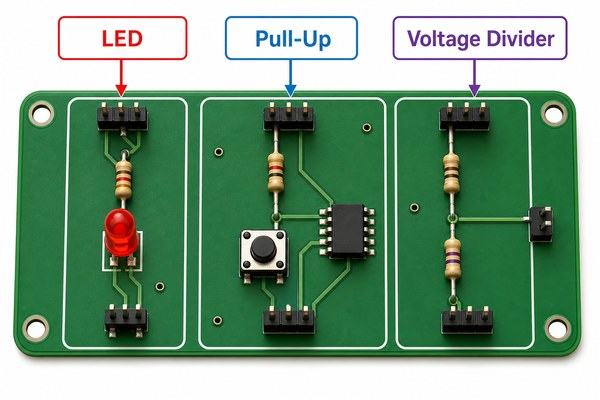
Common resistor values for LED circuits often fall between 100 Ω and 1 kΩ, but the value must be calculated from supply voltage, LED forward voltage, and target current. Use R = (Vsupply − Vforward) / I, then select the next suitable preferred value and verify brightness.
For a 5 V supply, a red LED with a 2.0 V forward drop, and a 10 mA target current, the calculation gives 300 Ω. A 330 Ω preferred value lowers current slightly and provides margin. The resistor dissipates about 0.03 W in this example, but transient conditions and ambient temperature still need review.
- Use the LED datasheet’s forward-voltage range, not color alone.
- Calculate the worst case at maximum supply voltage and minimum forward voltage.
- Confirm resistor power with P = I²R or P = VI.
- Prototype brightness before freezing the production BOM.
For a more focused calculation workflow, see how to choose a current-limiting resistor for an LED.
What Are Common Pull Up Resistor Values?
Common pull up resistor values are 1 kΩ, 2.2 kΩ, 4.7 kΩ, 10 kΩ, 47 kΩ, and 100 kΩ. Values around 4.7 kΩ or 10 kΩ are frequent starting points for ordinary digital inputs, but bus speed, capacitance, leakage, supply voltage, and sink-current limits determine the final value.
A lower resistance creates a faster rising edge and stronger logic-high bias, while drawing more current when the node is low. A higher resistance reduces static current but makes the node more sensitive to leakage and noise and increases the RC rise time.
- For open-drain buses, calculate rise time from pull-up resistance and total bus capacitance.
- For buttons and configuration pins, check input leakage and the internal pull-up specification.
- For noisy or long connections, verify the level on real hardware rather than relying on a generic value.
What Are Standard SMD Resistor Values?
Standard SMD resistor values normally follow the same preferred E-series as through-hole parts. Package style changes the mounting method and electrical limits; it does not create a different basic sequence of nominal resistance values.
Three-digit and four-digit markings may identify resistance on parts large enough to carry a code. Very small 0402 and 0603 parts may be unmarked, so the reel label, BOM, feeder setup, and traceability records become essential.
For package dimensions and code examples, use the SMD resistor package sizes chart alongside the selected manufacturer datasheet.
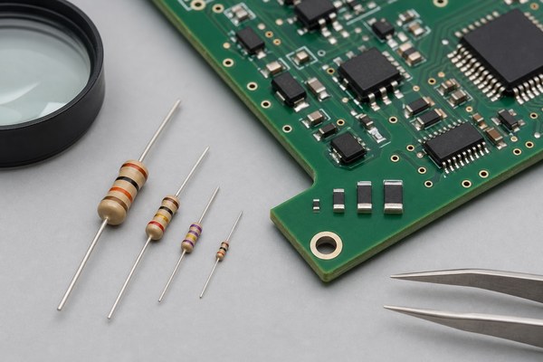
How Do 0402 and 0603 Package Sizes Affect Selection?
0402 and 0603 package sizes affect assembly yield, power dissipation, working voltage, pulse capability, pad geometry, and inspection. They do not determine the nominal resistance by themselves.
Common 0402 resistor values and common resistor values 0603 can overlap widely, yet the available range changes by manufacturer and resistor technology. A value that exists as a general-purpose 0603 thick-film part may not exist with the same tolerance, voltage rating, or pulse rating in 0402.
- Use 0402 where density matters and the assembly process supports its placement tolerances.
- Use 0603 when extra handling margin, readability, or dissipation is useful.
- Check land patterns against the selected component datasheet.
- Avoid substituting package sizes without reviewing pad geometry and ratings.
How Do Tolerance, Power, and Voltage Change the Choice?
Tolerance sets the permitted initial resistance deviation, power rating limits steady dissipation under stated conditions, and working voltage limits the voltage that may be applied across the body. All three must pass; a correct nominal value alone is insufficient.
- Tolerance: use the circuit error budget to decide whether 5%, 1%, or a tighter part is justified.
- Power: calculate worst-case dissipation and apply the manufacturer’s temperature derating curve.
- Voltage: verify maximum working voltage even when calculated wattage is low.
- Temperature coefficient: include resistance drift when the operating range is wide.
- Pulse or surge load: check dedicated pulse curves for inrush, discharge, or switching events.
Do not treat a package’s headline wattage as an unconditional PCB-level capability. Copper area, ambient temperature, neighboring heat sources, airflow, and enclosure conditions affect the real margin.
How Should You Select Values for Dividers, Bias, and Current Sensing?
Select resistance ratios for dividers and bias networks first, then choose the absolute impedance level that meets current, noise, leakage, bandwidth, and source-loading limits. For current sensing, begin with the required sense voltage and allowable power loss.
A divider may use 10 kΩ and 10 kΩ for a one-half ratio, or 100 kΩ and 100 kΩ for the same ideal ratio. The higher pair draws less current but is more affected by leakage and input impedance. The lower pair loads the source more heavily.
Where matched ratios matter, a resistor network may improve tracking and simplify placement. Current-sense resistors require separate checks for Kelvin routing, TCR, power, and pulse energy.
Which Resistor Values Should You Stock for Prototyping?
A practical prototype stock should cover each decade with common E12 or E24 values and include extra quantities of values used repeatedly in digital, analog, LED, and interface circuits.
A compact starting set might include 10 Ω, 22 Ω, 47 Ω, 100 Ω, 220 Ω, 330 Ω, 470 Ω, 1 kΩ, 2.2 kΩ, 4.7 kΩ, 10 kΩ, 22 kΩ, 47 kΩ, 100 kΩ, 220 kΩ, 470 kΩ, and 1 MΩ. Add 0 Ω jumpers, low-ohm current-sense parts, and precision values only when the project requires them.
- Separate 1% and 5% stock to prevent silent substitutions.
- Label package, resistance, tolerance, and power clearly.
- Keep SMD reels or cut tape traceable to the manufacturer part number.
- Measure loose or uncertain parts before installation.
If 10 kΩ appears frequently in your designs, the 10K ohm resistor identification guide explains its color bands and verification steps.
How Do You Convert a Calculated Resistance to an Available Part?
Convert a calculated resistance by choosing the nearest preferred value that keeps the full circuit within its permitted limits. Do not automatically round up or down; the safe direction depends on the function.
- Calculate the ideal resistance using worst-case circuit conditions.
- Identify the acceptable minimum and maximum resistance.
- Choose an E-series value inside that window.
- Apply tolerance to the candidate value and repeat the worst-case check.
- Verify power, voltage, TCR, package, and supplier availability.
- Update the schematic, BOM, footprint, and assembly notes with one exact orderable part.
For an LED limiter, rounding to a higher resistance usually lowers current. In a feedback divider or timing network, either direction may shift the target beyond specification. The calculation must follow the circuit’s real failure mode.
What Mistakes Cause Resistor Value Problems on a PCB?
Most resistor-value problems come from unit errors, unreviewed substitutions, incorrect markings, or missing worst-case checks rather than from the E-series itself.
- Confusing 4.7 Ω, 4.7 kΩ, and 4.7 MΩ
- Entering 100 instead of 100 kΩ in the BOM
- Treating an E96 code as a simple three-digit marking
- Using typical LED forward voltage instead of the datasheet range
- Ignoring working voltage because calculated power is low
- Changing 0402 to 0603 without updating the footprint
- Allowing a substitute with the right resistance but the wrong pulse or TCR rating
These errors are easier to prevent when the schematic, BOM, pick-and-place data, and assembly drawing use consistent units and manufacturer part numbers. Use this common resistor values reference as a starting point, then validate the exact component datasheet.
FAQ About Common Resistor Values
What are the most common resistor values?
Frequently used values include 100 Ω, 220 Ω, 330 Ω, 470 Ω, 1 kΩ, 2.2 kΩ, 4.7 kΩ, 10 kΩ, 47 kΩ, and 100 kΩ. Their popularity does not make them correct for every circuit.
What are some common resistor values in ohms?
Common resistor values ohms lists often begin with 1 Ω, 2.2 Ω, 4.7 Ω, 10 Ω, 22 Ω, 47 Ω, 100 Ω, 220 Ω, 330 Ω, 470 Ω, and 680 Ω before continuing into kilohms.
Is 100 ohms a standard resistor value?
Yes. 100 Ω is a preferred value in the major E-series and is widely available in many tolerances, packages, and technologies.
Is 330 ohms a common resistor value?
Yes. 330 Ω is a common E12/E24 value and is often used for indication LEDs and general current limiting when calculations support it.
Why is 4.7 kΩ more common than 5 kΩ?
4.7 kΩ belongs to widely used preferred series. Exactly 5.0 kΩ is available in finer series and precision families, but 4.7 kΩ is more common in general-purpose assortments.
Should I always choose the nearest resistor value?
No. Choose a value that keeps worst-case current, voltage, timing, gain, or bias within limits after tolerance and temperature effects are included.
Are through-hole and SMD resistor values the same?
They use the same preferred-value concept. Actual availability differs by package, technology, tolerance, power, voltage, and manufacturer.
Does a 0603 resistor have a fixed power rating?
No. 0603 is a package size, not one universal wattage. The manufacturer datasheet and derating curve define the rating for a specific part.
Can I replace a 1% resistor with a 5% resistor?
Only if worst-case circuit analysis shows that the wider tolerance is acceptable. The substitution may also change TCR, voltage, noise, and pulse performance.
How should resistor values appear in a PCB BOM?
Use an unambiguous value and unit, then specify tolerance, power, package, technology when relevant, and an approved manufacturer part number.
How Can EBest Circuit Support Resistor-Heavy PCB Assemblies?
Preferred values simplify selection, but reliable assembly depends on a controlled schematic, BOM, footprint library, placement file, and approved substitutions. EBest Circuit can review PCB and PCBA production data for manufacturability and assemble through-hole or SMD resistor designs within the confirmed project requirements.
Ready to move your design into production? Email your Gerber files, BOM with manufacturer part numbers, pick-and-place data, assembly drawings, quantity, and test requirements to sales@bestpcbs.com. EBest Circuit will review the package for PCB fabrication and assembly quotation.