





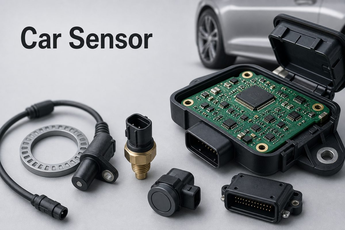
A car sensor detects a physical condition—such as temperature, pressure, speed, position, gas concentration, or distance—and converts it into an electrical signal that a vehicle controller can use. Modern vehicles depend on these signals for engine control, braking, safety, battery management, driver assistance, and comfort functions.
The sensing element is only one part of the system. Signal conditioning, power protection, connectors, PCB layout, software plausibility checks, and environmental validation all affect whether the data remains accurate inside a vehicle.
What Is a Car Sensor?
A car sensor is a transducer or electronic module that measures a vehicle condition and sends usable data to an electronic control unit (ECU). Depending on the sensor, the output may be an analog voltage, resistance change, frequency, pulse train, current signal, or digital message.
The ECU does not act on a raw physical quantity. It receives an electrical representation of that quantity, checks whether the value is plausible, and then uses it in a control or warning function. For example, a wheel-speed sensor supplies rotational information to the anti-lock braking system, while a coolant-temperature sensor helps the engine controller manage warm-up and over-temperature protection.
Car Sensors List
The most useful car sensors list groups devices by what they measure and which vehicle system uses the result. The table below is a practical list of car sensors and their functions rather than an exhaustive catalog of every model-specific device.
| Sensor | Measured Condition | Main Function | Typical Area |
| Oxygen sensor | Oxygen in exhaust gas | Supports air-fuel and emissions control | Exhaust system |
| Mass air flow sensor | Incoming air mass | Helps calculate fuel delivery | Air-intake path |
| MAP sensor | Intake-manifold pressure | Supports engine-load calculation | Intake manifold or ECU module |
| Coolant-temperature sensor | Engine coolant temperature | Supports warm-up, fan, and protection logic | Engine coolant passage |
| Crankshaft or camshaft sensor | Shaft position and speed | Provides timing reference | Near the crankshaft or camshaft target |
| Wheel-speed sensor | Individual wheel rotation | Supports ABS and stability control | Wheel hub |
| TPMS sensor | Tire pressure and often temperature | Warns about underinflation | Inside the wheel |
| Steering-angle sensor | Steering-wheel angle and rate | Supports stability and driver-assistance functions | Steering column |
| Parking ultrasonic sensor | Short-range obstacle distance | Supports parking warnings | Front or rear bumper |
| Radar or camera sensor | Objects, lanes, and relative motion | Supports ADAS functions | Grille, bumper, windshield, or mirrors |
| Battery current sensor | Battery current, voltage, and sometimes temperature | Supports battery and energy management | Battery terminal or pack |
Actual sensor count and placement vary by vehicle architecture, powertrain, trim level, and driver-assistance package. A hybrid or electric vehicle adds current, voltage, isolation, temperature, and position sensing that may not appear in a basic combustion-engine model.
How Do Car Sensors Work with an ECU?
Car sensors work by converting a physical input into an electrical signal, conditioning that signal, and delivering it to a controller that makes a decision. A typical signal path contains five stages:
- Sensing: A thermistor, Hall element, MEMS structure, piezoelectric element, photodiode, electrochemical cell, or antenna responds to the measured condition.
- Signal conditioning: The circuit amplifies, filters, linearizes, or converts the raw output.
- Conversion: An ADC, timer, comparator, or sensor ASIC creates data the controller can read.
- Communication: The value travels through a dedicated wire, PWM or frequency output, SENT, LIN, CAN, or another interface.
- Control: The ECU checks range and plausibility, compares related inputs, stores a diagnostic code when necessary, and adjusts the vehicle system.

A signal can be electrically valid yet physically wrong. For that reason, vehicle software often compares the sensor with operating context or another measurement. A throttle signal that moves outside its permitted relationship with a second channel, for example, may trigger a fault even if neither wire is fully open.
Car Sensors and Their Locations
Car sensors and their locations follow the physical condition being measured, but each location also creates a different reliability challenge. Under-hood sensors face heat, fluids, vibration, and electrical transients. Wheel-area sensors face water, road debris, connector movement, and electromagnetic noise. Cabin sensors have a milder environment but may need compact packaging, low standby current, and clean cosmetic integration.
- Engine and exhaust: oxygen, MAP, MAF, knock, crankshaft, camshaft, pressure, and temperature sensors.
- Wheels and chassis: wheel speed, tire pressure, ride height, acceleration, yaw, and brake-pressure sensors.
- Battery and power electronics: current, voltage, temperature, position, and isolation-monitoring circuits.
- Vehicle exterior: ultrasonic, radar, camera, rain, light, and ambient-temperature sensors.
- Cabin: occupant, seat-position, humidity, temperature, air-quality, touch, and gesture sensors.
Location affects more than the enclosure. It changes connector choice, coating strategy, grounding, heat flow, component grade, mechanical support, and the test profile expected for the finished module.
What Is a Common Car Sensor Problem?
A common car sensor problem is not always a failed sensing element. Wiring damage, connector corrosion, poor grounding, contamination, power-supply disturbance, mechanical misalignment, and PCB solder faults can produce the same symptoms as a defective sensor.
| Problem Area | Likely Effect | Useful Check |
| Open wire or loose connector | Missing, fixed, or intermittent reading | Connector inspection and continuity test |
| Short to ground or supply | Reading pinned outside the normal range | Voltage and resistance checks against service data |
| Contamination or blocked sensing path | Slow or biased response | Visual inspection and application-approved cleaning |
| Ground offset or electrical noise | Unstable data or faults under load | Oscilloscope check at the sensor and ECU reference points |
| PCB solder or via defect | Temperature- or vibration-dependent intermittency | Magnified inspection, controlled stimulation, and electrical test |
| Mechanical misalignment | Weak, irregular, or missing position signal | Air-gap, target, mounting, and runout check |
Replacing a sensor before checking the circuit can waste time and money. Diagnostic trouble codes identify the circuit or condition detected by the controller; they do not always prove which physical part has failed.
How Can You Tell If a Car Sensor Is Bad?
You can tell whether a sensor is likely faulty by combining diagnostic codes, live data, circuit checks, and operating symptoms. No single dashboard warning proves the diagnosis.
- Read stored, pending, and history diagnostic trouble codes.
- Compare live data with operating conditions and a known-good reference.
- Inspect the harness, terminals, seals, ground points, and supply voltage.
- Check whether the signal changes smoothly through the expected operating range.
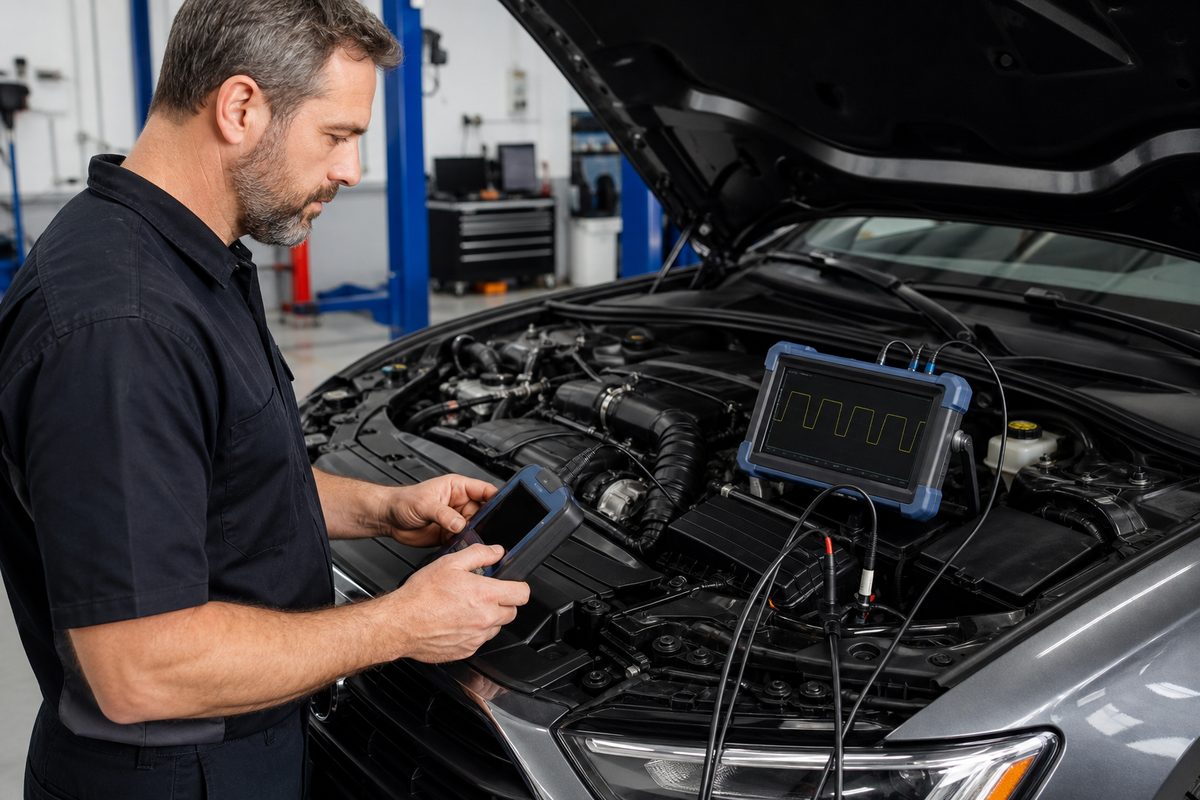
- Use an oscilloscope for speed, position, PWM, SENT, or intermittent signals that a multimeter may average out.
- Confirm mechanical alignment, air gap, contamination, leaks, or blocked passages when relevant.
Stop and use the vehicle maker’s service procedure when a sensor is part of braking, steering, airbags, high-voltage battery protection, or another safety-related system. Correct installation may also require calibration or a scan-tool routine.
How Are Car Sensor Problems Diagnosed?
Car sensor diagnosis should move from system evidence to circuit evidence before part replacement. A practical sequence is:
- Record the customer symptom, environmental condition, and freeze-frame data.
- Check related codes and technical service information.
- Inspect connectors, routing, shields, grounds, mounting, and the sensing surface.
- Verify power and reference voltage under load, not only with the connector unplugged.
- Measure the signal at the sensor and, when practical, at the receiving controller.
- Compare related sensors and determine whether the fault follows heat, vibration, moisture, or electrical load.
- Repair the circuit or replace the confirmed faulty part, then clear codes and verify the complete drive or calibration cycle.
Sensor cleaner, contact cleaner, and brake cleaner are not interchangeable. A product that is safe for one sensing element, coating, seal, or connector may damage another. Follow the component or vehicle service instructions instead of choosing a solvent by name alone.
What Does a Car Sensor PCB Contain?
A car sensor PCB may contain much more than the sensing element. The exact circuit depends on whether the module measures a slow analog variable, high-speed position, wheel rotation, current, pressure, image data, ultrasonic distance, or radar reflections.
Typical functional blocks include:
- input protection against reverse polarity, ESD, surge, and vehicle-line transients;
- voltage regulation and local decoupling;
- an analog front end with amplification and filtering;
- a sensor ASIC, ADC, microcontroller, or digital signal processor;
- clock, memory, calibration storage, and diagnostic functions;
- LIN, CAN, SENT, PSI5, PWM, frequency, or direct analog output circuitry;
- test points, programming access, connectors, and grounding structures.
Our related guide to custom PCB design for sensors explains signal, power, and test checks in more detail. Temperature-measurement projects can also use the dedicated temperature sensor PCB design guide.
Which PCB Design Choices Protect Automotive Sensor Signals?
Automotive sensor signals are protected by controlling the current return path, power entry, grounding, filtering, placement, thermal exposure, and mechanical stress as one system. Adding a filter late in the layout cannot fully correct a poor return path or a noisy power architecture.
- Place protection at the connector: Keep transient and ESD current paths short and away from sensitive analog nodes.
- Separate noisy and sensitive circuits: Switch-mode power, clocks, communication edges, and actuator currents should not share uncontrolled return paths with low-level sensor inputs.
- Control reference integrity: Ratiometric sensors depend on stable supply and reference relationships; voltage drop and ground offset can become measurement error.
- Filter for the real bandwidth: Remove noise without slowing the signal below the control system’s response requirement.
- Support connectors and heavy parts: Vibration and installation force can stress solder joints, copper, and plated holes.
- Plan coating and cleanliness: Flux residue, moisture, contamination, and coating under connectors or sensing surfaces can change leakage and sensor behavior.
- Provide test access: Include accessible points for power, ground, communication, analog output, programming, and production fixtures.
At board level, EMC performance depends on component selection, schematic design, placement, routing, stackup, and enclosure strategy. For radar, camera, and other high-frequency modules, controlled geometry and equalized paths may also be part of the sensor function, not merely interconnect.
How Are Automotive Sensor PCBs Tested?
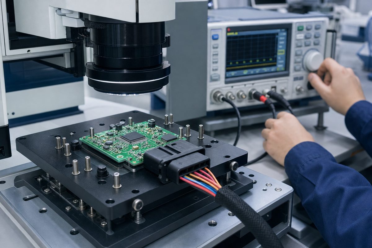
Automotive sensor PCBs are tested in layers: bare-board integrity, assembly quality, electrical function, calibration, and application-specific environmental or EMC validation. The required evidence must be defined by the customer and vehicle program.
- Bare PCB: electrical continuity/isolation, dimensional checks, hole and surface inspection, and applicable coupon measurements.
- PCBA: SPI where used, AOI, X-ray for hidden joints when justified, polarity and component verification, and workmanship inspection.
- Electrical test: supply current, reference voltage, communication, output range, diagnostics, and programming.
- Sensor function: stimulus-response testing, calibration, linearity, offset, sensitivity, and plausibility behavior as defined by the product specification.
- Reliability validation: temperature, vibration, humidity, chemical exposure, ingress, ESD, transient, emissions, and immunity tests selected for the mounting location and program requirements.
AEC-Q100, AEC-Q101, and AEC-Q200 address qualification of ICs, discrete semiconductors, and passive components. They do not by themselves certify a complete PCB assembly or sensor module. Module programs may also reference ISO 16750 environmental/electrical conditions, ISO 7637 vehicle-line transients, ISO 10605 ESD, and CISPR 25 emissions, but the exact editions, classes, test levels, and acceptance criteria must come from the customer specification.
For a broader comparison of inspection methods, see our PCB testing guide. Buyers preparing a production project can also review the questions in our automotive PCB manufacturer guide.
FAQ About Car Sensors
How many sensors are in a car?
There is no universal count. The number changes with vehicle age, powertrain, trim, safety package, and driver-assistance features. A basic car may use dozens, while a premium EV or ADAS-equipped vehicle can use many more sensing channels and integrated sensor modules.
Can a bad sensor stop a car from starting?
Yes. A missing crankshaft or camshaft position signal, an immobilizer-related input, or another critical fault can prevent starting. However, wiring, power, ground, connectors, and the receiving controller can create the same symptom, so the sensor should be tested before replacement.
What happens when a car sensor goes bad?
The controller may substitute a default value, limit performance, illuminate a warning, store a diagnostic code, disable a feature, or stop the system when safe operation cannot be confirmed. The response depends on the sensor and whether the function is safety-related.
Can a car sensor fail intermittently?
Yes. Heat, vibration, moisture, terminal movement, cracked solder joints, worn wiring, or marginal power can make a signal fail only under certain conditions. Recording live data and reproducing the environment is often more useful than testing the part cold on a bench.
Can you clean every car sensor?
No. Some exposed sensing elements can be cleaned only with a specified product and method; others should not be touched. The wrong solvent can damage coatings, plastics, seals, adhesives, or the sensing element. Follow the vehicle or sensor manufacturer’s procedure.
Does a diagnostic trouble code identify the bad part?
Not necessarily. A trouble code identifies the condition or circuit detected by the ECU. The root cause may be the sensor, harness, connector, supply, ground, mechanical system, contamination, or controller input. Diagnosis should confirm the circuit before replacement.
What is the difference between an analog and digital car sensor?
An analog sensor sends a continuously varying electrical value, while a digital sensor sends pulses or encoded data. Digital communication can add diagnostics and noise tolerance, but it still depends on correct power, grounding, timing, wiring, and interface design.
Why do automotive sensor PCBs need transient protection?
Vehicle supply and external wiring can expose electronics to reverse connection, ESD, switching noise, jump-start conditions, and transient pulses. Protection components and PCB current paths must work together so the disturbance is diverted without corrupting or damaging sensitive circuitry.
Does using AEC-qualified parts make a sensor module automotive-qualified?
No. AEC qualification is component-level evidence. The assembled module still needs design verification, manufacturing controls, software checks, calibration, environmental testing, EMC evaluation, and customer-specific approval appropriate to its vehicle location and function.
What files are needed to quote a car sensor PCB or PCBA?
Provide Gerber or ODB++ data, stackup requirements, BOM, CPL/pick-and-place file, assembly drawings, schematic when available, quantities, component-grade requirements, coating or potting notes, test specifications, programming files, acceptance criteria, and required production documentation.
How Can EBest Circuit Support an Automotive Sensor PCB Project?
A reliable car sensor module needs the PCB, assembly process, protection circuit, test access, and documentation to support the same electrical and environmental goal. At EBest Circuit, we review automotive sensor PCB and PCBA files from a manufacturing perspective, including stackup, material, component placement, connector stress, test access, BOM/CPL consistency, inspection scope, and production readiness.
Send your Gerber or ODB++ files, BOM, CPL, quantities, sensor interface, operating environment, and test requirements to sales@bestpcbs.com. Our team can review the project scope and prepare a PCB or PCBA quotation without treating unconfirmed automotive requirements as automatic approvals.







