A near-field probe helps find where a PCB generates RF noise. It cannot tell you by itself which part of the product radiates enough to fail an emissions test. Start with the troublesome frequency, find the same signature on the board and on the cables, then repeat the system measurement after one controlled change.
EMI Troubleshooting
Write down the failure frequency and the exact operating mode before scanning. In this hypothetical example, a 72 MHz peak is present in a repeatable emissions setup while a controller is under load. The regulator switches at about 2 MHz, so the peak could be its 36th harmonic. That arithmetic suggests where to look, but another circuit can generate the same frequency.
Capture the product off and on, then document the supply, load, enclosure and cable routing. If the peak is present with the unit off, investigate the ambient signal before trying to fix the board.
Near-Field Probes
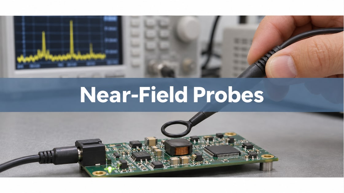
Choose the probe for the question. An H-field loop locates magnetic coupling associated with high-frequency current paths. An E-field probe helps find areas with rapidly changing voltage. A clamp-on RF current probe is a separate tool for tracing current on a cable.
| Tool | What to look for | Keep fixed in A/B |
| H-field loop | Current-related board hot spots | Loop angle and height |
| E-field probe | Strong electric-field regions | Tip distance and position |
| RF current clamp | Cable current at suspect frequency | Cable routing and clamp location |
The largest displayed reading from one probe is not directly comparable with a reading from another probe. Their responses and coupling differ.
Near-Field H Field Probe
Use a larger H-field loop for the first sweep and a smaller one to separate nearby candidates. Rotate the loop and compare at a consistent height. A null at one angle does not show that the circuit is quiet; it can just mean the magnetic field is not passing through the loop.
Once you find a repeatable peak, mark the probe point and use a nonconductive support to keep its height and angle fixed. Use noncontact scanning in a safe setup; do not touch energized conductors or defeat guards.
Near-Field Probe Spectrum Analyzer
Set a span wide enough to recognize the harmonic family, then narrow the display around the failure frequency. Record the center and span, resolution bandwidth, detector, attenuation, gain and cable. Keep these settings identical for before-and-after traces. Changes to the analyzer can look like changes to the product.
If a preamplifier improves sensitivity, also check overload. An apparent peak that disappears when input attenuation is increased may be an instrument artifact. Keep a baseline with the probe in its final position before testing any change.
Switching Regulator EMI
Correlate the peak with the regulator by using an approved operating-mode change. If the fundamental moves from 2.00 MHz to 1.95 MHz in the example, its 36th harmonic moves from 72.0 MHz to 70.2 MHz. A matching shift at the board and in the repeatable system measurement is stronger evidence than one matching frequency.
Hold the board revision and all other settings fixed when possible. If the frequency cannot be changed, compare valid load or enable states and record what else changes with them. A regulator shutoff that also stops the rest of the board cannot isolate the regulator by itself.
Common Mode Current Probe
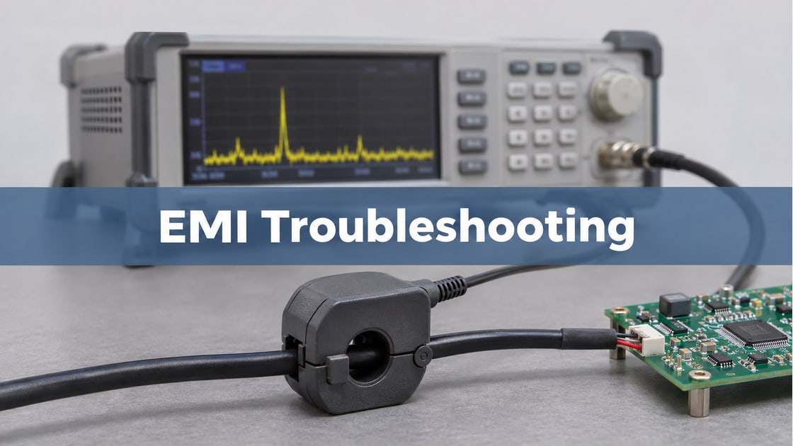
Clamp around the complete cable bundle to look for net common-mode current. With a forward and return conductor inside the same aperture, equal and opposite currents ideally cancel. Clamping only one conductor measures a different quantity and can make normal differential current look like the suspected path.
Check multiple repeatable positions and then mark the one used for comparison. Keep the cable length and route fixed. Apply one approved reversible path change and check whether both the cable-current peak and the system peak move. For absolute current, use the probe’s transfer impedance and calibration; relative comparison can use a fixed setup.
Near-Field vs Far Field
A near-field scan identifies local sources and coupling clues; a radiated test measures the complete product at a defined antenna geometry. The strongest local source may be well contained, while a smaller one couples effectively onto a cable or enclosure seam.
| Observation | Next step |
| Board peak only | Check other sources and coupling paths |
| Board and cable peaks track | Test one reversible cable-path change |
| Cable peak drops but system does not | Check other cables, seams or the setup |
| All three track | Repeat the fix in the final configuration |
If a seam becomes the likely path, consult the board-level shielding guide. Do not select a new shield solely because the probe reading above the circuit is high.
EMI Pre-Compliance Testing
Use a bench comparison to decide whether a change deserves a formal retest. Repeat the original setup with the final enclosure, representative harness and required operating modes. Record baseline and changed traces and repeat the comparison to distinguish the change from normal setup scatter.
A drop at the fixed probe is not the release criterion. Use the applicable radiated or conducted test, detector, geometry and product limit for acceptance. Retain the configuration and evidence so the production revision can be checked against the design that passed.
Frequently Asked Questions
Can I use a near-field probe with an oscilloscope instead of an analyzer?
Yes, if its bandwidth, sensitivity and available frequency-domain tools suit the signal. Some scopes help correlate a spectrum with time-domain activity. Check the probe and input termination, avoid overload and keep acquisition settings fixed. A scope trace at the bench is not a regulatory measurement.
Why is the probe reading much higher when I tilt it?
The loop responds to magnetic flux through its area, which changes with orientation. Tilting can also alter the distance from the board. Scan several angles to locate a source, but fix the angle and height when you compare baseline and modified hardware.
Is the strongest near-field peak always the emission failure?
No. Radiation depends on the source, coupling path and structure that radiates. A strong local field may never reach the antenna efficiently. Compare the failure frequency and changes at the board, cable and system levels before choosing which component or layout to modify.
What if the spectrum changes when I move the cable?
Cable placement may change coupling or radiation, which is useful evidence but also a source of measurement variation. Mark the baseline route and clamp position, then repeat one deliberate routing change. Do not compare two board revisions with different cable positions and attribute the entire difference to the PCB.
Do I need a calibrated probe to compare two revisions?
A fixed relative comparison can be useful without absolute calibration if the probe, geometry, gain and operating conditions remain unchanged. Calibration and specified corrections matter when reporting absolute field or cable current. Record the setup so another engineer can reproduce the comparison.
Can I try a clip-on ferrite during the diagnosis?
A suitable temporary ferrite can help test whether cable common-mode current contributes, when used safely within the approved bench setup. Its behavior depends on material, frequency and placement. Compare cable and system results before considering a permanent filter, and revalidate the final design.
How can I distinguish a clock harmonic from a switching harmonic?
List their fundamentals and expected multiples, then vary one approved mode at a time. Look for the corresponding frequency shift or a time-domain correlation. If the candidates overlap and cannot be varied independently, treat the attribution as unresolved and take another measurement rather than naming a source.
Does an EMI pre-compliance improvement prove the board now passes?
No. A repeatable bench reduction supports the decision to retest. Final acceptance depends on the applicable method, limits, operating modes, enclosure and harness configuration. A local probe or quick bench antenna measurement cannot substitute for the required whole-product test under the specified conditions.
References
- SIGLENT: Troubleshooting With Near-Field and Current Probes
- Rohde & Schwarz: EMI Debugging a Switched-Mode Power Supply
Discuss Your PCB Requirements
For a Best Technology PCB fabrication review, send your stackup, copper layout and the suspected coupling region to sales@bestpcbs.com. Include the test configuration and failure frequency so the drawing review addresses the right part of the board.