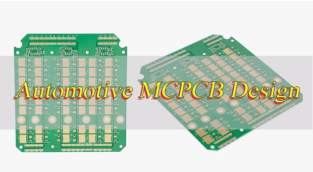
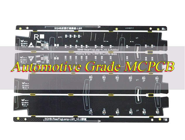
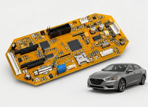
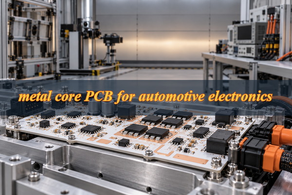
Metal core PCB for automotive electronics is commonly used in LED headlights, daytime running lights, and selected power control modules where concentrated heat must be transferred to a vehicle housing or heat sink. Compared with conventional FR4, metal-backed PCBs offer an effective way to manage heat in compact automotive assemblies.
However, thermal conductivity alone does not guarantee reliable performance. Dielectric insulation, component placement, mounting conditions, and manufacturing consistency determine how well an MCPCB performs under automotive operating conditions. Selecting the right materials and validating the complete assembly can prevent overheating, insulation failures, and costly production changes.
Which Automotive Electronics Applications Benefit Most from Metal Core PCBs?
Metal core PCBs are particularly suitable for automotive lighting and selected power electronics with concentrated heat sources. Common applications include:
- LED Headlights: Transfer heat from high-power LED arrays to the headlamp heat sink, helping maintain acceptable junction temperatures in compact housings.
- Daytime Running Lights (DRLs): Improve heat transfer during continuous LED operation, particularly where airflow and installation space are limited.
- Brake and Tail Lights: Spread heat generated by LED clusters, reducing localized temperature buildup in enclosed lighting modules.
- Automotive Infrared Illumination: Manage heat from high-output IR LEDs used in selected driver monitoring and sensing systems.
- Auxiliary Power Converters: Provide a thermal path for MOSFETs, rectifiers, and voltage regulators when the circuit and mounting structure suit a metal-backed substrate.
- Motor Driver Modules: Help transfer heat from power transistors into a motor housing or external cooling structure.
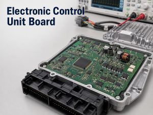
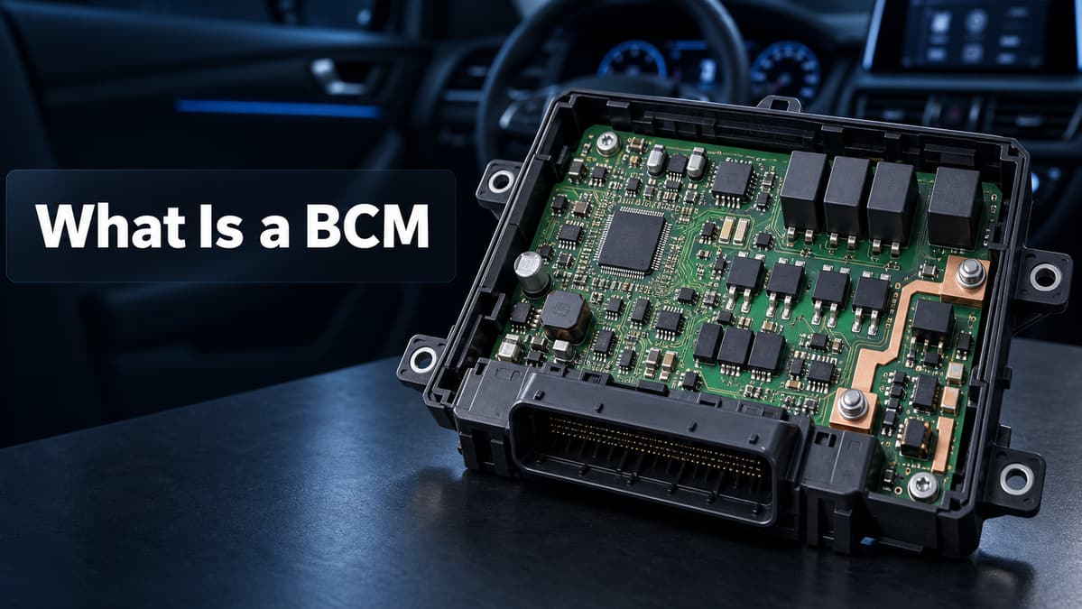
Not every automotive electronic system benefits from a metal core PCB. Complex ECUs, BMS control boards, and ADAS processors often use multilayer FR4 or specialized substrates to accommodate dense circuitry and high-speed signals.
Metal Core PCB vs. FR4 vs. Ceramic PCB: Which Is Right for Automotive Electronics?
The choice between metal core PCB, FR4, and ceramic PCB depends on heat load, circuit complexity, electrical isolation, mounting requirements, and manufacturing cost.
| Comparison | Metal Core PCB | FR4 PCB | Ceramic PCB |
|---|---|---|---|
| Thermal performance | Metal base spreads heat toward a cooling surface | Lower through-thickness thermal conductivity; additional thermal structures may be required | High thermal conductivity with suitable ceramic materials |
| Electrical insulation | Provided by the dielectric layer | Provided by resin-glass laminate | Common ceramic substrates are electrically insulating |
| Circuit complexity | Conventional IMS favors simpler routing; specialized multilayer options available | Suitable for complex multilayer routing | Depends on ceramic manufacturing technology |
| Weight | Aluminum is relatively light; copper is heavier | Generally lightweight | Depends on material and construction |
| Mechanical properties | Rigid metal-backed structure | Versatile mechanical characteristics | Hard and dimensionally stable but brittle |
| Cost | Moderate for conventional aluminum IMS | Generally economical for standard designs | Often higher for specialized structures |
| Typical applications | Automotive lighting and selected power modules | ECU, BMS control, infotainment | Specialized power modules and semiconductor packaging |
| Main limitation | Dielectric thermal resistance and routing restrictions | Heat removal from concentrated power devices | Brittleness and manufacturing complexity |
What Are the Key Design Requirements for Automotive Metal Core PCBs?
Automotive metal core PCB design begins with the conditions the finished module will face in service. Operating temperature, power dissipation, electrical isolation, and mechanical installation directly affect material selection and PCB construction.
The main design requirements include:
- Operating Temperature: Define minimum and maximum ambient temperatures, expected enclosure temperature, and operating duty cycle.
- Power Dissipation: Calculate the heat produced by LEDs, MOSFETs, regulators, and other power components under maximum operating loads.
- Electrical Isolation: Specify working voltage, dielectric withstand requirements, creepage, clearance, and grounding arrangements.
- Current Capacity: Determine conductor dimensions and copper thickness based on current loading and allowable temperature rise.
- Mechanical Installation: Confirm PCB dimensions, mounting holes, flatness, fastening positions, and heat-sink contact requirements.
- Environmental Conditions: Account for temperature cycling, vibration, humidity, contamination, and other service conditions.
An LED headlight inside a sealed housing, for example, may operate at a much higher temperature than the surrounding air. A PCB designed using only room-temperature measurements can underestimate the thermal stress experienced during vehicle operation.
Worst-case operating conditions should govern the final design, particularly when power devices have limited junction-temperature margins.
How Do You Select the Right Metal Core PCB Materials and Stackup?
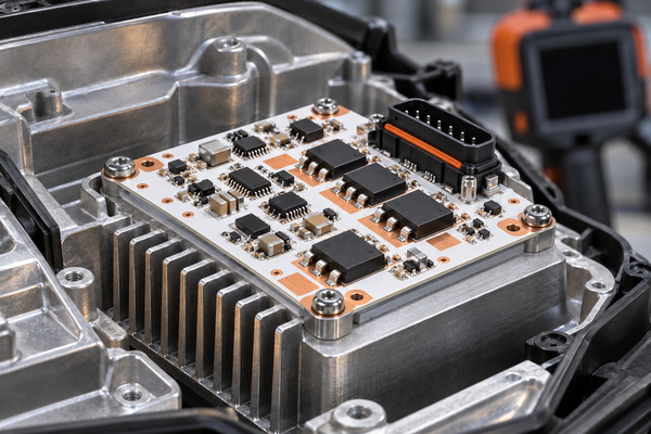
An automotive metal core PCB typically consists of copper circuitry, a thermally conductive dielectric layer, and an aluminum or copper base. The copper carries electrical current, the dielectric provides insulation, and the metal base spreads heat toward the cooling structure.
Aluminum is widely used in automotive lighting because it offers useful heat spreading with relatively low weight and cost. Copper has higher bulk thermal conductivity but adds weight and expense, making it more suitable where its additional thermal performance is justified.
| Design Parameter | Selection Consideration | Verification |
|---|---|---|
| Metal base | Aluminum for weight and cost balance; copper where higher conductivity offers an advantage | Material grade, thickness and housing compatibility |
| Dielectric conductivity | Higher conductivity can reduce resistance through the insulating layer | Material datasheet and thermal properties |
| Dielectric thickness | Thinner layers reduce thermal resistance but may affect insulation margins | Thickness, dielectric withstand and aging performance |
| Copper thickness | Depends on current, conductor geometry and temperature rise | Current-capacity calculation and fabrication limits |
| Base thickness | Affects stiffness, weight, machining and mounting compatibility | Mechanical drawing and installation requirements |
| Surface finish | ENIG, lead-free HASL or OSP based on assembly requirements | Solderability, component compatibility and planarity |
| Stackup structure | Single-sided IMS or specialized multilayer construction | Routing, isolation and manufacturing feasibility |
The dielectric is often the most critical material choice. A material with 2.0 W/m·K thermal conductivity can provide useful heat transfer, but its resistance also depends on thickness and effective heat-transfer area.
The insulation system must retain suitable electrical and mechanical properties under the specified automotive environment. Thermal conductivity, dielectric strength, aging resistance, and processing compatibility should be evaluated together.
How Do You Calculate and Optimize Thermal Performance in Automotive MCPCB Design?
Automotive MCPCB thermal performance depends on the entire path from the component junction to the surrounding environment. Heat passes through the component package, solder connection, copper circuitry, dielectric layer, metal base, thermal interface material, and heat sink or housing.
The maximum allowable junction-to-ambient thermal resistance can be estimated using:
RθJA,max = (TJ,max − TA) / P
Where:
- TJ,max: Maximum permitted junction temperature
- TA: Ambient temperature
- P: Component power dissipation
- RθJA,max: Maximum allowable junction-to-ambient thermal resistance
Consider a power device dissipating 8 W at an ambient temperature of 85°C, with a selected junction-temperature design limit of 125°C.
The allowable thermal resistance is:
RθJA,max = (125 − 85) / 8 = 5°C/W
The complete assembly must therefore maintain an effective thermal resistance of 5°C/W or less under these assumed conditions.
The dielectric layer contributes to this resistance. Its idealized through-thickness resistance can be estimated as:
Rθ = t / (k × A)
Here, t is dielectric thickness, k is thermal conductivity, and A is the effective heat-transfer area.
For a 100 µm dielectric, 2 W/m·K conductivity, and an assumed heat-transfer area of 100 mm², the calculated resistance is 0.5°C/W. This excludes spreading resistance, contact resistance, and other heat-transfer losses.
Thermal improvements should concentrate on:
- Component Placement: Position high-power devices where heat can reach the cooling surface through a short thermal path.
- Copper Distribution: Provide sufficient conductor area for current handling and heat spreading.
- Dielectric Selection: Balance thermal conductivity, layer thickness, and electrical insulation.
- Thermal Interface: Control mounting pressure, board flatness, and thermal interface material thickness.
- Temperature Verification: Measure component and PCB temperatures under representative power loads and enclosure conditions.
For assemblies containing several power devices, simultaneous heat generation must be included in the thermal assessment. A calculation establishes the initial target, while measurements on the assembled module confirm whether that target has been met.
How Can You Prevent Common Automotive Metal Core PCB Design and Assembly Failures?
Automotive MCPCB failures often develop around solder joints, dielectric interfaces, and mechanical mounting points. Repeated temperature changes produce expansion differences between materials, while vibration and mounting stress can damage electrical connections over time.
Common failure risks include:
- Solder Joint Cracking: Thermal expansion mismatch and vibration can fatigue solder joints. Suitable pad geometry, component support, and mounting arrangements help reduce mechanical stress.
- Dielectric Breakdown: Insufficient insulation margins, material defects, or machining damage can compromise electrical isolation. Proper dielectric selection and clearance control are essential.
- Delamination: Excessive thermal stress or incompatible materials can weaken bonded layers. Qualified laminates and controlled fabrication conditions reduce this risk.
- Board Deformation: Uneven fastening pressure can distort the assembly or reduce contact with the heat sink. Mounting-hole placement and board flatness require attention.
- Solder Voiding: Inappropriate solder paste deposition or reflow conditions can weaken solder connections. Stencil design and soldering profiles should be validated for the actual substrate.
- Moisture-Related Leakage: Contamination and environmental exposure can reduce insulation resistance. Cleanliness controls and suitable protective materials help maintain electrical performance.
Mounting details are particularly important in metal-backed assemblies. Exposed metal edges and fasteners must not create unintended electrical paths, while excessive clamping force can damage solder joints or compromise the thermal interface.
How Are Automotive Metal Core PCBs Manufactured and Assembled?
Automotive metal core PCB production involves PCB fabrication and component assembly. Both stages require controlled processing to maintain electrical insulation, thermal performance, and dimensional accuracy.
PCB Manufacturing Process
- Material Preparation: Inspect the aluminum or copper-backed laminate, dielectric layer, and copper foil to confirm material specifications, thickness, and surface condition.
- Circuit Patterning and Etching: Form copper circuits through imaging and chemical etching while maintaining conductor dimensions, spacing, and dielectric integrity.
- Solder Mask and Surface Finishing: Apply the specified solder mask and surface finish, such as ENIG or lead-free HASL, to protect exposed circuitry and provide solderable surfaces.
- Mechanical Processing: Produce the board outline, mounting holes, and required cutouts. Control metal burrs, dimensional tolerances, and insulation clearance around exposed edges.
- Bare PCB Inspection: Perform electrical testing, dimensional checks, and visual inspection to verify circuit integrity and fabrication quality.
PCB Assembly Process
- Solder Paste Printing: Apply solder paste to component pads using a suitable stencil, controlling deposition volume and alignment.
- Component Placement: Mount LEDs, MOSFETs, resistors, and other components according to the approved BOM and placement data.
- Reflow Soldering: Use a validated temperature profile that accounts for the metal substrate’s thermal characteristics and component soldering requirements.
- Assembly Inspection: Inspect component alignment and solder joints using AOI, visual inspection, and X-ray where appropriate.
- Functional and Thermal Testing: Verify electrical operation and, where required, measure component temperatures under defined power loads.
The finished PCB must also meet the mounting dimensions and contact requirements of the automotive housing, particularly when the metal base forms part of the assembly’s cooling path.
What Tests Verify Automotive Metal Core PCB Quality and Reliability?
Automotive metal core PCB testing covers electrical integrity, insulation performance, fabrication quality, and assembly reliability. Test requirements depend on the product specification and customer qualification plan.
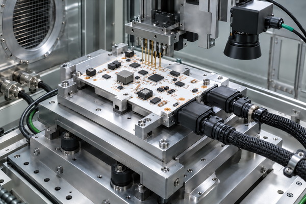
- Electrical Continuity Testing: Detect open circuits and unintended electrical connections in finished bare PCBs.
- Dielectric Withstand Testing: Verify that the insulation withstands the specified test voltage without electrical breakdown.
- Insulation Resistance Testing: Measure electrical leakage between isolated conductive structures under defined conditions.
- Dimensional and Visual Inspection: Check PCB thickness, mounting holes, edge quality, solder mask, and visible manufacturing defects.
- Solder Joint Inspection: Use AOI, visual inspection, or X-ray as appropriate to identify soldering defects and placement problems.
- Thermal Performance Testing: Measure LED or semiconductor temperatures under specified electrical loads and cooling conditions.
- Temperature Cycling Testing: Evaluate solder joint integrity, material interfaces, and insulation reliability after repeated temperature changes.
- Vibration Testing: Assess mechanical durability and electrical connection stability under the required automotive vibration profile.
- Functional Testing: Confirm that the assembled circuit meets its electrical and operating specifications.
PCB quality requirements may reference IPC-6012F, IPC-6012FA, and IPC-A-600, while assembly acceptance may follow IPC J-STD-001 and IPC-A-610. The applicable standards and acceptance criteria should be established for the project.
Temperature cycling, vibration, and other environmental qualification tests follow the customer’s approved test plan rather than being performed automatically on every production board.
How Do You Move Automotive Metal Core PCBs from Prototype to Volume Production?
Moving an automotive metal core PCB into volume production requires repeatable manufacturing results, not simply a larger order quantity. The approved design, materials, and inspection requirements must remain consistent as production increases.
Engineering Prototypes
Initial samples verify PCB dimensions, electrical isolation, component assembly, mounting fit, and thermal performance. Any design changes identified during testing are incorporated into controlled manufacturing revisions before the next build.
Pilot Production
A representative production run evaluates process stability. Particular attention is given to dielectric integrity, machining accuracy, solder joint quality, and inspection consistency. Problems discovered at this stage should be resolved before full production release.
Volume Production
Approved materials, manufacturing files, inspection criteria, and process requirements are maintained throughout production. Depending on customer requirements, automotive programs may involve APQP, PPAP, PFMEA, control plans, and production part approval documentation.
Material lot identification, inspection records, and revision control help maintain consistency between batches. Changes involving approved materials or manufacturing processes may require customer notification and additional validation.
Automotive Metal Core PCB Case Study: From Engineering Requirements to Production
Project Background
EBest Circuit manufactured an aluminum-based metal core PCB for an automotive LED headlamp application. The project required a compact board with effective heat transfer, electrical insulation, and a solderable surface suitable for the lighting assembly.
Requirements and Challenges
The customer specified a 1.5 mm board thickness, 3 oz copper, a 2.0 W/m·K thermal conductivity rating, white solder mask, ENIG surface finish, and 100% electrical testing. The main challenge was combining a metal-backed construction with relatively heavy copper circuitry while maintaining the required board dimensions and electrical isolation.
EBest Circuit Solution
EBest Circuit manufactured the aluminum-backed PCB with the specified copper thickness, insulation structure, solder mask, and surface finish. The 3 oz copper supported the required conductor construction, while ENIG provided a planar solderable finish for component assembly. White solder mask was selected for the lighting application, where visible-light reflection can be beneficial. Fabrication and inspection were arranged around the specified board structure and electrical testing requirements.
Project Results
The project was manufactured using the specified metal-backed construction, with 100% electrical testing included in the production requirements. The resulting PCB provided the required construction for the automotive lighting application, including heavy copper circuitry, a solderable surface, and an electrically insulated metal base.
How Should You Evaluate an Automotive Metal Core PCB Manufacturer?
A reliable automotive metal core PCB manufacturer should be able to demonstrate suitable manufacturing capabilities, controlled production processes, and relevant quality documentation.
Before selecting a supplier, engineering and purchasing teams should evaluate:
- Manufacturing Capability: Confirm available metal substrates, dielectric systems, copper thicknesses, PCB structures, and machining tolerances.
- Quality Certification: Verify ISO 9001 or IATF 16949 certificates, including certificate validity, the certified facility, and applicable scope.
- Material Traceability: Request laminate specifications, material identification, lot records, and relevant conformity documentation.
- Engineering Support: Check whether the manufacturer provides practical DFM feedback on electrical insulation, mounting features, material choices, and assembly limitations.
- Testing Capability: Confirm available electrical, dielectric, dimensional, and assembly inspection methods.
- Production Control: Evaluate revision management, process qualification, corrective actions, and customer approval procedures.
- Commercial Reliability: Compare quotation coverage, material availability, tooling costs, production lead time, and delivery conditions.
For automotive OEM and Tier 1 programs, supplier audits and customer-specific production approval requirements may also apply.
Why Choose EBest Circuit for Automotive Metal Core PCB Manufacturing?
EBest Circuit provides custom metal core PCB manufacturing and assembly services for automotive lighting and selected power electronics applications. Our China-based manufacturing operations support customers from engineering prototypes through repeat production.
Customers can benefit from:
- IATF 16949 and ISO 9001 Quality Management: Quality management certifications supporting controlled manufacturing and automotive project requirements. Relevant certification documentation can be provided for customer review.
- Free DFM Review: Engineering feedback on fabrication constraints, dielectric insulation, mounting features, material selection, and assembly feasibility before production.
- Custom Metal Core PCB Manufacturing: Aluminum and copper-based solutions with materials, copper thicknesses, surface finishes, and mechanical features selected according to project requirements.
- One-Stop PCB Fabrication and Assembly: Coordinated PCB manufacturing, component sourcing, SMT assembly, and applicable inspection services.
- Prototype and Volume Production: Support for engineering samples, pilot builds, and repeat manufacturing orders with controlled revisions.
- Engineering and Quality Support: Assistance with technical specifications, material documentation, manufacturing questions, and agreed inspection requirements.
For automotive electronics projects, a free DFM review can identify fabrication and assembly risks before tooling and production begin, helping customers avoid unnecessary revisions and delays.
FAQs About Metal Core PCB for Automotive Electronics
Q1: Is the aluminum base of an automotive MCPCB electrically grounded?
A1: Not automatically. The metal base is insulated from the circuit copper. Chassis grounding requires an intentional electrical connection through the approved mounting design.
Q2: Can automotive metal core PCBs support plated-through holes?
A2: Yes, with suitable specialized constructions. Conventional single-sided IMS has limitations, and holes passing through the metal base require proper electrical isolation.
Q3: Can components be mounted on both sides of a metal core PCB?
A3: Yes, depending on the construction. Standard single-sided IMS typically supports components on one side, while specialized multilayer structures can accommodate more complex assemblies.
Q4: Why is white solder mask used in automotive LED PCBs?
A4: White solder mask can improve visible-light reflection in LED modules. Reflectivity, thermal stability, and resistance to discoloration should guide material selection.
Q5: Can automotive MCPCBs use lead-free solder?
A5: Yes. Lead-free SMT assembly is possible with compatible materials and components. Reflow profiles must be validated because the metal substrate affects heating behavior.
Q6: Does a metal core PCB eliminate the need for a heat sink?
A6: Not necessarily. The metal base spreads heat, but high-power devices may still require an external heat sink or metal housing. Total thermal resistance determines cooling requirements.
Q7: Can conformal coating protect automotive MCPCBs from moisture?
A7: Yes. Suitable conformal coatings help protect assembled circuitry from moisture and contamination. Coating must not interfere with electrical contacts or thermal interfaces.
Q8: Are halogen-free MCPCB materials automatically RoHS compliant?
A8: No. Halogen-free specifications and RoHS requirements address different chemical restrictions. Separate compliance documentation may be required.
Q9: Can press-fit connectors be installed on automotive MCPCBs?
A9: Only when the PCB construction supports the required hole structure and insertion forces. Conventional IMS may not support standard press-fit connections without specialized construction.
Q10: What packaging protects automotive metal core PCBs during shipping?
A10: Protective trays, separators, and suitable cushioning help prevent surface damage, edge defects, and component damage. Packaging and lot identification should match the customer’s requirements.
How Can You Get a Custom Automotive Metal Core PCB Quote?
EBest Circuit provides custom metal core PCB fabrication and optional assembly services for automotive electronics projects. Quotations are based on the board construction, technical requirements, testing scope, and order quantity.
For an accurate quotation, please provide:
- PCB Files: Gerber data, drill files, mechanical drawings, and stackup requirements.
- Material Specifications: Aluminum or copper base, dielectric properties, copper thickness, board thickness, and surface finish.
- Operating Requirements: Power dissipation, temperature range, electrical isolation, mounting conditions, and applicable automotive standards.
- Assembly Information: BOM, component placement files, assembly drawings, and required testing.
- Order Details: Quantity, required delivery date, and delivery location.
- Quality Requirements: Inspection criteria, traceability expectations, and customer-specific approval documentation.
Planning a metal core PCB for automotive electronics project? Whether you are developing prototypes or preparing for volume production, EBest Circuit can help you review material specifications, verify manufacturing feasibility, and coordinate PCB fabrication and assembly. Send your project files and requirements to sales@bestpcbs.com for a free DFM review, engineering support, and a custom quotation.