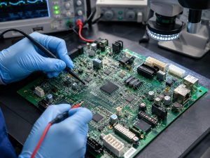
Audio PCB assembly must do more than produce boards that power on. A finished audio PCBA should deliver consistent gain, noise level, frequency response, channel balance and output behavior across every unit. Component tolerances, substitute parts, solder quality, grounding and thermal conditions can all influence the electrical performance that eventually reaches the listener.
EBest Circuit (Best Technology) supports PCB fabrication, component sourcing, assembly and functional testing for audio products moving from prototype validation into repeat production. With more than 20 years of PCB and PCBA manufacturing experience, we help customers identify sourcing, assembly and test risks before they become recurring production problems. For an upcoming project, send your BOM and available production files to sales@bestpcbs.com.
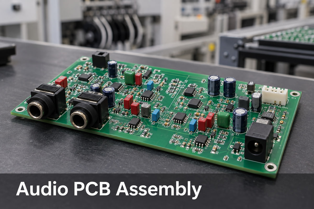
Audio PCB Assembly Diagram: Where Signal, Power, Grounding and Assembly Meet
An audio PCB normally combines a signal path, power network and grounding structure. An assembly defect in any one of these areas can change the final audio result.
Typical signal path:
Input → preamplifier → filter or ADC → codec or DSP → DAC or output driver → power amplifier → output
Supporting power path:
Power input → regulation and filtering → analog rail, digital rail and amplifier rail
Grounding path:
Signal ground → power return → shielding or chassis connection
These systems interact throughout the board. A wrong feedback resistor may change amplifier gain. A reversed capacitor can disturb a supply rail. Poor solder coverage under a power device can increase operating temperature, while contamination near a high-impedance input may increase leakage or noise.
Component placement also matters. Small resistors and capacitors around op-amps, codecs and filters often define gain, bias or cutoff frequency. The board may therefore power up normally while one channel still performs differently from the design target.
For repeat production, the assembly should follow one controlled data package containing the released Gerbers, BOM, pick-and-place file, assembly drawings, approved substitutions, firmware requirements and test limits. The schematic defines the intended circuit; this production package enables the factory to reproduce it.
How Audio Amplifier PCB Assembly Differs from Mixers and Musical Instruments
Audio amplifier PCB assembly is mainly concerned with current, heat and output stability, while mixers and musical instruments place greater emphasis on low-level signals, channel matching, controls and mixed analog/digital circuitry.
| Audio product | Main assembly concern | Key performance check |
|---|---|---|
| Power amplifier | High-current joints, thermal pads and large capacitors | DC offset, load stability and distortion |
| Mixer or audio interface | Multiple matched channels and dense connectors | Channel balance, crosstalk and noise |
| Musical instrument | Mixed analog/digital circuits and specialist ICs | Signal response, controls and unwanted noise |
| Microphone front end | High gain and sensitive inputs | Input noise, bias and gain accuracy |
A power amplifier may require controlled thermal-pad soldering, high-current connections and testing under a representative load. A mixer has a different risk: one incorrect resistor or capacitor may affect only one channel, so visual inspection alone cannot confirm that every channel performs the same.
Musical instruments and effects units may combine potentiometers, switches, displays, MIDI, USB and specialist audio ICs on the same assembly. Mechanical controls and electrical performance therefore need to be checked together.
Listening can expose obvious hum, pops or missing channels, but measurable limits provide a more repeatable production standard. Listening is best used as a complementary check when it reflects a meaningful product requirement.
How Can Hard-to-Source Audio ICs Be Secured for Production?
A hard-to-source audio IC should be secured before the production date is confirmed. If one unavailable codec, DSP, converter or specialist analog device can stop the entire build, its usable quantity—not SMT capacity—determines when production can begin.
First decide whether the IC is replaceable:
| Compatibility check | What must remain compatible |
|---|---|
| Hardware | Package, pinout, supply range and surrounding circuitry |
| Software | Registers, firmware and device initialization |
| Audio performance | Noise, distortion, gain, bandwidth and sound-generating behavior |
If a candidate cannot satisfy all three areas, the IC should remain locked to its exact manufacturer part number.
For the current production batch:
The required quantity can be secured through an authorized distributor, verified project inventory, customer-supplied stock or a controlled combination of these sources.
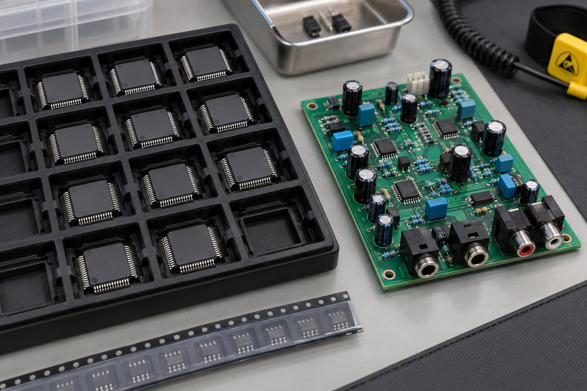
Customer-supplied ICs can be assembled together with factory-sourced standard components. However, the shipment should include enough usable devices to cover the order and normal production attrition. Providing exactly one IC for every finished board leaves no allowance for setup loss, placement damage or rework.
For repeat production:
The response should depend on the supply risk:
- A temporary shortage may justify reserving stock for the next scheduled batch.
- A confirmed end-of-life notice may require a last-time buy.
- Demand beyond the secured supply may require validation of an alternative or a controlled redesign.
The production plan is reliable only when the design-locked quantity is secured for the current batch and a separate supply strategy exists for future orders.
How Can Substitute Components Preserve Audio Performance?
A substitute should be approved according to the component’s role in the audio circuit. Parts that set gain, filtering, conversion or output behavior need particular attention because a substitution can change measured or perceived performance.
Different component roles require different checks:
| Component role | What must remain comparable | Possible audio effect |
|---|---|---|
| Filter or gain-setting resistors and capacitors | Value, tolerance and temperature behavior | Gain, cutoff frequency or channel balance |
| Signal-path capacitors | Capacitance, dielectric, ESR, voltage rating and polarity | Low-frequency response, noise or distortion |
| Op-amps and analog devices | Supply range, noise, bandwidth, distortion, output drive and stability | Noise floor, headroom, frequency response or oscillation |
| Codecs, ADCs, DACs and DSPs | Pinout, interface, firmware support and relevant audio specifications | Audio I/O failure or a change in measured performance |
Use the BOM to control the substitution level:
- General-purpose positions may list approved alternatives or minimum specifications.
- Audio-sensitive positions should name the parameters that must remain within limits.
- Firmware-dependent or product-defining devices should remain locked to an exact manufacturer part number.
A new alternative can be approved by the customer’s design team when its function and relevant performance are clearly equivalent. If the datasheets leave uncertainty about noise, distortion, stability or channel response, validate the part in a production-intent build before using it in volume production.
Record the approved part number in the controlled BOM and retain any supporting test results with the revision record. This gives purchasing a clear choice of parts while preserving the product’s sound and batch-to-batch consistency.
Why Should a Prototype Prove More Than “Power On”?
An audio PCBA prototype should confirm that the intended manufacturing process can reproduce the required audio performance, not simply that the board starts successfully.
A useful production-intent prototype should verify:
- footprints, polarity and assembly clearances;
- power rails, current draw and programming;
- controls and communication;
- relevant audio parameters such as gain, noise, channel balance or distortion.
This stage often reveals issues that do not appear during schematic review. A board may operate correctly but show increased noise because a regulator behaves differently under load. A connector may block access to a programming point. A large thermal pad may need a stencil adjustment to achieve consistent solder coverage.
Any correction should be returned to the controlled BOM, drawings, test method or production files before volume release. The prototype is therefore not just a smaller production order. Its real purpose is to remove uncertainty before more boards are built.
A known-good reference unit can help during later production, but numerical test limits should remain the primary acceptance standard wherever practical.
What Keeps Audio PCBA Consistent from One Production Batch to the Next?
Batch-to-batch consistency depends on controlling materials, revisions, manufacturing settings and test limits.
| Production control | What it prevents |
|---|---|
| Released BOM and approved alternatives | Unreviewed component changes |
| Version-matched production files | Mixing old and new revisions |
| Controlled stencil and reflow process | Solder variation between batches |
| Material traceability | Difficult failure investigation |
| Defined audio test limits | Passing boards only because they power on |
A golden sample can help operators confirm connector orientation, mechanical fit and expected function, but it should not replace controlled files or measurable limits.
Changes should be reviewed according to risk. Replacing one approved general-purpose resistor is very different from changing an amplifier, converter, feedback component or timing capacitor. Parts that directly affect gain, filtering, noise or firmware deserve stronger control.
The same applies to process changes. Modifying a stencil or soldering process may require additional validation when the board contains large thermal pads or fine-pitch audio devices.
Traceability becomes more valuable as volume increases. If a later batch shows higher noise or channel imbalance, component-lot and production records can help isolate the affected units rather than placing every shipped board under suspicion.
How Testing Finds Hum, Distortion and Channel Imbalance Beyond AOI
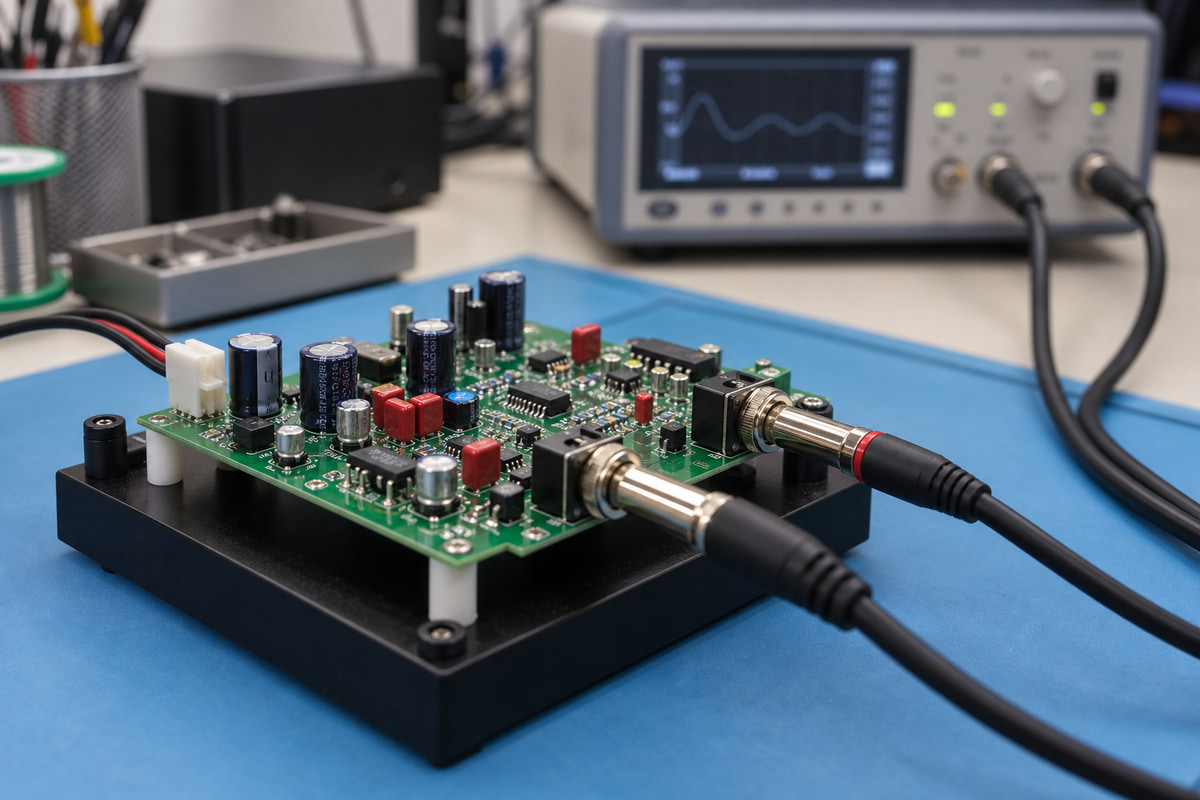
AOI can detect missing parts, polarity errors and visible solder defects, but it cannot confirm whether an assembled board meets its audio-performance targets. Finding hum, distortion or channel imbalance requires functional testing with known inputs, representative loads and measurable limits.
A production test normally progresses through four layers:
- bare-board electrical testing for opens and shorts;
- AOI for placement, polarity and visible solder defects;
- programming, power-rail and current checks;
- audio functional testing of the completed signal path.
The final test layer should reflect the product rather than apply the same measurement package to every audio board.
Power and output checks may include supply current, critical rail voltages and output DC offset. These results can expose incorrect parts, damaged devices, unstable rails or unsafe amplifier outputs.
Audio-performance checks may include gain, channel balance, frequency response, noise, hum and THD or THD+N. These measurements reveal differences that may be inaudible during a brief production check but become noticeable across channels or production batches.
Product-function checks may cover audio I/O, switches, potentiometers, indicators and communication interfaces. A musical instrument or mixer often needs these controls tested together with the audio path.
The required limits depend on the application. A voice or alarm board may need basic signal and function verification. A studio interface may require tighter noise and channel-matching limits. A power amplifier may also need testing under a representative load.
Production fixtures provide repeatable connections, input levels and loads while software records the result. When a board fails, the measurements also shorten diagnosis: hum can direct attention to grounding or supply ripple, while channel imbalance can indicate an incorrect passive value, solder defect or component-tolerance problem.
What Drives Cost and Lead Time as Production Volumes Grow?
Audio PCB assembly cost is mainly influenced by materials, assembly complexity, setup and testing. Lead time is usually determined by the slowest component or preparation step.
Components affect both cost and schedule. Specialist audio ICs, amplifiers, converters and unusual connectors may determine when production can start. MOQ and reel quantities can also increase material cost even when the individual component is inexpensive.
Setup costs become less significant at higher volume. Stencil preparation, programming setup, fixture preparation and production-line setup are distributed across more units as order quantity increases.
Assembly complexity affects throughput. Fine-pitch ICs, BGAs, through-hole connectors, large capacitors, heat sinks, switches and potentiometers may require additional assembly or inspection steps.
Testing affects production capacity. A basic power check is quick. A programmed multi-channel test measuring gain, noise or distortion takes longer, but it catches defects that AOI cannot see.
Long-lead ICs, customer-supplied material, PCB fabrication, fixture preparation, firmware availability, substitution approval and first-article approval can all influence the schedule. As volumes increase, material reservation becomes especially important. A large repeat order may assemble quickly once production starts, but one unavailable design-locked IC can still delay the entire batch.
For preliminary pricing, the BOM and basic board information can expose the main cost and sourcing constraints. Reviewing the released Gerbers, pick-and-place data, assembly drawings and test requirements together then helps separate true unit cost from setup, excess material and test preparation before production quantities are committed. A suitable PCB assembly manufacturer should make these assumptions visible in the quotation.
How EBest Circuit Supports Audio PCB Assembly from Validation to Volume Production
EBest Circuit supports audio PCB assembly from prototype validation through repeat production by controlling sourcing, assembly, testing and production changes within the same manufacturing workflow.
Engineering review: Before production, our team checks package-to-footprint consistency, polarity, thermal-pad solderability, specialist IC availability, approved substitutions and test access. This helps expose assembly or sourcing issues before they reach the production line.
Component sourcing: Standard parts can be factory-sourced while design-locked audio ICs remain customer-supplied or separately controlled. This prevents an unavailable codec, amplifier or specialist device from being replaced without approval.
Assembly and functional testing: We support SMT and through-hole assembly for boards combining fine-pitch ICs, connectors, large capacitors, switches and potentiometers. Testing can cover programming, rail voltage, current draw, gain, channel balance, noise, distortion and representative load behavior according to the product requirements.
Repeat production control: Approved BOM revisions, substitutions and test limits remain the production reference for later orders. Material traceability and controlled changes help keep each batch consistent with the validated build.
EBest Circuit has more than 20 years of PCB and PCBA manufacturing experience and operates under ISO 9001, ISO 13485, IATF 16949 and AS9100D quality systems. Monthly PCB capacity of approximately 260,000 square feet supports the transition from engineering validation to recurring production, while a reported 97% on-time delivery rate reflects the scheduling discipline needed across repeat orders.
These resources matter when they preserve the approved product as quantities rise. Customers gain clearer component control, fewer sourcing surprises and a manufacturing route that does not need to be rebuilt for every production batch.
FAQs About Audio PCB Assembly
Can EBest Circuit source most components while we supply one specialist audio IC?
Yes. Factory-sourced and customer-supplied components can be used in the same build. The specialist IC should be identified in the BOM and provided in suitable packaging, with sufficient quantity for normal production attrition.
What files are needed for audio PCB assembly?
Production normally requires Gerber and drill files, a controlled BOM, pick-and-place data and assembly drawings. Firmware, programming instructions and functional-test requirements should also be supplied when relevant.
Does every audio PCBA require a listening test?
No. Electrical measurements are normally more repeatable for production. Listening can complement them, but defined limits for gain, noise, frequency response, distortion or channel operation provide clearer pass/fail criteria.
How should audio component substitutions be approved?
The BOM should distinguish design-locked parts from components that permit alternatives. New substitutes should be reviewed against electrical, package and audio-related requirements before production use. Performance-sensitive changes may require a validation build.
Can the same manufacturer support prototypes and volume production?
Yes. Using the same controlled production route allows the approved BOM, sourcing rules, manufacturing process and test limits to carry forward from validation into repeat orders. The prototype removes production uncertainty; it does not define the commercial scale of the later program.
If you are preparing an audio PCB assembly for commercial production, send your BOM, expected quantities and available design files to sales@bestpcbs.com. EBest Circuit can review component availability, assembly risks and functional-test requirements before quotation and production planning.