Analog input vs digital input comes down to what the controller must learn from a field device. An analog input measures a continuously changing value, such as pressure or temperature. A digital input detects a defined ON/OFF state. Select the channel from the sensor output, required information, timing, noise, diagnostics, and PCB interface.
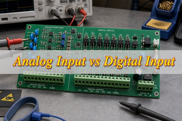
Analog Input vs Digital Input: What Is the Main Difference?
An analog input preserves magnitude; a digital input decides between defined states. A 4–20 mA pressure transmitter can report where pressure lies within a calibrated span. A 24 V proximity switch reports whether a target is present, not its distance.
The comparison includes the sensor, cable, connector, protection, filter, isolation, converter or threshold circuit, power, grounding, firmware, and test limits. A pin labeled “analog” or “digital” may still be unsafe for a field signal.
| Comparison Dimension | Analog Input | Digital Input | Engineering Impact |
| Information | Magnitude across a range | One of two defined states | Measurement versus state detection |
| Common field signals | 4–20 mA, 0–10 V, bridge, thermocouple | 24 V discrete, dry contact, PNP/NPN, logic level | Determines range, loading, and wiring |
| Receiving hardware | Signal conditioning and ADC | Threshold detector, buffer, comparator, or optocoupler | Changes BOM, area, calibration, and test coverage |
| Key performance limits | Accuracy, resolution, bandwidth, sample rate, drift | Thresholds, hysteresis, delay, debounce, switching rate | Requires different specifications and tests |
| Typical failure | Noisy, shifted, saturated, or drifting reading | False transition, missed state, or indeterminate level | Requires different diagnostic paths |
| Best fit | Variable process measurement | Events, interlocks, presence, and status | Matches the channel to the required information |
How Does an Analog Input Measure a Continuous Signal?
An analog input measures a continuous signal through six conversion stages. Each stage must preserve the required range, bandwidth, and accuracy.
- Identify the signal. Define the source type, range, impedance, common-mode voltage, return path, cable resistance, and fault voltage. Voltage, current, RTD, thermocouple, and bridge sensors require different front ends.
- Protect the connection. Limit ESD, surge, reverse polarity, overvoltage, and fault current. Check protection leakage and capacitance because they can shift high-impedance signals or reduce bandwidth.
- Convert and scale. Use a divider or amplifier for voltage, a burden resistor for current, controlled excitation for an RTD, cold-junction compensation for a thermocouple, or an instrumentation amplifier for a bridge. Verify component tolerance, common-mode range, output swing, and power dissipation.
- Filter and settle. Set the anti-alias filter from the required bandwidth and response time. For multiplexed ADCs, verify settling after each channel change, especially with high source impedance.
- Convert the signal. The ADC produces a code relative to its reference. A 12-bit ADC has 4,096 nominal codes, but offset, gain, nonlinearity, reference drift, noise, grounding, and layout reduce effective accuracy.
- Scale and verify. Convert the code into engineering units, build a channel error budget, and test minimum, midpoint, maximum, overrange, settling, and temperature behavior. Averaging reduces random noise but cannot correct clipping or systematic error.
How Does a Digital Input Detect ON/OFF States?
A digital input detects ON/OFF states through six decision stages. The channel must deliver a valid, protected signal to the controller without losing legitimate transitions.
- Define the source. Identify PNP, NPN, dry contact, open collector, push-pull, or logic-level output. Document polarity, normally open/closed behavior, logic meaning, and fail-safe state.
- Match voltage and current. Compare guaranteed source levels with guaranteed receiver ON/OFF ranges. Include loading and leakage; open-circuit voltage alone does not prove compatibility.
- Protect and translate. Add current limiting, polarity protection, transient clamping, level translation, buffering, or isolation. A 3.3 V GPIO is not a protected 24 V industrial input.
- Apply thresholds. Use a comparator or Schmitt trigger with adequate hysteresis. Verify threshold margin across supply, temperature, leakage, and ground shift.
- Filter invalid transitions. Set hardware filtering or debounce from the shortest valid event. Excess filtering can suppress encoder, flowmeter, or counter pulses.
- Capture and verify. Include isolation, comparator, sampling, PLC scan, capture hardware, and software delays. Test minimum HIGH/LOW time and ON, OFF, transition, power-off, and fault states at the controller logic point.
Which Analog Input vs Digital Input Examples Best Explain the Difference?
The clearest examples compare a measured value with a state from the same physical process. A tank may use an analog level transmitter for 0–100% measurement and a digital float switch for a high-level alarm. A motor may use analog current feedback for load trending and a digital overload contact for trip status. A cylinder may use an analog position sensor for travel and digital limit switches for endpoint confirmation.
| Application | Analog Input Example | Digital Input Example | Decision Value |
| Temperature | RTD or transmitter value | Overtemperature contact | Control value versus alarm state |
| Machine position | Linear position sensor | Limit switch | Travel feedback versus endpoint |
| Fluid system | Pressure or flow transmitter | Pressure or flow switch | Trend versus interlock |
| Motor monitoring | Current or vibration level | Run, fault, or overload contact | Condition versus operating state |
| Operator control | Speed potentiometer | Start/stop pushbutton | Setpoint versus command |
Choose by electrical interface and required information. Analog measurement supports control and trending; a switch provides a direct alarm or interlock. Encoders and PWM use digital pulses to encode variable information, while IO-Link, CAN, and RS-485 are digital communication interfaces rather than discrete inputs.
What Hardware Blocks Separate Analog Inputs from Digital Inputs?
An analog path scales and converts magnitude, while a digital path protects and resolves state. The analog chain normally uses protection, a burden resistor or divider, amplification or buffering, an anti-alias filter, optional isolation, an ADC, and a stable reference. Component tolerance, leakage, source impedance, and settling affect the measured value.
A digital path normally uses current limiting, transient and polarity protection, optional isolation, a comparator or Schmitt trigger, and a logic buffer or controller input. Threshold margin, hysteresis, leakage, input current, delay, and minimum pulse width determine whether the state is dependable.
- Analog interface definition: signal range, common-mode range, source impedance, return path, shield connection, cable resistance, and differential or single-ended behavior.
- Digital interface definition: ON/OFF voltage and current, PNP/NPN or dry-contact behavior, wetting current, pulse width, debounce, and fail-safe state.
- Shared checks: connector pinout, fault voltage, surge environment, isolation boundary, field ground, and power dissipation.
Isolation can appear in either chain, but its implementation differs. An isolated analog channel may use an isolation amplifier, isolated ADC, or converter plus digital isolator and isolated power. An isolated digital channel may use an optocoupler, digital isolator, isolated comparator, or relay interface. The isolation component alone is insufficient: the PCB must maintain the required separation, and any shield, test point, copper pour, mounting hardware, or power converter crossing the boundary must be reviewed.
How Do 4–20mA and 0–10V Analog Inputs Compare with 24V Digital Inputs?
4–20 mA and 0–10 V carry proportional measurements; a 24 V digital input carries a state. A current loop tolerates cable resistance provided that the loop has sufficient compliance voltage. A voltage input depends more directly on reference differences, loading, leakage, and voltage drop. A discrete input depends on valid ON/OFF current and voltage margins.
| Comparison Dimension | 4–20 mA Analog | 0–10 V Analog | 24 V Digital | Selection Check |
| Information | Proportional measurement | Proportional measurement | ON/OFF state | Magnitude or state? |
| Receiver | Burden resistor and ADC path | Divider/buffer and ADC path | Limiter and threshold/isolation path | Range, impedance, and dissipation |
| Wiring sensitivity | Loop compliance limits series drop | Reference and loading affect voltage | Threshold margin dominates | Cable, returns, and grounding |
| Diagnostics | Live zero may identify some faults | 0 V may be valid or faulty | OFF may be valid or faulty | Define detectable failures |
| Typical use | Industrial transmitters | Local controls and instrumentation | Switches and interlocks | Match the field-device data sheet |
For 4–20 mA, verify the loop voltage budget before choosing the burden resistor. The supply must cover the transmitter’s minimum operating voltage, cable and barrier drop, receiver drop, and other series elements at the highest expected current. A 250 Ω burden produces 1–5 V at 4–20 mA and dissipates 0.1 W at 20 mA, but component rating must also consider overrange and fault conditions. The value is an example, not a universal requirement.
For 0–10 V, verify the reference-to-ground difference, input impedance, common-mode range, rail linearity, shielding, and possible negative voltage. For 24 V digital inputs, verify guaranteed ON/OFF regions, source type, leakage, input current, hysteresis, and voltage drop across the protection circuit. A general-purpose PLC input is not automatically safety-rated.
How Do Analog Input Resolution and Sampling Rate Compare with Digital Input Switching Speed?
For analog input vs digital input performance, resolution and sampling rate describe analog measurement, while switching speed describes digital state detection. They are not interchangeable specifications and must be verified with different stimuli.
| Comparison Dimension | Analog Resolution | Analog Sampling Rate | Digital Switching Speed | Design and Verification |
| Primary purpose | Defines the smallest nominal code step | Defines how often conversions occur | Defines how fast transitions can be recognized | Start from required measurement change or event timing |
| Key calculation | Ideal code size = VFS/2N | Per-channel rate depends on ADC rate, channel count, and settling | Maximum rate depends on minimum HIGH/LOW time and total delay | Calculate the complete channel, not one component rating |
| Practical example | 0–10 V at 12 bits gives about 2.44 mV per nominal code | A multiplexed ADC may provide less usable rate per channel | A filtered 24 V input may reject a valid short pulse | Use actual range, filtering, topology, and controller timing |
| What it does not prove | Resolution does not prove accuracy or noise-free bits | Sample rate does not equal usable signal bandwidth | Fast device delay does not prove system event capture | Check sensor, front end, reference, filter, scan, and software |
| Main error or loss | Noise, offset, gain, reference error, drift, or clipping | Aliasing, incomplete settling, or channel-to-channel memory | Missed pulses, chatter, excessive latency, or indeterminate states | Test minimum, maximum, boundary, and dynamic conditions |
| Filter trade-off | Lower noise can improve stable readings | Narrower bandwidth increases response and settling time | Longer debounce rejects noise but reduces event rate | Preserve the fastest valid signal or pulse |
| Selection rule | Choose bits from meaningful change and the total error budget | Choose rate from bandwidth, channels, acquisition, and latency | Choose speed from pulse width, delay, filtering, capture, and scan time | The slowest stage sets usable system performance |
| Verification method | Inject calibrated increments and measure noise-free response | Apply timed steps and verify settling on every channel | Apply worst-case pulse trains at minimum valid amplitude | Test at supply and temperature limits with real firmware timing |
Why Do Analog Input vs Digital Input Circuits Respond Differently to Noise and Interference?
In analog input vs digital input circuits, noise changes the analog reading directly but affects the digital result mainly when it crosses a threshold or corrupts timing. Digital inputs still fail when interference crosses a threshold, ground shift moves the signal outside its valid range, or filtering removes a legitimate short pulse.
Analog interference appears as variation, offset, ripple, or saturation; narrow bandwidth reduces noise but increases settling time. Digital inputs tolerate disturbances inside their noise margin, but slow edges, insufficient hysteresis, ground shift, or threshold-crossing transients can cause chatter or false states.
- Connector disturbance: Quantify the normal signal and credible interference at the connector.
- Digital margin: Verify threshold margin across supply, temperature, leakage, and ground shift.
- Analog bandwidth: Set bandwidth from the required response, then measure settling.
- PCB separation: Keep relays, converters, clocks, gate-drive loops, and high-current traces away from sensitive analog paths.
- Immunity validation: Test immunity to ESD, burst, surge, cable transients, and common-mode disturbances against the end-product requirements.
What Signal Conditioning and Protection Does Each Input Type Require?
Analog conditioning must preserve magnitude, while digital conditioning must preserve state and timing. Select the divider or burden resistor for range and dissipation, keep amplifier common-mode and output swing within limits, set filter cutoff from signal bandwidth and ADC settling, and include reference and tolerance errors in the budget. Protection leakage and capacitance must not corrupt the source.
Protection must survive the fault without invalidating normal measurements or states. A TVS diode must be coordinated with series impedance and downstream absolute maximum ratings; its dynamic clamp voltage, leakage, and capacitance matter. A resistor must be checked for working voltage, pulse energy, temperature rise, and fault dissipation, not only nominal resistance. Where sustained overvoltage is credible, a fuse, resettable protector, current limiter, or disconnect device may be necessary.
- Define normal and fault ranges. Include source impedance, cable, grounding, and power-off states.
- Select protection. Coordinate current limiting, clamps, TVS devices, fuses, and isolation with the available fault energy.
- Set the analog transfer path. Calculate scaling, gain, bandwidth, settling, and error contribution.
- Set the digital decision path. Calculate ON/OFF current, thresholds, hysteresis, delay, and minimum pulse width.
- Verify at temperature and supply limits. Nominal bench behavior does not prove boundary margin.
How Are Analog and Digital Inputs Used in PLC Systems?
A PLC digital module reports states, while an analog module reports scaled measurements. The digital input evaluates field voltage or current against ON/OFF thresholds and places the state in process data. Input filtering can suppress bounce and short noise pulses, but it adds delay. High-speed counters require channels specified for the pulse frequency and minimum HIGH/LOW time.
Match the module to two-, three-, or four-wire transmitters; PNP or NPN sensors; shared or isolated returns; and required wire-break or overrange diagnostics. Check isolation, input impedance, update time, accuracy over temperature, terminal wiring, and fuse requirements in the module data sheet.
PLC configuration must match the physical module and field wiring. For an analog channel, select current or voltage mode, engineering-unit scaling, filtering, update behavior, and diagnostic limits. If a 4–20 mA transmitter is scaled as 0–20 mA, the value and fault interpretation will be wrong even when the wiring is correct. For a digital channel, confirm input polarity, filtering time, normally open or normally closed logic, and whether the application needs a standard, interrupt, counter, or safety input.
At commissioning, compare the terminal signal, raw module value, and scaled PLC tag. This separates field, module, and program faults. Review individual, group, or backplane isolation before combining commons; software forcing does not verify field wiring or protection.
How Should You Choose Between Analog and Digital Sensor Inputs for Automation?
Choose the required information first: measurement, state, event, or a combination. Then match the receiving channel to the sensor’s electrical output and to normal, boundary, and fault conditions. This keeps the choice between analog and digital sensor inputs tied to the control task rather than the connector label.
- Define the control task. Specify the range, alarm, event, or interlock.
- Read the sensor output specification. Identify 4–20 mA, 0–10 V, bridge, thermocouple, dry contact, PNP, NPN, open collector, or logic level.
- Match electrical limits. Check voltage, current, impedance, common-mode range, leakage, thresholds, and fault exposure.
- Set performance. Define analog accuracy, bandwidth, sample rate, and drift or digital delay, pulse width, debounce, and switching rate.
- Assess installation conditions. Include cable length, shielding, grounding, nearby switching, temperature, moisture, and isolation.
- Define diagnostics. Decide how the system distinguishes a valid minimum or OFF state from open wire, short circuit, or lost sensor power.
- Verify the complete channel. Test the sensor, cable, PCB, scaling or logic, and fault response together.
Prefer analog when control quality depends on how much; prefer digital when the decision depends only on whether. A proportional valve controller needs position or pressure magnitude, while an emergency stop, guard switch, or end limit needs an unambiguous state. If the process needs an alarm threshold that may change in software, an analog measurement provides flexibility. If the threshold must remain independent of the controller, a separate switch can provide a distinct hardware signal.
For procurement, specify the signal standard, range, sourcing or sinking behavior, supply, pinout, isolation, cable, environment, accuracy or timing, and fault diagnostics. Analog channels may add calibration and shielding costs; several digital switches may be needed to represent multiple operating points.
How Should Mixed Analog and Digital Input Data Acquisition Hardware Be Designed on a PCB?
Design mixed-input PCBs from voltage domains, current paths, timing, and fault containment. The hardware must protect field connections without allowing switching current, ground shift, or shared conversion resources to corrupt analog results or digital events.
- List channel roles and domains. Identify measurements, states, triggers, interlocks, field power, chassis, isolated supplies, analog ground, and digital ground.
- Place protection at each connector. Keep ESD, surge, polarity, and current-limiting components near the entry point.
- Keep input chains compact. Group analog scaling, amplification, filtering, reference, and ADC components; group digital protection, isolation, threshold, and buffer components.
- Control return currents. Maintain a continuous reference where appropriate and prevent fast digital returns from crossing sensitive analog paths.
- Allocate conversion and timing resources. Account for ADC multiplexing, per-channel settling, digital timestamp needs, shared clocks, processor load, and simultaneous operation.
- Separate noisy nodes. Increase distance from relays, switching regulators, gate-drive loops, clocks, memory buses, and high-current traces.
- Implement real isolation boundaries. Check creepage, clearance, slots, copper keepouts, component ratings, and isolated power against working voltage and applicable safety conditions.
- Provide diagnostics and test access. Include safe test points, range status, wire-break or overrange handling, calibration storage, and production-test access.
- Review before release. Verify connector pinout, fault paths, shields, return paths, isolation-domain labels, and simultaneous analog/digital operation.
Partition placement by current flow and fault energy, not by labels alone. Put connector protection first, then scaling or current limiting, isolation where required, and finally sensitive conversion or logic. Keep a short, low-inductance return for transient clamps to the intended chassis or reference node. Do not route surge current through the analog ground used by the ADC reference.
Review analog and digital tolerances as channel-level stacks, including scaling, offset, reference, thresholds, leakage, delay, and fault dissipation. Keep test points on the correct side of each isolation barrier and define how production fixtures stimulate, identify, calibrate, and record every channel.
How Can Analog Input vs Digital Input Circuits Be Tested, Calibrated and Troubleshot?
Analog input vs digital input testing must cover boundaries and faults, not only nominal operation. Use calibrated sources and define acceptance limits before testing.
- Inspect the unpowered assembly. Verify polarity, values, spacing, connector mapping, solder quality, shorts, and resistance to ground.
- Power each domain with current limiting. Check rails, references, isolated supplies, and unexpected heating.
- Test digital thresholds and timing. Sweep rising and falling levels; verify hysteresis, OFF leakage, ON current, minimum pulse width, debounce, and fail-safe state.
- Test analog endpoints and midpoints. Inject calibrated minimum, midpoint, and maximum values; check offset, gain, linearity, saturation, and channel consistency.
- Calibrate where required. Calculate coefficients from traceable stimuli, store them with channel identity and revision, and verify the corrected result independently.
- Measure dynamic response. Apply analog steps and digital pulses; record settling, latency, missed events, and filter effects.
- Inject credible faults. Test open wire, safe shorts, reversal, overrange, and loss of field power.
- Evaluate interference. Operate nearby relays, motors, converters, and communications while monitoring readings and transitions.
- Correlate hardware and software. Compare connector signal, conditioned node, ADC code or logic state, scaling, alarms, and displayed value.
- Define production limits. Convert results into fixture stimuli, pass/fail windows, calibration records, and traceable functional tests.

Trace the signal stage by stage instead of replacing components by guesswork. Disconnect or simulate the field source, inject a known value at the connector, and follow it through each accessible node. If the conditioned voltage is correct but the reported value is wrong, investigate the ADC reference, channel selection, calibration, and scaling. If the connector signal is correct but the conditioned node is wrong, check for damaged protection components, incorrect component values, leakage, loading, common-mode violations, or solder defects.
Capture intermittent digital faults at the field and receiver nodes to check bounce, ringing, thresholds, delay, and pulse width. For analog drift, log sensor output, reference, supply, temperature, and converted data. Set production limits from design tolerance and measurement uncertainty, then record revision, stimulus, calibration, result, and status.
What Are the Most Common Questions About Analog Input vs Digital Input?
Q1: Can one universal input channel accept both analog and digital sensors?
A1: Yes, but only when hardware provides selectable protection, range, analog-conversion, and digital-threshold paths. Firmware selection cannot make one fixed front end safe for every source. Treat it as multiple validated electrical modes.
Q2: What happens if 24 V is connected directly to an MCU input?
A2: A typical low-voltage MCU pin can be overstressed or destroyed. Use current limiting, clamping, level translation, or isolation designed for the fault voltage, duration, and source impedance.
Q3: Is a pulse or frequency signal a digital input?
A3: Usually, because the receiver counts threshold crossings. Check frequency, minimum HIGH/LOW time, delay, and counter capability before using a high-speed digital or counter channel.
Q4: How should unused inputs be terminated?
A4: Do not leave a high-impedance input floating. Apply the receiver’s recommended bias or termination and configure a defined, safe, and detectable state.
Q5: Can analog and digital inputs share one connector?
A5: Yes, after reviewing pin assignment, spacing, returns, shielding, and miswiring. Use a keyed, documented pinout and protect an analog pin from credible digital-supply faults.
Q6: Is an I2C, SPI, CAN, or RS-485 sensor a digital input?
A6: It provides digital data but is not a discrete ON/OFF input. It needs protocol handling and the correct logic interface or transceiver. Classify it as a digital communication interface.
Q7: What should an input do when the controller is powered off?
A7: The field source must not back-power an unpowered controller through protection diodes or interface components. Check current paths for every power sequence and use suitable blocking, limiting, buffering, or isolation so the channel enters a defined power-off state.
Q8: Can one sensor provide both an analog value and a digital alarm?
A8: Yes. Some sensors provide a proportional output plus a configurable switch output. Treat them as two electrical interfaces: verify each output type, reference, loading, timing, and fault behavior before connecting them to separate compatible input channels.
Q9: When is a ratiometric analog measurement useful?
A9: Ratiometric conversion is useful when the sensor output and ADC reference change with the same excitation voltage. The shared variation can cancel in the calculated ratio, provided the excitation and reference remain properly related and within their operating ranges.
Q10: How can input impedance be checked without disturbing the circuit?
A10: Measure the voltage change produced by a known source resistance or apply a small, controlled test signal within safe limits. Include instrument loading and protection leakage in the calculation; use a buffered method when the source is too sensitive for direct probing.
Send your schematic, Gerber files, BOM, input ranges, channel count, isolation requirements, operating environment, and test criteria to EBest Circuit at sales@bestpcbs.com for a PCB and PCBA quotation.