PCB manufacturing PCB manufacturing
Home > Blog

Indoor LED Display Aluminum PCB – Thermal Solution for Meeting Room Manufacturers

March 23rd, 2026

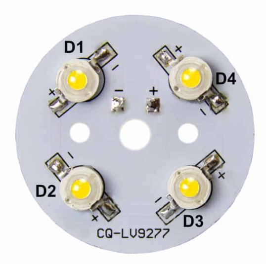
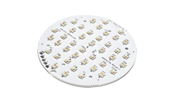
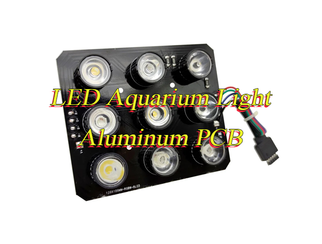
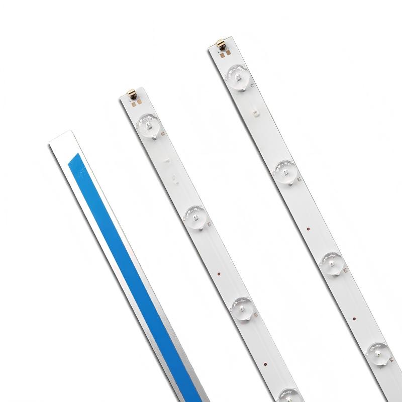
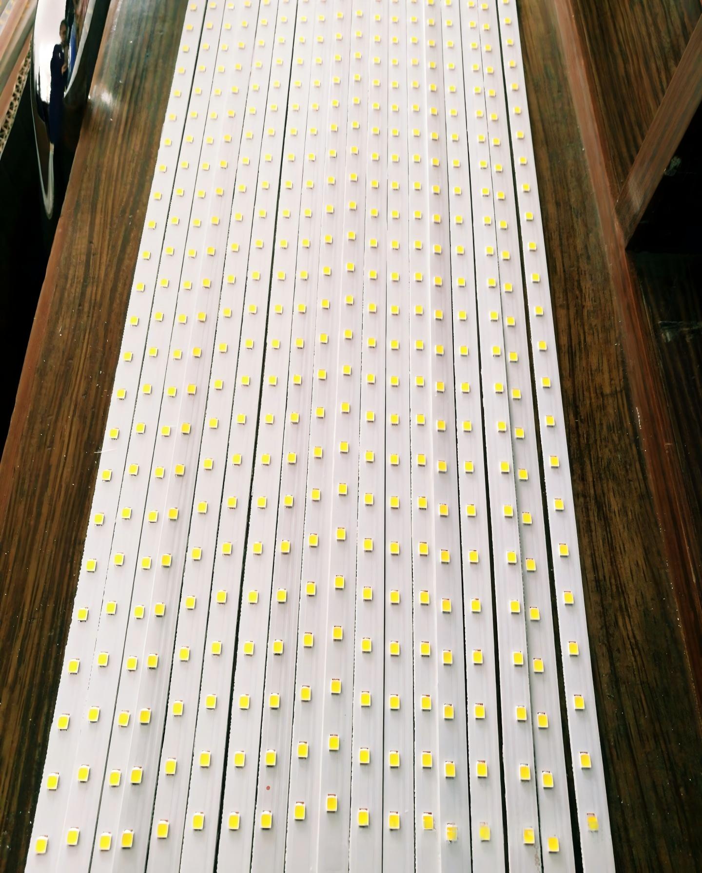
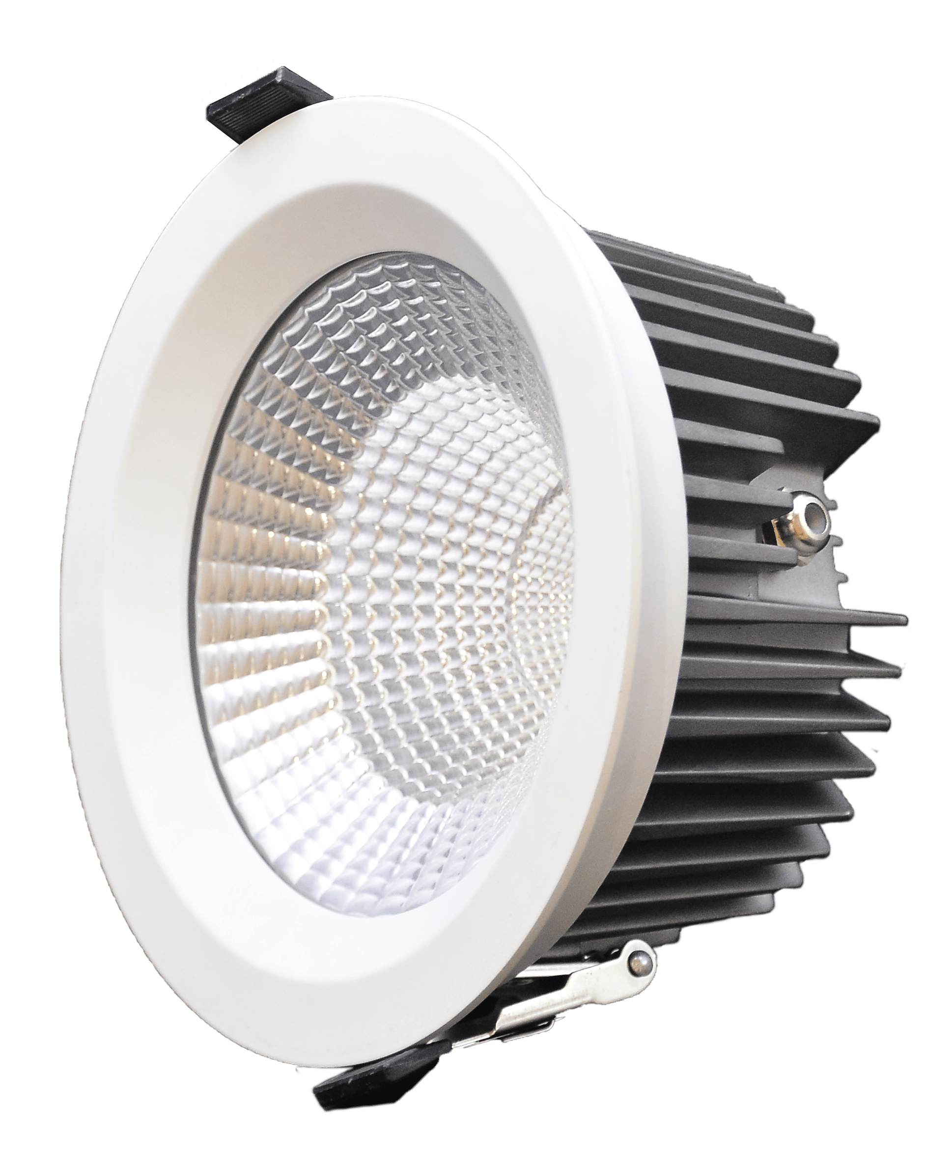
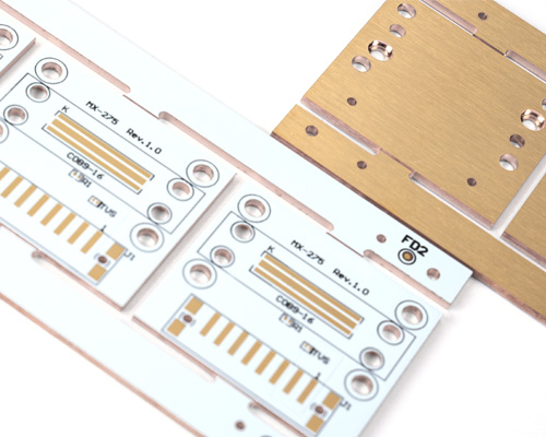
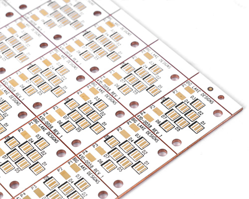
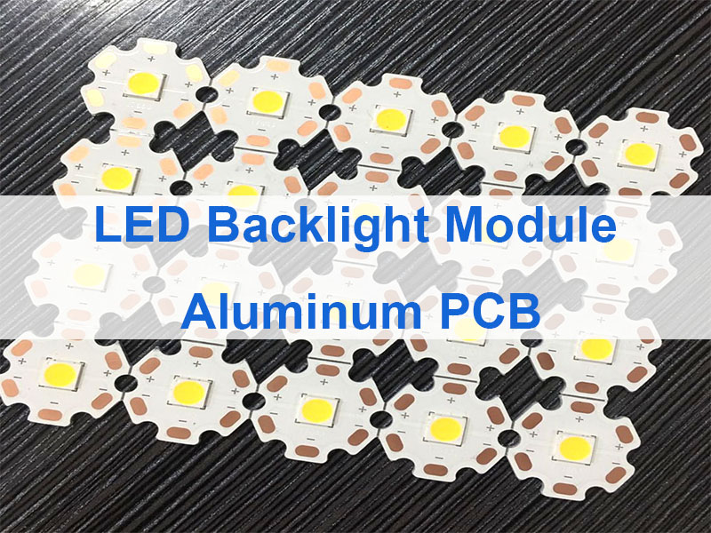
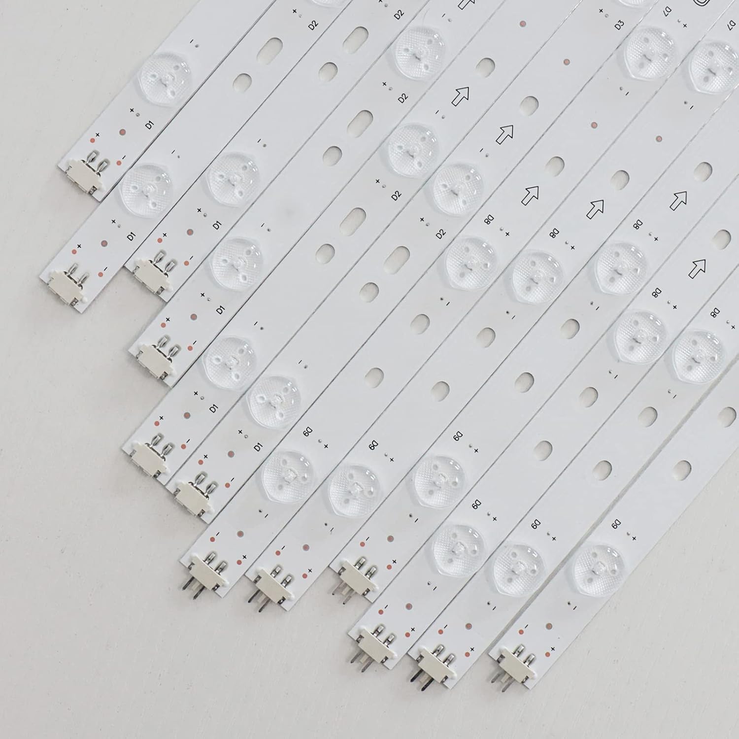
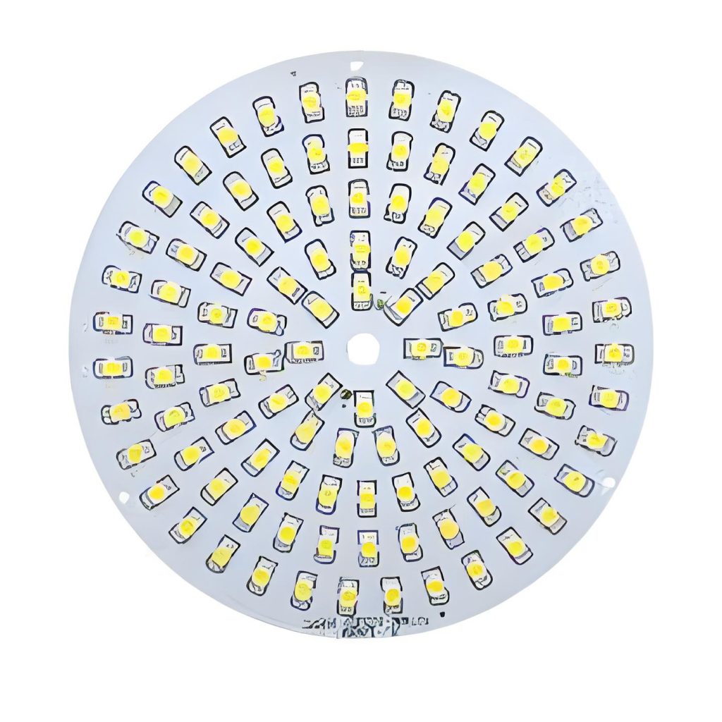
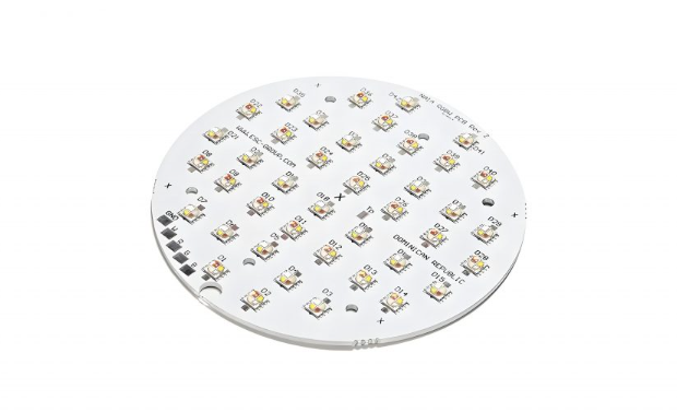
Indoor LED Display Aluminum PCB is a metal-core printed circuit board designed for indoor LED display modules, using an aluminum base to improve heat dissipation, enhance structural stability, and support reliable long-term display performance.

At EBest Circuit (Best Technology), we provide Indoor LED Display Aluminum PCB manufacturing with engineering support, fast response, and production control for stable indoor LED applications. We support customers who need dependable heat spreading, solid soldering performance, and repeatable quality for batch orders.

Core parameters customers often ask for

  • Base material aluminum core / metal core structure
  • Copper thickness 1oz, 2oz, or project-based design
  • Board thickness custom according to module structure
  • Thermal dielectric selected for indoor LED heat transfer needs
  • Surface finish HASL, ENIG, OSP, or project requirement
  • Application indoor fine-pitch LED modules, meeting room displays, commercial indoor screens

Why choose us for this product

  • Quality controlled fabrication and assembly process for stable display modules
  • Lead time responsive support from sampling to volume builds
  • Service engineering communication that focuses on manufacturability and project fit
  • Supply continuity one-stop coordination for PCB fabrication and related assembly support

Therefore, a well-built aluminum PCB is not just a substrate choice, but the thermal foundation of indoor LED display reliability. In practice, buyers who start from board structure usually reduce downstream instability in the full module build.

Indoor LED Display Aluminum PCB

What Is an Indoor LED Display Aluminum PCB and How Does It Work?

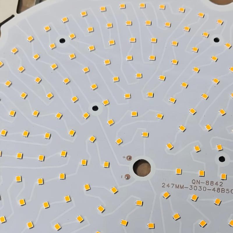
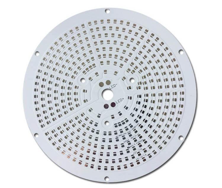
An Indoor LED Display Aluminum PCB is a metal-core circuit board designed to carry LED packages and related circuitry while moving heat away from the light source more efficiently than a standard FR4 board. It typically includes a copper circuit layer, a thermally conductive dielectric layer, and an aluminum base that spreads heat across a wider area.

For indoor LED displays, this structure matters because dense LED layouts can create local heat concentration. When heat is guided away quickly, the display is more likely to keep stable brightness, cleaner color performance, and longer service life.

Basic structure

LayerFunctionWhy It Matters for Indoor LED Displays
Copper Circuit LayerCarries current and signal pathsSupports LED connection stability and layout accuracy
Thermal Dielectric LayerTransfers heat while keeping electrical insulationHelps control heat flow from LEDs to the base
Aluminum BaseSpreads and releases heatImproves thermal balance and mechanical support

Overall, this board type is chosen when thermal control and dimensional stability matter as much as electrical connectivity. This means it is especially suitable for indoor LED modules expected to run for long periods in conference and presentation environments.

Indoor LED Display Aluminum PCB

Why Is Aluminum Better Than Standard FR4 for Indoor LED Display Thermal Control?

For many indoor LED display projects, aluminum offers a more practical thermal path than standard FR4 because it spreads heat faster and supports better mechanical rigidity. This is especially valuable in fine-pitch or high-density indoor displays where localized heating can affect both image quality and solder joint life.

FR4 still works in many electronics, but indoor LED display modules often benefit from the metal-core approach when brightness stability and long operating time are priorities. Aluminum also helps support flatter panel construction, which is useful when multiple modules must align into one seamless display surface.

Aluminum PCB vs FR4 for indoor LED display use

ItemAluminum PCB for Indoor LED DisplayStandard FR4 PCB
Heat spreadingStrongModerate
Suitability for dense LED arraysHighLower in thermal-heavy designs
Board rigidityBetter mechanical supportGeneral-purpose support
Risk of thermal accumulationReduced with correct stack-upHigher in high-density LED zones
Fit for quiet indoor display designVery suitableMore limited in passive thermal design

As a result, aluminum is often the safer choice when the display must stay visually stable without relying heavily on extra cooling methods. From an engineering perspective, that makes the board itself part of the thermal solution rather than just a wiring platform.

Indoor LED Display Aluminum PCB

How Does an Aluminum PCB Improve Meeting Room LED Display Performance?

In meeting rooms, the display is viewed at close distance, often for long sessions, so thermal consistency directly affects visual experience. A better thermal base helps the screen keep uniform brightness, cleaner white balance, and lower risk of color variation across modules.

It also supports quieter system design. Many indoor meeting room displays prefer passive or low-noise thermal strategies, and a well-designed Aluminum PCB for Indoor LED Display helps make that possible.

Performance gains that matter in meeting rooms

  • More stable brightness during long presentations
  • Lower thermal stress on LED packages and solder joints
  • Better module flatness for close-view visual consistency
  • Reduced chance of hotspots in dense pixel layouts
  • Improved fit for quiet indoor environments

In real-world applications, meeting room screens are judged by visual comfort as much as technical output. Notably, thermal control at the PCB level helps support both at the same time.

What Pain Points Do Buyers Face with Indoor Aluminum PCB LED Display Projects?

Buyers usually do not struggle with naming the product. They struggle with whether the board will stay stable after assembly, run cool enough in dense layouts, and remain consistent across batches. The most repeated concerns are warpage, poor heat flow, solder fatigue, uneven brightness, and production inconsistency from one build lot to another.

These issues often appear when the substrate choice, dielectric performance, copper design, and assembly process are not aligned from the start. That is why many indoor LED projects fail quietly during long operation, not during first power-on testing.

Common pain points and how we address them

Pain PointWhat It CausesHow EBest Circuit Helps
Heat buildup in dense LED areasBrightness drift and shorter lifeThermal-focused stack-up and process review
Board warpage or flatness variationPoor module alignment and visual inconsistencyControlled fabrication and dimensional inspection
Solder joint stressIntermittent failures over timeProcess control for stable assembly compatibility
Batch-to-batch inconsistencyMixed display performance across modulesStandardized production control and traceable workflow
Unclear technical supportDesign delays and manufacturability issuesEngineering communication before mass build

In short, the biggest risk is not one dramatic defect, but many small inconsistencies adding up in the finished display wall. To sum up, choosing a supplier that understands both PCB fabrication and LED display application logic helps prevent that chain reaction.

How Should PCB Aluminum for Indoor LED Display Be Designed for Better Heat Dissipation?

The answer is to treat thermal design as a full-board system, not a single material choice. A strong PCB Aluminum for Indoor LED Display design combines the right base thickness, proper dielectric selection, current path planning, copper balance, LED spacing, and interface design with the module frame or cabinet.

Many overheating problems come from poor heat path continuity. Even if the board uses aluminum, the result will be limited if copper distribution is uneven, thermal bottlenecks remain near LED clusters, or module contact to the supporting structure is weak.

Design focus areas

  • Keep heat-generating LEDs evenly distributed where possible
  • Use copper layout that supports both current carrying and heat spreading
  • Avoid sharp local thermal concentration under dense pixel zones
  • Match board flatness needs with module and frame requirements
  • Consider assembly process compatibility from the layout stage

Recommended design checkpoints

CheckpointWhy It Matters
Dielectric thermal performanceControls how effectively heat moves to the aluminum base
Copper balanceSupports thermal spreading and dimensional stability
LED package spacingReduces hotspot concentration
Panel flatnessHelps maintain seamless indoor display alignment
Assembly compatibilityImproves solder reliability and production repeatability

Meanwhile, the best thermal result usually comes from coordinated board and mechanical design rather than isolated PCB optimization. This means the aluminum substrate should be planned as part of the full display module architecture.

How Do We Manufacture LED Display Indoor Aluminum PCB for Stable Quality?

Stable manufacturing begins with material control and continues through imaging, etching, lamination, profile control, surface finishing, and final inspection. For LED Display Indoor Aluminum PCB products, process discipline is important because indoor LED modules require both thermal function and dimensional consistency.

Even small process variation can affect flatness, solderability, or thermal transfer behavior. That is why a production flow for LED display aluminum boards must focus on repeatability, not just output speed.

Typical manufacturing flow

  • Material confirmation based on thermal and structural requirement
  • Circuit pattern creation and copper processing
  • Dielectric and base structure control
  • Drilling, routing, and profile shaping
  • Surface finish selection for assembly compatibility
  • Electrical and dimensional inspection
  • Packing protection for safe shipment and module assembly readiness

What we pay special attention to

  • Dimensional stability across batches
  • Clean surface condition for reliable assembly
  • Flatness control for seamless module installation
  • Traceable production workflow for project consistency

From a manufacturing standpoint, indoor LED boards require consistency more than visual complexity. In practical terms, that consistency is what protects the final display from uneven module behavior after installation.

What Services and Certifications Should You Expect from an Indoor LED Aluminum PCB Supplier?

A capable supplier should provide more than bare board fabrication. You should expect technical communication, project review, documentation support, quality traceability, and clear manufacturing control for indoor LED applications. Certifications also matter because they indicate that the quality system is managed, repeatable, and suitable for customers who need dependable supply.

At EBest Circuit (Best Technology), we support LED-related PCB and PCBA projects with coordinated service from inquiry to delivery. For customers building Indoor Aluminum PCB LED Display products, this reduces handoff friction and helps keep engineering and production aligned.

Our service scope

Service ItemWhat It Supports
PCB fabricationAluminum and application-matched board manufacturing
Engineering reviewManufacturability and project feasibility check
Assembly supportBetter connection between bare board and final product build
Project communicationFaster clarification of drawings and production needs
Traceable workflowImproved batch control and follow-up support

Certificates

CertificateWhat It Signals
ISO 9001Managed quality system
ISO 13485Controlled quality practices for medical-related manufacturing environments
IATF 16949Automotive-oriented process discipline
AS9100DAerospace-oriented quality management capability
RoHS / REACH compliance supportMaterial and regulatory alignment for many global projects

Likewise, certifications alone do not guarantee a good project result, but they do show whether the supplier is operating with structured control. For buyers, that structure often translates into more predictable performance and smoother communication.

What Related Questions Do Buyers Commonly Ask Before Ordering Aluminum Indoor LED Display PCB?

Before placing an order, most buyers ask practical questions rather than abstract ones. They want to know which stack-up fits indoor fine-pitch modules, how flat the board can stay, whether the surface finish supports reliable assembly, and how to match the board to the module frame and display cabinet.

These questions are useful because they reveal the real success criteria of the project. A good supplier should answer them clearly before production starts.

High-interest questions often asked during inquiry

  • What board structure is best for indoor fine-pitch LED modules?
  • How do you control flatness for seamless indoor display assembly?
  • Which surface finish is better for LED module soldering?
  • How do you verify thermal performance in a dense LED layout?
  • Can the board design support long daily operating hours?
  • How do you maintain consistency across repeat production lots?

Besides, clear answers at the inquiry stage usually reduce revision loops later in the project. In engineering terms, early question quality often predicts final manufacturing smoothness.

How Does Display Indoor LED Aluminum PCB Support Long-Term Reliability?

Long-term reliability comes from controlling temperature, stress, and process variation together. A Display Indoor LED Aluminum PCB improves the first part by giving heat a faster path away from LEDs, but the full reliability result also depends on flatness control, soldering compatibility, and consistent material behavior over time.

When these factors work together, the display is more likely to maintain image uniformity and resist gradual degradation during long operation cycles. That matters in meeting rooms where the display must look stable every day, not only during initial testing.

Reliability factors linked to board design

Reliability FactorBoard-Level Impact
Heat controlHelps reduce LED aging speed
Mechanical stabilitySupports better module alignment
Solder compatibilityImproves joint integrity over long use
Batch consistencyKeeps screen performance more uniform
Clean manufacturingReduces hidden process-related failure risk

By comparison, a board chosen only for basic connectivity may pass early testing but create hidden weakness later. Hence, reliability in indoor LED display projects should be designed into the substrate from the beginning.

What Are the Best Application Cases for Aluminum Indoor LED Display PCB?

The strongest application cases are indoor environments that demand close viewing, long operating time, and strong visual consistency. In these settings, Aluminum Indoor LED Display PCB products help support cleaner thermal performance and better screen stability than many standard board approaches.

Four industries stand out because they depend heavily on indoor display clarity and operating consistency. These examples also show why the board choice matters at the system level.

Typical industry cases

IndustryTypical UseWhy Aluminum PCB Helps
Corporate Meeting RoomsPresentation walls and boardroom screensSupports stable brightness and quiet thermal behavior
Control RoomsContinuous-operation monitoring displaysImproves long-run thermal stability and screen consistency
Retail and ShowroomsIndoor branding and product presentation wallsHelps maintain visual uniformity during long opening hours
Education and Training SpacesLecture screens and collaborative display systemsProvides reliable operation for repeated daily use

Example use case

A fine-pitch indoor conference display with long daily operating time usually needs more than visual resolution. It also needs a board that supports uniform heat spreading across many closely packed LEDs, especially when the system is expected to remain quiet and visually consistent during extended meetings.

Ultimately, the best application is any indoor LED display where stable image quality matters over time. For that reason, aluminum PCB structures are often selected in projects that value both visual precision and operational confidence.

How Should You Choose the Right Supplier for LED Indoor Display Aluminum PCB?

You should choose a supplier that understands how PCB fabrication affects final display behavior. That means the supplier should be able to discuss thermal structure, flatness, copper design, assembly compatibility, process consistency, and project documentation with confidence.

A strong supplier is not only a factory. It is also a technical partner that can identify hidden manufacturability risks before they turn into module instability or field complaints.

What to evaluate during supplier selection

  • Experience with LED-related thermal board applications
  • Ability to communicate technical details clearly
  • Consistency in fabrication control and inspection
  • Support for repeat production with stable quality
  • Service response during design and order preparation
  • Quality system and certification visibility

Why many customers choose us

EBest Circuit (Best Technology) combines PCB manufacturing capability with application-focused support for demanding projects. For buyers of LED Indoor Display Aluminum PCB, that means smoother technical discussion, controlled production, and a stronger path from drawing to delivery.

Correspondingly, the right supplier helps reduce technical uncertainty before the first production lot begins. Overall, that is one of the most valuable advantages in indoor LED display manufacturing. If you are looking for a dependable supplier for Indoor LED Display Aluminum PCB, EBest Circuit (Best Technology) is ready to support your project. We provide professional Indoor LED Display Aluminum PCB products for indoor display applications. For inquiries and orders, pls feel free to contact us at sales@bestpcbs.com.

FAQs About Indoor LED Display Aluminum PCB

How does Indoor Aluminum PCB LED Display improve thermal performance?

It improves performance by transferring heat from the copper layer through a thermally conductive dielectric into the aluminum base, where heat can spread more efficiently. This helps reduce hotspot buildup and supports more stable long-term display operation.

Why use LED Display Indoor Aluminum PCB in meeting room screens?

Meeting room displays are viewed at short distance and often run for long sessions, so thermal stability directly affects image uniformity and reliability. Aluminum PCB structures help support quiet operation, stable brightness, and better module flatness.

How do you choose PCB Aluminum for Indoor LED Display?

Start by checking thermal requirements, LED density, board thickness, copper design, assembly compatibility, and flatness needs. The right choice is the one that matches both the electrical design and the mechanical structure of the display module.

What is the difference between FR4 and Indoor LED Aluminum PCB Display?

FR4 is a general-purpose substrate, while aluminum PCB includes a metal base that spreads heat more effectively. For indoor LED display modules with dense LED layouts, aluminum usually offers stronger thermal support and better dimensional stability.

How can EBest Circuit support Display LED Indoor Aluminum PCB projects?

We support customers with PCB fabrication, engineering communication, controlled production workflow, and quality-focused service for indoor LED applications. This helps reduce manufacturing risk and improves consistency from sample stage to repeat orders.

Can Aluminum Indoor LED Display PCB support long operating hours?

Yes, when the stack-up, dielectric, copper layout, and assembly conditions are designed properly, aluminum PCB structures are well suited for indoor displays that need stable thermal behavior during extended daily use.
You may also like

LED Spotlight Aluminum PCB – High Thermal Conductivity for Focused Lighting

March 23rd, 2026

Are you struggling with heat buildup, blurred beam focus, or short lifespans in your LED spotlights that could be fixed with a high-performance LED spotlight aluminum PCB? This guide breaks down everything you need to know about LED Spotlight Aluminum PCB, covering common industry challenges, targeted solutions, thermal performance fundamentals, and practical selection and testing tips for focused, reliable LED spotlight operation.

LED Spotlight Aluminum PCB, https://www.bestpcbs.com/blog/2026/03/led-spotlight-aluminum-pcb/

Common Challenges of LED Spotlight Aluminum PCB

  • Does insufficient thermal conductivity cause persistent heat buildup in LED spotlight aluminum PCB?
  • Can poor substrate bonding lead to layer separation and spotlight performance decline?
  • Does imprecise circuit layout disrupt beam alignment and cause light offset?
  • Can low-quality base aluminum reduce overall LED spotlight service life?
  • Does inconsistent thermal distribution create uneven brightness across the spotlight beam?

Our Solutions to the Above Challenges of Aluminum PCB for LED Spotlight

  • We engineer every LED spotlight aluminum PCB with multi-grade high thermal conductivity layers and optimized thermal via arrays, which quickly transfer concentrated heat from LED chips to the aluminum base and external heat sinks. This eliminates hotspots that damage chips and degrade performance, keeping junction temperatures within safe operating ranges for consistent lighting output.
  • We use industrial-grade, high-adhesion ceramic-filled dielectric materials paired with precision lamination technology under controlled temperature and pressure. This creates a permanent, stable bond between the copper circuit layer and aluminum base, preventing delamination even under long-term high-temperature continuous operation, and boosting overall structural durability.
  • Our team uses ultra-precision laser etching and computer-aided circuit layout design, with strict component placement tolerances and centered LED chip mounting. This locks in fixed beam alignment, eliminates light offset and uneven focus, and ensures the spotlight delivers sharp, consistent brightness as designed for commercial and architectural use.
  • We source 100% pure, high-grade aluminum base materials with consistent thermal conductivity and mechanical rigidity, rejecting low-purity alloys that warp or conduct heat poorly. This upgrade strengthens substrate durability, speeds up overall heat dissipation, and directly extends the continuous operational lifespan of the entire LED spotlight assembly.
  • We optimize full-surface thermal pathway design and uniform copper distribution across the LED spotlight aluminum PCB, ensuring even heat spread across all LED components. Balanced thermal control stops brightness fluctuations and flickering, delivering steady, flicker-free light output that meets quality standards for retail, hospitality and industrial spotlight applications.

Why Choose EBest as Your LED Spotlight Aluminum PCB Manufacturer?

EBest is a specialized, customer-focused LED spotlight aluminum PCB manufacturer with 20+ years of deep industry expertise, dedicated to solving the most pressing thermal and design pain points that cost lighting brands time, revenue, and customer trust. We don’t just build PCBs, we engineer solutions that directly boost your LED spotlight product quality, extend service life, and cut field failure rates, aligning every production decision with your bottom line and market competitiveness.

Our fully dedicated aluminum PCB production lines are equipped with precision automated equipment and run on 6-step strict quality control protocols, covering material inspection, lamination, etching, and finished product testing. Industry testing data confirms our LED Spotlight Aluminum PCB reduces LED chip junction temperature by up to 28°C compared to standard aluminum PCBs, and boosts spotlight service life by over 60% while cutting in-field failure rates by more than 75%.

Our in-house team consists of senior PCB engineers and LED lighting design specialists with an average of 15+ years of industry experience, offering free personalized technical support, custom circuit layout optimization, and free prototype testing for every client. We act as your long-term technical partner, not just a supplier, helping you refine spotlight performance from the initial design phase to mass production, and ensuring your final products stand out in the competitive commercial and industrial lighting markets.

We operate advanced, precision manufacturing facilities dedicated solely to aluminum PCB production, with strict quality control protocols at every production stage. Every LED Spotlight Aluminum PCB we make is built to meet or exceed global industry performance standards for thermal conductivity and structural stability.

Our team includes seasoned PCB and LED lighting engineers who provide free technical support, custom design adjustments, and prototype testing for clients. We don’t just supply PCBs – we partner with clients to optimize their LED spotlight performance from the design phase.
Why Choose EBest as Your LED Spotlight Aluminum PCB Manufacturer, https://www.bestpcbs.com/blog/2026/03/led-spotlight-aluminum-pcb/

How Does High Thermal Conductivity Fix LED Spotlight Heat Buildup Issues?

High thermal conductivity in an LED spotlight aluminum PCB creates a direct, fast heat transfer path that pulls heat away from LED chips right as they generate it. Unlike standard PCBs that trap heat, this design stops heat from pooling and overheating sensitive LED components during daily operation.

This efficient heat flow lowers LED junction temperature by up to 28°C, a key metric that prevents performance fade and component damage. It also spreads heat evenly across the entire aluminum base, eliminating hotspots that cause early burnout and uneven brightness in spotlights.
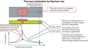
By keeping operating temperatures stable, high thermal conductivity preserves consistent light output and extends the overall lifespan of LED spotlights. It also removes the need for bulky external heat sinks, making spotlight assembly simpler and more compact without losing cooling efficiency.

Why Do LED Spotlight Failures Tie Back to Poor Aluminum PCB Thermal Performance?

Most LED spotlight failures stem from unmanaged heat, and low-quality LED spotlight aluminum PCB is the root cause. LEDs convert 70-80% of energy into heat, and weak thermal conductivity traps this heat, pushing LED chip junction temps over the safe 85°C threshold quickly.

Consistent overheating degrades LED chip performance gradually, causing brightness fade, color shift, and full burnout over time. It also damages internal dielectric layers and circuit traces, leading to short circuits and sudden, unplanned spotlight failures.

Long-term heat stress warps thin or low-grade aluminum substrates, shifting optical lenses and LED chips to ruin beam alignment. This chain of damage drastically shortens spotlight lifespan and raises field failure rates, directly hurting product reliability.

What Thermal Conductivity Standards Work Best for Commercial LED Spotlights?

Commercial Spotlight TypeRecommended Thermal Conductivity (W/mK)Applicable Industry ScenariosCore Performance & Compliance
Low-Power Retail & Display Spotlights1.0 – 2.0Retail shelves, indoor display cabinets, hotel ambient lightingIPC-6012 certified; steady low-heat dissipation, consistent soft brightness, no hotspots
Medium-Power Architectural Accent Spotlights2.0 – 3.0Building facades, gallery accent lighting, restaurant feature lightingBalanced thermal control, stable beam alignment, resists thermal warping, long operational life
High-Power Commercial & Industrial Spotlights3.0 – 5.0Warehouses, outdoor commercial areas, exhibition high-brightness lightingRapid heavy heat dissipation, lowers LED junction temp by up to 28°C, cuts failure rates by 75%

How Does Aluminum PCB Design Impact LED Spotlight Beam Alignment & No Offset?

Beam alignment and zero light offset are critical for consistent, high-quality LED spotlight performance, and every detail of LED Spotlight Aluminum PCB design directly shapes these optical outcomes. Poor design choices cause unwanted beam shift, uneven light distribution, and off-center illumination, while precision-engineered PCB design locks in stable beam angle and eliminates offset for long-term reliable performance. Below are the key design factors that drive beam alignment.

  • Precision LED mounting pad positioning with tight ±0.05mm tolerance ensures accurate chip placement, matching the optical lens center perfectly to avoid initial beam offset.
  • Symmetric PCB substrate layout distributes weight and heat evenly, preventing one-sided warping that tilts LED chips and shifts the beam path.
  • Fixed, standardized lens holder mounting holes on the PCB maintain consistent lens-to-LED distance, avoiding height gaps that cause misaligned light projection.
  • Rigid substrate thickness (1.0–2.0mm for most spotlights) resists thermal warping under continuous operation, keeping optical components aligned without shifting.
  • Uniform copper trace layout avoids uneven heat concentration, preventing localized substrate bending that distorts beam direction over time.
  • Optimized LED array spacing and arrangement align with the designed beam angle, ensuring light overlaps evenly and eliminates off-center bright spots.
  • Flat, smooth substrate surface finish with zero bow or twist guarantees flush mounting of LED and optical parts, eliminating tilt-related beam offset.
  • Matched thermal expansion coefficient between aluminum base and dielectric layer prevents layer separation and substrate distortion during heating and cooling cycles.
  • Clear, accurate alignment markers on the PCB streamline assembly, reducing human error during component installation and ensuring consistent beam alignment across all units.
How Does Aluminum PCB Design Impact LED Spotlight Beam Alignment & No Offset, https://www.bestpcbs.com/blog/2026/03/led-spotlight-aluminum-pcb/

How to Test Aluminum PCB Thermal Efficiency for LED Spotlight Quality Control?

Thermal efficiency testing of LED Spotlight Aluminum PCB is a critical quality control step to verify heat dissipation performance, prevent LED overheating, and ensure long-term spotlight reliability. These tests cover lab-grade precision measurement, production-line quick screening, and long-term reliability validation, with clear, actionable methods for both small-batch sampling and mass production inspection.

  • Conduct infrared thermal imaging scanning under rated operating conditions to map surface temperature distribution and locate hotspots, ensuring no localized temperature exceeds the safe 85°C LED junction temperature threshold.
  • Perform thermal resistance testing per ASTM D5470 standard to measure heat transfer efficiency from LED mounting pads to the aluminum substrate base, a core metric for quantifying thermal conductivity performance.
  • Use laser flash analysis (ASTM E1461) to test bulk thermal conductivity of the aluminum base and dielectric layer, validating material consistency with stated specification values.
  • Run steady-state temperature testing: power the PCB with rated LED load, hold for 60 minutes until temperature stabilizes, and record temperature difference between LED chips and substrate surface.
  • Carry out transient thermal response testing to measure how quickly heat is pulled away from LED chips when powered on, confirming fast heat dissipation at startup.
  • Perform thermal cycling testing (-40°C to 125°C) to simulate extreme temperature changes, checking for thermal performance degradation or substrate warping after repeated cycles.
  • Conduct 168-hour continuous aging test at rated current to monitor temperature stability and ensure no gradual rise in operating temperature over extended use.
  • Test thermal consistency across production batches to confirm uniform heat dissipation performance, avoiding performance gaps between different PCB units.
  • Verify heat dissipation under simulated real-world conditions (with matching heat sink and enclosure) to replicate actual spotlight usage and validate practical thermal efficiency.

How to Balance Cost & Performance When Sourcing LED Spotlight Aluminum PCBs?

Balancing cost and performance when sourcing LED Spotlight Aluminum PCB means avoiding overpaying for unused specs while refusing low-grade materials that cause product failures and lost revenue. It focuses on smart specification matching, reliable supplier selection, and long-term value over short-term upfront savings, directly protecting your production efficiency and end-product quality.

  • Match thermal conductivity and substrate thickness precisely to your LED spotlight’s power rating and application, eliminating over-specified, high-cost features that deliver no real performance gain.
  • Prioritize suppliers with consistent batch quality and strict QC processes, like EBest, to reduce defective PCB rates and avoid costly production downtime and rework.
  • Choose standard aluminum alloy grades (5052/6061) for mainstream spotlights instead of rare, high-cost alloys, as these standard grades meet industry performance needs at a lower cost.
  • Optimize for moderate dielectric layer specifications that meet thermal and insulation requirements, avoiding premium ultra-thin dielectric layers unless needed for high-power models.
  • Order prototype PCBs for performance testing before full bulk orders, verifying thermal stability and optical compatibility to prevent mass production losses from mismatched parts.
  • Negotiate bulk pricing with a long-term reliable supplier instead of switching to low-cost unvetted suppliers, ensuring stable supply and consistent quality without hidden quality risks.
  • Avoid excessive customization on standard spotlight models; limit custom circuit layout and hole design only to specialized, high-value spotlight products.
  • Evaluate total lifecycle value instead of just upfront unit cost, as high-quality PCBs reduce field failures, maintenance, and replacement costs over the product’s lifespan.
How to Balance Cost & Performance When Sourcing LED Spotlight Aluminum PCBs, https://www.bestpcbs.com/blog/2026/03/led-spotlight-aluminum-pcb/

FAQ About LED Spotlight Aluminum PCBs

Q1: What is the core difference between a standard PCB and an LED Spotlight Aluminum PCB?
A1: A standard PCB is typically FR-4 fiberglass with thermal conductivity of just 0.2–0.3 W/mK, offering almost no heat dissipation, while an LED spotlight aluminum PCB has a 3-layer structure (copper circuit layer, thermally conductive dielectric layer, 5052/6061 aluminum base) with 1.0–5.0 W/mK thermal conductivity. This aluminum core design pulls heat away from LED chips 10–15x faster than standard PCBs, making it mandatory for heat-sensitive LED spotlight operation.

Q2: How does thermal conductivity affect LED spotlight lifespan and performance?
A2: Higher thermal conductivity directly lowers LED junction temperature; every 10°C reduction in junction temperature doubles LED lifespan. For LED spotlights, a PCB with 3.0–5.0 W/mK thermal conductivity cuts junction temperature by up to 28°C compared to low-conductivity models, stopping light fade, color shift, and premature chip burnout, and extending total spotlight service life by 60% or more.

Q3: Can a custom LED Spotlight Aluminum PCB fix beam offset and focus issues?
A3: Yes, a custom LED spotlight aluminum PCB eliminates beam offset and focus drift completely. Custom designs include ±0.05mm tolerance LED mounting pads, symmetric substrate layout, fixed lens holder holes, and 1.0–2.0mm rigid warp-resistant thickness, ensuring permanent alignment of LED chips and optical lenses, even under long-term thermal stress and continuous operation.

Q4: Are all aluminum substrates suitable for high-power LED spotlights?
A4: No, only high-grade, thermally optimized 5052/6061 aluminum alloys with stable thermal conductivity and matched thermal expansion coefficients work for high-power (≄30W) LED spotlights. Low-grade recycled aluminum or non-specified alloys have uneven heat distribution, poor thermal stability, and high warpage risk, failing to dissipate heavy heat loads and causing rapid component failure.

Q5: How can I ensure the LED Spotlight Aluminum PCB I source meets quality standards?
A5: Verify three key points: first, request ASTM D5470 thermal resistance test reports and IPC-6012 certification; second, order prototype samples for infrared thermal imaging and 168-hour aging testing; third, partner with a specialized manufacturer like EBest that provides full batch QC records and material certification, ensuring consistent performance and compliance with industry standards.

Order Your LED Spotlight Aluminum PCB from EBest Today

EBest specializes in high-performance LED Spotlight Aluminum PCB, designed to solve thermal, optical, and durability challenges for all LED spotlight applications. Whether you need standard or custom PCBs, we deliver reliable, high-quality products tailored to your needs.

Place your order or request a custom quote today by contacting us at sales@bestpcbs.com — our team is ready to support your LED lighting production needs with expert service and top-tier products.

You may also like

Outdoor LED Display Aluminum PCB – High Thermal for Waterproof Use

March 23rd, 2026

An Outdoor LED Display Aluminum PCB is used because it moves heat away faster, supports stable mounting, and helps the display hold brightness and color consistency over time. This article explains how to choose, design, and source the right Outdoor LED Display Aluminum PCB for waterproof applications. It covers board structure, thermal path design, waterproof strategy, reliability control, application examples, qualification points, and the service strengths of EBest Circuit (Best Technology).

EBest Circuit (Best Technology) is a professional manufacturer of Outdoor LED Display Aluminum PCB, with strong experience in waterproof, UV-resistant, and high-thermal aluminum PCB solutions for outdoor display applications. We help customers solve common issues such as short circuits, aging, uneven heat dissipation, black spots, and brightness decay under harsh outdoor conditions. Our team focuses on reliable thermal performance, structural fit, and stable quality, so customers can achieve more stable results in outdoor environments. We also support projects that need a good balance of reliability, qualification, and long-term supply stability. For Outdoor LED Display Aluminum PCB inquiries, please call +86-755-2909-1601.

Outdoor LED Display Aluminum PCB

Why Choose a Proven Outdoor LED Display Aluminum PCB Partner for Stable Waterproof Performance?

If you are sourcing Outdoor LED Display Aluminum PCB products, the right supplier should deliver more than bare fabrication. You need a partner that understands thermal structure, outdoor sealing, solder joint fatigue, uniformity control, and volume consistency.

EBest Circuit (Best Technology) supplies Outdoor LED Display Aluminum PCB solutions for demanding outdoor use. We support prototyping and production with engineering review, stack-up recommendation, DFM feedback, process alignment, and fast response for display projects that need both heat control and weather resistance.

Core parameters customers usually care about

  • Base material: aluminum metal core
  • Typical structure: copper circuit layer + dielectric + aluminum base
  • Typical board type: single-sided aluminum PCB, with selected hybrid structures when needed
  • Focus points: thermal transfer, flatness, solderability, outdoor durability, consistency
  • Typical applications: billboards, transportation displays, stadium screens, building media walls

Why many buyers shortlist us

  • Quality: controlled fabrication and inspection flow for LED metal core boards
  • Lead time: responsive engineering support for urgent display programs
  • Service: technical communication that goes beyond simple quoting
  • Supply continuity: support for repeatable production and project follow-up

Therefore, the best supplier for this category is not just a board maker but a thermal and reliability partner. In practice, that directly affects brightness stability, installation life, and field maintenance frequency.

Outdoor LED Display Aluminum PCB

What Is an Outdoor LED Display Aluminum PCB and Why Is It Better for Waterproof Use?

An Outdoor LED Display Aluminum PCB is a metal-core circuit board built for LED systems that must run at higher current density and survive outdoor exposure. Its aluminum base spreads heat away from LEDs and driver-related hot zones much more effectively than standard glass-fiber boards in the same use case.

For outdoor display service, the board is only one part of the protection chain, but it is a critical one. It supports thermal control, mechanical rigidity, and better long-term dimensional stability in assemblies that operate in sun, rain, dust, and humidity.

Basic structure

  • Copper layer: carries current and LED interconnect routing
  • Dielectric layer: provides electrical insulation while passing heat downward
  • Aluminum base: spreads heat into the housing or thermal structure

Why this matters outdoors

  • Lower hotspot accumulation
  • Better support for high-brightness duty
  • Improved mechanical support for module installation
  • Better match for thermal management assemblies

As a result, Aluminum PCB for Outdoor LED Display projects usually deliver a more stable operating platform than ordinary FR4-only designs. From an engineering perspective, that stability is what turns a bright screen into a durable outdoor product.

Why Does Aluminum PCB Matter So Much in Outdoor LED Display Thermal Design?

The short answer is heat. Outdoor displays operate under sunlight, high ambient temperature, dense LED placement, and long daily runtime. If heat is not moved away quickly, brightness drops, color shifts increase, and solder joints age faster.

In many outdoor LED systems, thermal load is not just generated by the LEDs themselves. Driver devices, current distribution, enclosure heat buildup, and limited airflow can raise the entire module temperature. That is why the thermal path must be planned as a full system, not just as a board material choice.

Where the heat goes

  • LED junction generates heat
  • Heat passes through solder and copper pad
  • Heat crosses the dielectric layer
  • Aluminum base spreads heat laterally
  • Heat transfers into the module frame or heat-dissipation structure

What a good thermal design improves

  • Brightness retention
  • LED lifetime consistency
  • Solder joint reliability
  • Color uniformity across the panel
  • Reduced risk of local overheating

In real-world applications, thermal performance is the first reason buyers move from standard PCB concepts to Outdoor Aluminum PCB LED Display structures. Overall, better heat flow means better visual stability and lower field failure pressure.

How Is an Outdoor LED Display Aluminum PCB Built for Heat Transfer and Mechanical Strength?

The board is usually built as a layered thermal structure rather than a standard multilayer logic board. The goal is to keep electrical routing simple and the thermal route short, direct, and repeatable.

Most outdoor display aluminum boards use a copper circuit layer on top, a thermally conductive dielectric in the middle, and an aluminum base underneath. The exact dielectric choice matters because it must balance insulation and heat transfer while surviving assembly heat and outdoor service stress.

Typical design considerations

  • Copper thickness: chosen to handle current and voltage drop
  • Dielectric performance: important for thermal resistance and insulation reliability
  • Aluminum thickness: affects stiffness and heat spreading
  • Board flatness: important for LED placement and waterproof mechanical fit

Mechanical advantages

  • Higher rigidity than very thin conventional boards
  • Better support for module fastening
  • Reduced deformation risk during installation
  • Improved contact with metal housings or thermal interfaces

In short, a good LED Display Outdoor Aluminum PCB is both a circuit carrier and a thermal-mechanical platform. Notably, that dual role is one reason it remains the preferred base for high-output outdoor LED modules.

How Does Waterproof Design Work in PCB Aluminum for Outdoor LED Display?

A waterproof outdoor display is never achieved by the PCB alone. It comes from a complete sealing system that includes the board surface, LED package area, connectors, cable exits, gasket interfaces, screws, rear cover, and enclosure design.

The aluminum PCB still plays an important role because its rigidity and thermal behavior support a more stable assembly. However, rain resistance, dust protection, and moisture control depend on system-level integration.

Main waterproof design elements

  • Protective mask and controlled surface finish compatibility
  • Sealant-compatible module edges
  • Waterproof connectors and cable entry control
  • Rear cover sealing and vent planning
  • Conformal protection where the design requires it
  • Drain path planning to avoid trapped water
Design AreaWhat It Must ControlWhy It Matters
PCB surface protectionMoisture, contamination, corrosionProtects conductive features and solder joints
LED and component interfaceSeal continuity and material compatibilityPrevents moisture ingress near active parts
Connector areaWater entry through wiring pathsCommon field failure point
Cabinet interfaceRain splash, dust, temperature cyclingDefines long-term outdoor sealing stability
Drainage and ventingCondensation and trapped moistureReduces hidden water accumulation

This means, a robust PCB Aluminum for Outdoor LED Display design should be reviewed as a full outdoor module system. To sum up, the best waterproof result comes from sealing, drainage, coating, and thermal design working together.

What IP Level Is Common for Outdoor LED Aluminum PCB Display Systems?

For most outdoor screen modules, buyers usually expect front-side protection around IP65 or above, while rear-side protection depends on cabinet structure and installation conditions. The actual target should match the use environment, service method, and enclosure design.

In practical sourcing, it is a mistake to ask only whether the board is waterproof. The better question is whether the entire Outdoor LED Aluminum PCB Display module is engineered to meet its intended outdoor protection level in real installation conditions.

How to interpret the protection need

  • Front side: exposed to rain, dust, washing, and wind-driven water
  • Rear side: depends on enclosure type and site exposure
  • Connector area: often needs separate protection review
  • Maintenance style: front service and rear service affect sealing design
Outdoor ConditionTypical Protection ExpectationDesign Priority
Urban billboardHigh front-side weather resistanceRain sealing and heat management
Building facadeStable front protection with controlled rear areaModule sealing and cable entry control
Coastal installationHigher corrosion resistance focusAnti-moisture and anti-salt strategy
Harsh climate zoneEnhanced sealing and thermal marginCondensation control and reliability reserve

From an engineering perspective, protection level should be defined by the installation scenario, not by marketing language alone. In practice, that is how a sourcing team avoids under-designed outdoor modules.

How Does Outdoor Heat, Rain, Dust, and Humidity Damage LED Display Boards?

Outdoor LED boards do not fail from one cause only. Real failures often come from combined stress such as heat plus humidity, rain plus poor sealing, or thermal cycling plus weak solder joints. That is why reliability planning must be multidisciplinary from the start.

Heat can reduce brightness stability and accelerate aging. Moisture can trigger corrosion, leakage, and intermittent faults. Dust reduces heat release efficiency. Salt and pollution make corrosion more aggressive in coastal or industrial environments.

Common field risks

  • Brightness drop under high temperature
  • Color inconsistency after long operation
  • Dead pixels caused by thermal fatigue or moisture damage
  • Corrosion on exposed conductive areas
  • Short circuit risk from water ingress or condensation
  • Mechanical stress from daily temperature swings

What reliable designs do differently

  • Build thermal margin into the board and housing
  • Protect vulnerable regions from moisture entry
  • Control contaminants during fabrication and assembly
  • Validate the module under realistic outdoor conditions

Overall, outdoor reliability depends on preventing compound failure modes rather than fixing one issue in isolation. Therefore, a serious Outdoor LED Display Aluminum PCB program should always include both thermal and environmental validation.

Why Do Buyers Often Ask About User Pain Points Before Ordering Outdoor LED Display Aluminum PCB?

Because the same problems appear again and again in outdoor LED projects. Buyers want to avoid screens that run too hot, fail after rain, show uneven brightness, or become difficult to maintain after installation. Those concerns are far more common than abstract material questions.

Across public discussions and application-focused content, the recurring pain points are clear: sealing confidence, real thermal performance, corrosion resistance, long-term uniformity, and the gap between quoted spec and field behavior.

Typical buyer pain points

  • Not sure whether the board can support high brightness continuously
  • Concern about rain, condensation, and seal aging
  • Worry about dead pixels and solder fatigue after thermal cycling
  • Need stable quality across repeat orders
  • Need engineering support instead of quote-only communication
  • Want simpler sourcing with a responsive manufacturer

How EBest Circuit (Best Technology) addresses them

  • Engineering-first review for thermal path and manufacturability
  • Clear communication on board structure and application fit
  • Process control for repeatable quality
  • Support for outdoor-use reliability expectations
  • Responsive service for prototype and production stages

Notably, buyers usually stay with suppliers who reduce technical uncertainty early. As a result, choosing a supplier that understands real field pain points can shorten development cycles and improve launch confidence.

What Services and Certifications Should You Expect from an Outdoor LED Display Aluminum PCB Supplier?

A credible supplier should offer more than fabrication capacity. For this product category, you should expect engineering support, manufacturability review, stable process execution, inspection discipline, and documented quality systems.

EBest Circuit (Best Technology) supports customers with LED PCB manufacturing and technical communication for outdoor applications. Buyers also look for certificate visibility because it shows the factory operates with formalized systems rather than informal process control.

Service scope you should expect

  • Engineering review for structure and manufacturability
  • Prototype support for fast verification
  • Production support for volume continuity
  • Inspection control for board consistency
  • Technical communication through project follow-up
CategoryWhat It ShowsWhy It Helps Buyers
Quality management certificationControlled documented processesImproves confidence in repeat production
Environmental compliance supportMaterial and process conformity awarenessHelps global sourcing coordination
Manufacturing process disciplineInspection and control checkpointsReduces variation risk
Engineering support capabilityProblem-solving before productionImproves project efficiency

In real-world sourcing, certifications do not replace engineering capability, but they do strengthen trust. In short, the best supplier combines documented quality systems with practical LED thermal know-how.

What Design Rules Improve Manufacturability for Aluminum PCB for Outdoor LED Display?

A board can look good in layout software and still perform poorly in manufacturing or field service. Good manufacturability means the design is easy to fabricate, easy to assemble, thermally balanced, and stable during long-term use.

For Aluminum PCB for Outdoor LED Display products, manufacturability is especially important because LED arrays expose every inconsistency. Uneven pad design, copper imbalance, poor spacing decisions, and weak mechanical planning can all show up later as visible display defects.

Important design priorities

  • Keep thermal paths short and direct
  • Use balanced pad and copper planning for uniform heat spread
  • Maintain good spacing for assembly quality and contamination control
  • Consider flatness and module mounting from the start
  • Match connectors and sealing features to service conditions
  • Review current carrying capacity, not just routing completion

Typical DFM review points

Review PointWhy It MattersImpact on Outdoor Use
Pad design consistencyImproves solder qualityReduces uneven optical performance
Copper distributionSupports heat spread and flatnessImproves stability under thermal load
Mounting hole strategyProtects board integrityHelps cabinet integration
Surface protection compatibilitySupports coating and sealingImproves weather durability

This means, manufacturability is not separate from reliability in outdoor LED boards. From an engineering perspective, good DFM choices reduce both process risk and field repair pressure.

How Does Outdoor LED Display Aluminum PCB Compare with FR4 for High-Brightness Screens?

For low-power electronics, FR4 is a proven standard material. For outdoor high-brightness LED display boards, aluminum-based structures are often the better fit because they handle heat spreading and mechanical support more effectively.

The decision is not about one material being universally better. It is about matching the substrate to the thermal load, brightness target, operating environment, and service expectations of the final product.

ItemOutdoor LED Display Aluminum PCBFR4 PCB
Heat dissipationStrong heat spreading through metal baseMuch lower thermal conduction in standard form
Mechanical rigidityGood structural support for LED modulesDepends on thickness and support design
Outdoor high-brightness suitabilityVery suitableLimited for thermally stressed designs
Thermal path simplicityDirect and efficientOften needs extra thermal measures
Typical use focusLED lighting and display modulesGeneral electronics and control circuits

Overall, aluminum becomes the practical choice when heat and outdoor duty cycle drive the design. Therefore, many high-output display projects move to Outdoor LED Display Aluminum PCB when they need stronger thermal margin.

Outdoor LED Display Aluminum PCB

How Is an Outdoor Aluminum PCB LED Display Project Manufactured Step by Step?

The manufacturing route must protect both electrical quality and thermal integrity. Unlike a generic board flow, an outdoor LED metal-core board needs tighter attention to dielectric handling, surface consistency, routing quality, and final flatness.

A stable process also helps later waterproof assembly because a well-controlled board fits more predictably into module housings, gaskets, and sealed mechanical structures.

Typical process flow

  • Engineering file review and manufacturability confirmation
  • Material preparation and metal-core laminate selection
  • Circuit imaging and etching
  • Drilling, routing, and profile control
  • Solder mask and surface finish processing
  • Dimensional, appearance, and electrical inspection
  • Packing and shipment control for board protection

What the factory must watch closely

  • Dielectric integrity
  • Trace and pad precision
  • Board flatness
  • Surface cleanliness
  • Edge quality for later sealing and assembly

As a result, production quality on this board type is tightly linked to final display reliability. Notably, buyers who review process discipline early usually avoid many later installation issues.

What Four Industries Commonly Use LED Display Outdoor Aluminum PCB Solutions?

The most active sectors are those that need high brightness, reliable outdoor visibility, and long operating hours. In these applications, the board must support stable light output while tolerating weather and installation stress.

1. Outdoor advertising and media

Large billboards and building screens need stable brightness, color consistency, and low maintenance pressure. The LED Display Outdoor Aluminum PCB helps manage thermal load in dense, high-visibility installations.

2. Transportation and traffic information

Roadside information boards, station displays, and public guidance systems need dependable operation in changing weather. Good thermal design and sealing reduce service interruptions.

3. Stadium and event screens

These projects face strong daylight, long runtime, and visibility demands. Board stability matters because hot spots and module inconsistency quickly become visible on large display surfaces.

4. Retail facade and commercial exterior signage

Exterior brand displays need slim structures, stable brightness, and attractive long-term appearance. Aluminum PCB solutions help balance compact design with thermal control.

IndustryMain NeedWhy Aluminum PCB Helps
AdvertisingLong runtime and brightness stabilityBetter heat handling for continuous operation
TransportationOutdoor reliabilitySupports stable thermal and mechanical performance
StadiumsHigh visual consistencyReduces thermal unevenness across modules
Retail exteriorsCompact structure and weather resistanceImproves heat spread in limited space

In practice, these industries choose aluminum boards because visibility and uptime are directly linked to revenue or public function. To sum up, the board is not just a material choice but a performance enabler for outdoor display systems.

How Should You Evaluate a Supplier Before Ordering Outdoor LED Display Aluminum PCB?

Before placing an order, look at engineering fit, process stability, communication quality, and repeatability. A visually attractive quote means little if the supplier cannot explain thermal structure, protection strategy, and application compatibility.

Useful evaluation questions

  • Do they understand outdoor display thermal paths?
  • Can they discuss dielectric and aluminum structure clearly?
  • Do they review manufacturability before production?
  • Can they support repeat orders with stable quality?
  • Do they communicate clearly on lead time and project status?
  • Can they align the board with your module and enclosure strategy?

Green flags in supplier communication

  • They ask about brightness, environment, and service conditions
  • They review drawings instead of quoting blindly
  • They discuss reliability, not only board thickness
  • They show an organized approach to quality documentation

This means, a good supplier reduces project risk before production begins. Overall, the best sourcing decision comes from technical clarity, not from generic product language.

Why Choose EBest Circuit (Best Technology) for Outdoor LED Display Aluminum PCB Orders?

If your project needs a reliable Outdoor LED Display Aluminum PCB, EBest Circuit (Best Technology) can support you with practical engineering communication and production-oriented service. We understand that outdoor LED boards must balance heat transfer, structural fit, manufacturability, and long-term use stability.

We work with customers who need more than a standard board quote. Our goal is to help you move from concept to repeatable production with clearer technical decisions, better fit for outdoor applications, and smoother project follow-up.

What we offer for this product type

  • Outdoor LED aluminum PCB support for display-related applications
  • Engineering review before production
  • Responsive communication during project execution
  • Prototype to production support for ongoing programs
  • Quality-focused process control for stable repeat orders

If you are looking for a dependable source for Aluminum PCB for Outdoor LED Display products, EBest Circuit (Best Technology) is ready to support your order. Please send your project files and inquiry to sales@bestpcbs.com.

Therefore, choosing the right partner helps you improve both product confidence and sourcing efficiency. In real-world applications, that can make a visible difference in launch speed and long-term display stability.

FAQs About Outdoor LED Display Aluminum PCB

Why is Outdoor Aluminum PCB LED Display better than standard FR4 in high-brightness use?

Because outdoor screens usually run hotter and longer. Aluminum-based boards spread heat more effectively, which makes them better suited to high-output LED modules exposed to sunlight and changing ambient temperature.

What industries most often use Outdoor LED Aluminum PCB Display products?

The most common industries are outdoor advertising, transportation displays, stadium screens, and exterior commercial signage. These sectors need stable brightness, weather resistance, and long operating life.

How do aluminum PCBs protect outdoor LED signs from extreme weather?

Beyond heat dissipation, aluminum provides high dimensional stability and mechanical durability. Outdoor displays face extreme temperature fluctuations (from freezing nights to scorching days) which can cause standard boards to warp or crack. Aluminum has a lower coefficient of thermal expansion than FR4, meaning the board maintains its shape better. Additionally, most outdoor aluminum PCBs receive specialized surface treatments like anodizing or polyurethane coating to provide a robust barrier against moisture, salt spray, and UV-induced corrosion.

What are the design limitations of using aluminum PCBs for LED modules?

The main trade-off for the thermal benefits of aluminum is limited circuit complexity. Because the base is a conductive metal, aluminum PCBs are typically restricted to single-layer or simple double-layer designs. Creating multilayer stacks is significantly more expensive and technically difficult compared to FR4. Designers must also account for:

  • Rigidity: Aluminum cannot be used for curved or flexible display designs.
  • Component Mounting: Only Surface Mount Technology (SMT) is practical; Through-Hole Technology (THT) is generally not possible because the metal base would short the component leads.

Why order Outdoor LED Display Aluminum PCB from EBest Circuit (Best Technology)?

Because we provide product support with practical engineering communication, quality-focused manufacturing control, and responsive service for outdoor LED projects. If you need Outdoor LED Display Aluminum PCB products, contact sales@bestpcbs.com to discuss your order.

You may also like

LED Grow Light Aluminum PCB – High Thermal Conductivity for Plant Growth

March 23rd, 2026

LED Grow Light Aluminum PCB is a metal-core printed circuit board designed for grow lighting systems, using an aluminum base to improve heat dissipation, support high-density LED layout, and ensure stable long-term lighting performance. This article explains how LED Grow Light Aluminum PCB designs work, what parameters matter before production, how to improve thermal reliability, and how to choose the right manufacturing partner for custom projects.

EBest Circuit (Best Technology) is a professional LED Grow Light Aluminum PCB manufacturer with solid experience in thermal design, spectrum-compatible PCB structure, and stable production for plant lighting applications. We understand that grow light projects are not only about making a board, but about balancing heat dissipation, spectrum layout compatibility, structural reliability, and long-term operating stability in real working conditions. For customers who care about thermal consistency, optical adaptation, scalable supply, and dependable long-run performance, we provide practical engineering support from PCB design review to manufacturing execution. Whether your focus is product quality, thermal efficiency, structural matching, or batch supply capability, our team can help turn your grow light concept into a production-ready and reliable solution. Pls feel free to contact us anytime at +86-755-2909-1601 to discuss your LED Grow Light Aluminum PCB project.

LED Grow Light Aluminum PCB

What Is LED Grow Light Aluminum PCB and Why Is It Common in Plant Lighting?

LED Grow Light Aluminum PCB is a metal-core circuit board built with an aluminum base to improve heat dissipation for LED lighting applications. In plant lighting, it is commonly used because the board must support continuous operation, high LED density, and stable junction temperature under demanding daily use.

Compared with a standard board, an aluminum-based structure moves heat away from the LED package more efficiently. That helps reduce thermal accumulation and supports more consistent optical and electrical performance across the board.

Why it is widely used in grow lights

  • Supports high-power and medium-power LED arrays
  • Improves thermal spreading across long bars and panel boards
  • Provides good mechanical support for thin or extended fixtures
  • Works well in linear, strip, round, and custom fixture designs

For many horticulture products, the board is not just a substrate. It is a thermal platform. That is why board selection has a direct effect on performance and service life.

Notably, aluminum PCB is common in grow lights because thermal control and structural stability matter every day of operation. To sum up, it offers a practical foundation for reliable LED plant-lighting assemblies.

Why Is Aluminum PCB Better Than Standard FR4 for Grow Light Applications?

For most grow-light boards, aluminum is preferred because the job is thermal before it is decorative. Standard FR4 can still work in lower-power designs, but once LED density rises, heat becomes harder to spread and remove. That is where aluminum PCB offers a clear advantage.

Aluminum PCB versus FR4 for grow light products

ItemAluminum PCBFR4 PCB
Heat dissipationStrongModerate
RigidityHigherModerate
LED density fitBetterLimited
Heatsink couplingDirectIndirect
Typical useLight engineControl board
Long-run stabilityBetterLower

This does not mean FR4 has no place. In many fixtures, the driver or control section can still use FR4, while the LED light board uses aluminum. That mixed approach is practical when each board has a different job.

As a result, aluminum PCB is usually the better fit when the LED board carries the real thermal load. From a product standpoint, that helps keep the fixture more stable during sustained use.

How Is an Aluminum PCB LED Grow Light Board Structured?

The structure of an Aluminum PCB LED Grow Light board is simple in appearance but important in function. A typical board contains a copper circuit layer, a thermally conductive dielectric layer, and an aluminum base. These layers work together to carry current, insulate electrically, and move heat downward into the metal substrate.

Main layers in a typical grow light aluminum PCB

  • Copper circuit layer for electrical routing and LED pad connection
  • Thermal dielectric layer for electrical isolation with heat transfer capability
  • Aluminum base layer for heat spreading and structural support

Optional design elements

  • Solder mask and legend
  • Reflective white surface for light efficiency in some designs
  • Mounting holes for direct heatsink fastening
  • Connector areas for modular assembly
  • Custom outline for bars, rings, panels, or segmented boards

Good structure selection is not only about thermal conductivity. It is also about assembly compatibility, flatness, and whether the board fits the mechanical design of the final lamp.

In real-world applications, the board stack directly shapes thermal behavior and assembly stability. Therefore, the structure should always be chosen with the final fixture in mind.

Why More Buyers Start with the Right LED Grow Light Aluminum PCB Partner?

If your end product depends on stable brightness, even heat spreading, and repeatable assembly, your supplier choice affects the result from the first file review. A capable manufacturer does more than make a board. They check thermal paths, pad geometry, current load, soldering windows, and the match between board design and final fixture structure.

That matters even more in plant lighting. These products often run for long daily cycles, use dense LED arrays, and work in warm or humid environments. A weak board design can lead to hot spots, color shift, shortened LED life, or uneven performance across the fixture.

What you should expect before placing an order

  • Core parameter review including board size, aluminum thickness, copper weight, thermal dielectric, voltage, current, LED count, and mounting method
  • DFM support to improve manufacturability before tooling starts
  • Assembly compatibility checks for SMT process, reflow profile, connector fit, and final heatsink attachment
  • Project communication that is fast, clear, and technical enough to solve issues early

If you are sourcing PCB Aluminum LED Grow Light products for a new or ongoing project, EBest Circuit (Best Technology) can support fabrication, assembly, and engineering review in one workflow. Send your files to sales@bestpcbs.com for a technical evaluation and production support.

Therefore, a strong supplier reduces redesign risk before the first batch starts. In practice, that improves manufacturability, thermal stability, and delivery confidence at the same time.

Why Choose Us for LED Grow Light Aluminum PCB?

Buyers do not only compare boards. They compare consistency, response speed, process control, and whether a supplier can support real production conditions. For LED Grow Light Aluminum PCB projects, the most important value usually comes from thermal design awareness, assembly experience, and supply continuity.

Why customers choose EBest Circuit (Best Technology)

  • Quality focus with controlled manufacturing and inspection for aluminum PCB and LED assembly projects
  • Lead time support for samples, pilot runs, and repeat production
  • Engineering service with DFM feedback, stack-up advice, and assembly-oriented review
  • Supply support for PCB fabrication, SMT assembly, and one-stop project coordination
  • Communication efficiency so technical questions are solved quickly instead of being delayed between teams

What this means for your project

A grow light board is not just a lighting PCB. It is part of a full thermal and electrical system. We review the board as a working product, not as an isolated drawing. That helps reduce board warpage risk, poor solder joints, current imbalance, and avoidable layout revisions.

For buyers looking for Light Grow LED Aluminum PCB, Grow Light Aluminum PCB LED, or PCB LED Grow Light Aluminum production support, we can help turn design data into a stable and repeatable build.

Overall, choosing the right manufacturer improves both board performance and project coordination. As a result, the product reaches assembly with fewer unknowns and better long-term consistency.

What Services and Certifications Should a LED Grow Light Aluminum PCB Supplier Have?

A qualified supplier should offer more than bare-board fabrication. For horticulture lighting, it is better to work with a manufacturer that can review the design, build the board, assemble the LEDs, and control traceability during production. That shortens communication loops and helps keep thermal and assembly decisions aligned.

Our service scope and certifications

CategoryDetailsWhy It Matters for LED Grow Light Aluminum PCB
PCB FabricationAluminum PCB, MCPCB, custom board sizes, prototype to productionSupports custom thermal structures and LED board formats
PCBA ServiceLED SMT assembly, connector assembly, functional supportImproves build consistency for populated grow light boards
Engineering SupportDFM review, pad design check, manufacturability adviceHelps prevent rework and process instability
Supply CoordinationOne-stop handling for PCB and assembly workflowReduces handoff issues between multiple vendors
ISO 9001Quality management systemSupports process discipline and documentation control
ISO 13485Medical quality system capabilityShows strong process rigor and traceability awareness
IATF 16949Automotive quality system capabilityReflects high expectations for consistency and process control
AS9100DAerospace quality system capabilityDemonstrates disciplined production management

These capabilities are useful because many grow-light projects move from custom sampling into recurring production. A supplier with stable systems is better prepared for that transition.

From an engineering perspective, service range and quality systems directly affect repeatability. In real-world projects, that means smoother transfer from design files to finished boards.

What Problems Do Buyers Usually Face with LED Grow Light Aluminum PCB Projects and How Do We Solve Them?

Most buyers are not struggling with the basic concept of an aluminum board. They struggle with execution. The common problems are uneven temperature rise, unstable assembly yield, unclear design input, LED mismatch, and uncertainty about how the board will behave once mounted into a real fixture.

Common pain points and our solutions

Pain PointTypical IssueOur Support
Thermal hot spotsUneven heatThermal layout review
Unclear filesMissing notesEarly file check
Assembly instabilitySolder inconsistencyDFM optimization
Custom dimensionsHard to processShape-based planning
Long-run reliabilityPerformance driftStable material choice
Supplier coordinationSlow handoffOne-stop execution

If you are developing a custom Aluminum PCB LED Grow Light product, we can review the files and help convert concept drawings into a production-ready board structure. Orders and technical inquiries can be sent to sales@bestpcbs.com.

In short, most failures come from the gap between design intent and production reality. This means early engineering review is often the fastest way to protect yield and long-term stability.

What Core Parameters Should You Confirm Before Ordering LED Grow Light Aluminum PCB?

Before production starts, buyers should confirm the board parameters that most affect performance and manufacturability. This saves time, reduces back-and-forth, and helps the supplier make the right recommendations from the start.

Key parameters to confirm

  • Board size and shape such as strip, round, square, or custom linear panel
  • Aluminum thickness based on structural and thermal needs
  • Copper thickness based on current load and routing width
  • Dielectric type based on insulation and heat transfer targets
  • LED package and quantity such as mid-power, high-power, or mixed spectrum layout
  • Input voltage and drive method including series-parallel arrangement
  • Mounting method such as screws, adhesive interface, or integrated heatsink contact
  • Environmental expectation including humidity, enclosure style, and operating duration

Why this matters

A board that looks correct on paper may still become difficult to assemble if pad spacing is tight, connector placement is awkward, or the board is too long for stable process handling. Clear data prevents those avoidable issues.

If you need support defining these parameters for Light LED Grow Aluminum PCB or Grow Light LED Aluminum PCB projects, EBest Circuit (Best Technology) can review the requirements before release.

This means better parameter clarity leads to better fabrication and assembly decisions. Overall, early specification control is one of the simplest ways to improve project stability.

How Do Spectrum Design and LED Layout Affect Grow Light Board Performance?

In grow-light products, board design is closely tied to spectrum strategy. The board must physically support the LED mix, spacing, and current distribution needed for plant growth targets. That makes the layout important not only for electrical routing, but also for light uniformity and thermal balance.

What layout decisions usually matter most

  • LED spacing to avoid clustered hot spots and uneven light distribution
  • Mixed wavelength placement for full-spectrum or targeted plant-light recipes
  • Series and parallel planning for current balance and driver compatibility
  • Board length and segmentation for modular fixtures and easier thermal spreading

Common spectrum choices in grow light boards

  • Full-spectrum white combinations for general plant growth
  • Red-enhanced layouts for flowering support
  • Blue-support combinations for vegetative growth and compact morphology
  • Mixed custom arrays for specialized horticulture systems

A good layout should keep electrical performance, thermal behavior, and optical goals aligned. If only one of those is optimized, the final product may still feel unbalanced in real use.

From an application view, smart LED placement improves both board reliability and lighting consistency. Notably, layout quality often decides whether a grow light feels engineered or merely assembled.

LED Grow Light Aluminum PCB

How Do Thermal Design and Assembly Control the Reliability of LED Aluminum PCB Grow Light Products?

Thermal design is one of the biggest factors behind long-term grow-light reliability. Even a good aluminum board will not perform well if the heat path is incomplete. The substrate, copper layout, dielectric, soldering process, and heatsink interface all need to work together.

Thermal and assembly factors that matter most

  • Uniform copper distribution to reduce localized temperature rise
  • Proper LED spacing to avoid thermal crowding
  • Stable reflow profile to protect solder quality and LED integrity
  • Flat board condition for strong contact with the heatsink surface
  • Reliable interface attachment using the right mounting method and contact pressure

Why assembly quality matters

Many field issues do not start from the substrate alone. They start from poor solder joints, uneven contact to the metal body, or layout choices that create current imbalance. A well-built board should be easy to assemble and easy to cool.

At EBest Circuit (Best Technology), we treat LED Grow Light Aluminum PCB products as both a PCB job and an LED assembly job. That approach helps reduce practical risks before the product reaches final housing integration.

In practice, reliability comes from the full thermal path rather than from one material choice alone. As a result, board design and assembly discipline must be developed together.

Which Industries Commonly Use LED Grow Light Aluminum PCB and What Do Real PCB Cases Look Like?

LED Grow Light Aluminum PCB is not limited to one type of customer. The same board technology appears across several controlled-lighting sectors where heat, uniform output, and long runtime matter.

Four common application sectors

IndustryProduct FormPCB NeedTypical Case
Indoor Grow TentsLight bars, panelsTight-space coolingLong bar board
Commercial GreenhousesHigh-output modulesLong-cycle stabilitySegmented board
Vertical FarmingSlim rack lightsUniform outputNarrow custom board
Seedling SystemsCompact light unitsPrecise LED layoutSmall-format board

These cases show that the board is often shaped by the final mechanical and agricultural goal. Some projects need long rigid bars. Others need compact boards with careful spectrum grouping. The board structure should match the use case, not the other way around.

To sum up, aluminum grow-light boards are used wherever stable light output and controlled heat matter. In short, the right PCB structure helps each sector build more reliable lighting platforms.

How Should You Compare Different LED Grow Light Aluminum PCB Design Options?

Not every grow-light board should be designed the same way. The best option depends on power density, fixture geometry, assembly plan, and environmental exposure. A good comparison should focus on the working condition of the product rather than on appearance alone.

Comparison of common design directions

Design TypeBest FitMain StrengthEngineering Focus
Linear aluminum boardGrow bars, racksHeat spreadingFlatness, mounting
Round aluminum boardCompact lampsCenter balanceFootprint control
Segmented panel boardLarge fixturesModularityPanel planning
Mixed-board systemSplit-function productsFlexibilityBoard coordination

For custom projects, the right answer usually comes from the product structure, not from a template. That is why supplier review is valuable before finalizing the design for production.

From a design standpoint, comparing options early prevents unnecessary board revisions later. Therefore, board format selection should always support manufacturability and real application use. Finally, if you are looking for a reliable supplier for LED Grow Light Aluminum PCB products, EBest Circuit (Best Technology) is ready to support your project. For technical review, custom manufacturing, or order inquiries, please contact sales@bestpcbs.com.

LED Grow Light Aluminum PCB

How Can You Start a Custom LED Grow Light Aluminum PCB Project Smoothly?

The smoothest projects start with complete files and a clear target. You do not need every detail finalized, but the more complete the input is, the faster the technical review becomes. This helps the supplier advise on structure, manufacturability, and assembly readiness from the beginning.

Useful files to prepare

  • Gerber files
  • BOM if assembly is required
  • Pick and place file
  • Board drawing or dimension notes
  • Target current, voltage, and LED arrangement details
  • Mechanical notes for heatsink or housing fit

What happens next

After the files are reviewed, the supplier can check manufacturability, identify risks, and recommend suitable board and assembly choices. That shortens decision time and improves build readiness.

EBest Circuit (Best Technology) provides custom LED Grow Light Aluminum PCB fabrication and assembly support. If you need technical review or would like to place an order, pls feel free to contact us via sales@bestpcbs.com.

Overall, a clear project package leads to faster engineering closure and smoother production launch. As a result, the project becomes easier to scale from sample to ongoing build.

FAQs About LED Grow Light Aluminum PCB

Why use Aluminum PCB LED Grow Light boards instead of standard boards?

Because grow lights often run for long periods and generate concentrated heat. Aluminum helps spread that heat more effectively, which supports board reliability and more stable LED operation.

Why does LED Aluminum PCB Grow Light design need thermal review before production?

Because a board can look electrically correct but still create hot spots, poor heatsink contact, or assembly instability. Thermal review helps catch those problems before they become production issues.

How is Aluminum LED Grow Light PCB different from a normal lighting PCB?

It is usually designed for denser LED placement, stronger heat transfer, longer daily runtime, and closer integration with the fixture body used in horticulture products.

Can EBest Circuit support custom PCB LED Grow Light Aluminum projects?

Can EBest Circuit support custom PCB LED Grow Light Aluminum projects? Yes. We provide custom board fabrication, engineering review, and assembly support for LED grow light applications. You can send your inquiry and design files to sales@bestpcbs.com.

How do I order Light Grow LED Aluminum PCB products from EBest Circuit?

Send your Gerber files, board requirements, and project details to sales@bestpcbs.com. Our team can review the design, support production planning, and help you move toward a stable custom build.

You may also like

LED Ceiling Light Aluminum PCB – Thermal Solution for Home Lighting Buyers

March 23rd, 2026

For anyone building, repairing, or sourcing high-performance LED ceiling lights, the right circuit board directly dictates lifespan, brightness, and reliability. A LED ceiling light aluminum PCB solves the core heat-related flaws of standard PCBs, keeping LED chips cool, maintaining consistent light output, and cutting down on premature failures. This guide breaks down everything you need to know about these specialized PCBs, from core specs to real-world use cases, and why EBest is your top source for consistent, high-quality boards.

LED Ceiling Light Aluminum PCB, https://www.bestpcbs.com/blog/2026/03/led-ceiling-light-aluminum-pcb/

What Are the Top Pain Points with Standard PCBs for LED Ceiling Lights?

Most LED ceiling light failures stem from standard FR-4 PCBs that fail to handle heat and long-term use properly. Below are the top 6 common pain points that plague designers, manufacturers, and end users alike, all of which are solved by switching to a dedicated LED ceiling light aluminum PCB.

  • Why do standard PCBs cause severe heat buildup in LED ceiling lights and shorten chip lifespan?
  • How do standard PCBs lead to uneven lighting and visible hotspots across LED ceiling panels?
  • Why do standard fiberglass PCBs warp or delaminate under long-term LED operation?
  • How do standard PCBs trigger early LED burnout and frequent fixture replacements?
  • Why do standard PCBs cause color shifting and inconsistent light output over time?
  • How do standard PCBs lower overall product reliability and increase maintenance costs?

These recurring issues make standard PCBs a poor fit for LED ceiling lighting, as they cannot match the thermal stability and durability of aluminum-based PCBs. Partner with EBest to eliminate these pain points completely with reliable LED ceiling light aluminum PCB solutions.

Our Solutions to Solve the Challenges of LED Ceiling Light Aluminum PCB

Here are our solutions to these pain points of LED ceiling light aluminum PCB:

  • Against severe heat buildup and shortened LED lifespan: Our LED Ceiling Light Aluminum PCB uses a high-thermal-conductivity aluminum base (1.0-4.0 W/(m·K)) that rapidly transfers heat away from LED chips, keeping operating temperatures stable and extending chip service life far beyond standard FR-4 PCB limits.
  • Against uneven lighting and hotspots: The uniform thermal conductivity of our aluminum PCB spreads heat evenly across the entire board surface, eliminating concentrated hotspots and ensuring consistent brightness and light distribution across the whole ceiling light panel.
  • Against warping and delamination: We use a rigid, heavy-duty aluminum substrate paired with a high-temperature resistant insulation layer that withstands long-term heat exposure without warping, bending, or layer separation, maintaining structural integrity for continuous use.
  • Against early LED burnout and frequent replacements: By maintaining consistent, safe operating temperatures and eliminating heat-induced damage, our aluminum PCB drastically reduces LED chip burnout rates, cutting down on fixture replacements and downtime for both manufacturers and end users.
  • Against color shifting and inconsistent light output: Stable thermal performance prevents LED chip degradation and light wavelength shifts, preserving consistent color rendering and brightness levels throughout the lifespan of the ceiling light, with no gradual fading or discoloration.
  • Against low reliability and high maintenance costs: Our durable, heat-stable LED Ceiling Light Aluminum PCB boosts overall fixture reliability, reduces long-term maintenance and repair needs, and lowers total ownership costs while improving product quality and customer satisfaction.

These recurring issues make standard PCBs a poor fit for LED ceiling lighting, as they cannot match the thermal stability and durability of aluminum-based PCBs. Partner with EBest to eliminate these pain points completely with reliable LED ceiling light aluminum PCB solutions.

Why EBest Stands Out for LED Ceiling Light Aluminum PCB Orders?

Here are reasons why EBest stands out for LED ceiling light aluminum PCB orders:

We deliver uncompromising, consistent quality for every LED ceiling light aluminum PCB we manufacture. Every board undergoes full structural and thermal performance checks before shipment, ensuring zero defects and uniform performance across every batch, so your LED ceiling light products maintain stable quality and long-term reliability with no unexpected failures.

We honor reliable, on-time lead times for both small-batch prototype orders and large-scale mass production runs. Our streamlined, efficient production workflow eliminates unnecessary delays and bottlenecks, ensuring you receive your PCB order exactly when you need it to keep your lighting production schedule on track, no last-minute holdups.

Our supply chain is fully vetted and rock-solid, with long-term partnerships with premium raw material suppliers. We source only high-grade aluminum substrates and heat-resistant insulation materials, guaranteeing consistent material quality across all orders and eliminating production disruptions from material shortages or subpar inputs.

We offer full customization flexibility to match your unique LED ceiling light design requirements. From custom board sizes and circuit layouts to tailored thermal conductivity specs and surface finishes, we adjust every detail to fit your fixture housing, LED chip type, and performance needs, no one-size-fits-all limitations.

We provide end-to-end customer support from initial inquiry to post-delivery assistance. Our technical team offers free, practical design guidance to optimize manufacturability and thermal performance, and we provide responsive troubleshooting and assembly support to make your entire sourcing process smooth and low-effort.

As a trusted specialist in LED aluminum PCBs, we focus fully on the lighting industry’s unique needs. We build our products to meet global safety and quality standards, pairing durable, high-performance materials with precise manufacturing to help you create LED ceiling lights that stand out for longevity and consistent performance in the market.

Why EBest Stands Out for LED Ceiling Light Aluminum PCB Orders, https://www.bestpcbs.com/blog/2026/03/led-ceiling-light-aluminum-pcb/

EBest Certifications & Quality Credentials for LED Ceiling Light Aluminum PCB

Our certifications confirm full compliance with global industry standards for PCB manufacturing and LED lighting components, giving you complete confidence in product reliability, safety, and market eligibility. All our LED ceiling light aluminum PCB boards are produced under these certified quality systems, with consistent adherence to every standard.

  • ISO 9001: Validated international quality management system certification, covering our full production, inspection, and quality control processes for LED Ceiling Light Aluminum PCB. This certification ensures strict process standardization and consistent batch quality across all orders.
  • RoHS: Full compliance with EU hazardous substance restriction directives, confirming our LED Ceiling Light Aluminum PCB is free from restricted harmful materials. This makes our boards safe for indoor residential and commercial lighting use, and eligible for sale across EU and global markets.
  • UL Recognized: Certification meeting North American safety and performance standards for printed circuit boards. This credential validates the safety, thermal stability, and operational reliability of our LED Ceiling Light Aluminum PCB for use in the North American lighting market.
  • IPC Class 2/3: Compliance with industry-leading PCB manufacturing and assembly standards. IPC Class 2 suits general commercial LED lighting applications, while Class 3 supports high-reliability, long-performance lighting projects, ensuring our boards meet diverse project quality demands.

Every LED ceiling light aluminum PCB from EBest is manufactured to meet these certified standards, guaranteeing reliable performance, global regulatory compliance, and consistent quality for your lighting products.

How Does a Reliable LED Ceiling Light Aluminum PCB Improve Heat Dissipation?

LED ceiling lights generate consistent heat during operation, and standard FR-4 PCBs act as heat insulators rather than heat conductors, trapping heat close to LED chips and causing long-term damage. A LED ceiling light aluminum PCB fixes this flaw by using a purpose-built three-layer structure designed for efficient, passive heat transfer, moving heat away from sensitive LED components quickly and evenly.

The board consists of a circuit layer for LED mounting, a thin, high-thermal-conductivity dielectric insulation layer, and a solid aluminum base layer. This layered design creates a direct thermal path that standard fiberglass PCBs cannot match, drastically lowering thermal resistance and speeding up heat movement.

Heat generated by LED chips first transfers from the circuit layer through the stable insulation layer to the thick aluminum base. The aluminum base acts as a built-in heat sink, spreading heat across its entire surface to avoid concentrated hotspots, and then releases heat into the surrounding fixture and air.

Unlike standard PCBs that hold heat and drive up operating temperatures, this design maintains lower, consistent temperatures for LED chips. Stable temperatures prevent accelerated light degradation, color shift, and premature burnout, directly extending the overall lifespan and performance consistency of LED ceiling lights.

This passive cooling method requires no extra fans, heat fins, or bulky cooling parts, keeping ceiling light fixtures slim, lightweight, and easy to install for both residential and commercial settings. It also simplifies assembly and reduces overall fixture complexity without sacrificing thermal performance.

What Key Features Define a Reliable LED Ceiling Light Aluminum PCB?

A truly reliable LED ceiling light aluminum PCB stands out through consistent performance, long-term durability, and seamless compatibility with LED lighting systems, with several core features that separate high-quality boards from generic alternatives. These features work together to deliver stable thermal management, dependable operation, and easy assembly, directly boosting the lifespan and performance of finished LED ceiling lights.

First and foremost, targeted thermal conductivity is non-negotiable. A quality aluminum PCB uses a specially formulated aluminum base with balanced thermal transfer capabilities, designed to pull heat away from LED chips quickly without creating uneven hotspots. This targeted heat dissipation keeps LED components at safe operating temperatures during continuous use, preventing light degradation and premature burnout that plague lower-quality boards.

A durable, heat-resistant insulation layer is another critical feature. The insulation layer between the copper circuit layer and aluminum base must withstand high soldering temperatures and long-term heat exposure without peeling, cracking, or losing thermal efficiency. This layer maintains electrical isolation while supporting consistent heat transfer, ensuring the board remains structurally intact even after thousands of hours of operation.

Precise manufacturing and dimensional accuracy also define a reliable board. Every trace, pad, and drill hole must be etched and machined to tight tolerances, ensuring a perfect fit for LED chips, drivers, and fixture housing. Accurate dimensions eliminate assembly issues, poor solder connections, and misalignment that can compromise both performance and safety, making production smoother for lighting manufacturers.

Compliant, reliable surface finishing is equally important. A proper surface finish protects the copper circuitry from oxidation, supports strong solder bonds, and meets global environmental and safety standards for indoor lighting. Lead-free finishes ensure the board is safe for residential and commercial use, while also resisting corrosion and extending shelf life before assembly.

Finally, a reliable aluminum PCB offers consistent batch-to-batch quality, with uniform material composition and performance across every unit. This consistency eliminates variations between individual boards, ensuring every finished LED ceiling light performs the same, with predictable lifespan and light output. Choosing a board with all these features ensures long-term reliability and reduces costly rework or product failures down the line.

How to Choose the Right LED Ceiling Light Aluminum PCB?

Selecting the correct LED Ceiling Light Aluminum PCB requires matching core specifications to your fixture design, LED power, and usage scenario. Follow these clear, actionable guidelines to pick the ideal board for consistent performance and long service life:

  • Match thermal conductivity to LED power level: For high-power LED ceiling lights (above 15W), choose a board with 2.0–4.0 W/(m·K) thermal conductivity for maximum heat dissipation. For low-power residential fixtures, 1.0–1.5 W/(m·K) is sufficient to maintain stable operating temperatures.
  • Select board thickness for fixture fit: Stick to 1.0mm–1.6mm thickness for most standard slim ceiling light housings to ensure a clean, proper fit. Use thicker boards (1.8mm–2.0mm) for heavy-duty or larger commercial fixtures that need extra structural rigidity.
  • Pick copper foil thickness based on current load: Use 1oz copper foil for low-power, low-current LED setups. Upgrade to 2oz–3oz copper foil for high-power LEDs or boards with multiple LED chips, to support steady current flow and avoid overheating or voltage drops.
  • Choose a compatible surface finish: Optimize for lead-free HASL for cost-effective, reliable assembly. Use OSP for smooth, oxidation-resistant solder pads, or ENIG for high-precision, long-term durability in premium or commercial lighting projects.
  • Verify insulation layer quality: Ensure the board uses a high-temperature resistant insulation layer to prevent delamination, cracking, or thermal performance loss during long hours of operation, even under consistent heat exposure.
  • Confirm dimensional and manufacturing accuracy: Select boards with tight tolerance etching and drilling to guarantee proper LED component alignment, easy assembly, and consistent fit across all production batches.
How to Choose the Right LED Ceiling Light Aluminum PCB, https://www.bestpcbs.com/blog/2026/03/led-ceiling-light-aluminum-pcb/

What Happens If You Use a Standard PCB Instead of LED Ceiling Light Aluminum PCB?

Standard FR-4 PCBs lack the thermal design and structural stability needed for LED ceiling lights, leading to consistent performance and durability issues. Below are the key drawbacks of using standard PCBs in this application, broken down clearly for quick understanding:

  • Severe heat buildup and shortened LED lifespan: Standard PCBs have poor thermal conductivity and trap heat near LED chips. This raises operating temperatures, accelerates chip degradation, and cuts the overall lifespan of the ceiling light by half or more compared to using an aluminum PCB.
  • Uneven lighting and visible hotspots: Without uniform heat distribution, standard PCBs create concentrated hotspots across the board. This causes uneven brightness across the ceiling light panel and inconsistent light output in different areas of the fixture.
  • Warping, delamination, and structural failure: Long-term heat exposure weakens standard fiberglass PCBs, leading to warping, bending, or layer separation. This damages internal circuits, causes loose connections, and often results in complete fixture failure.
  • Early LED burnout and frequent replacements: Heat-induced damage to LED chips leads to premature burnout, requiring frequent fixture repairs or full replacements. This raises long-term costs for both manufacturers and end users.
  • Color shifting and fading light output: Consistent overheating alters LED chip performance, causing gradual color shifting, dimming, and loss of consistent light quality over time. The fixture will not maintain its original brightness or color rendering.
  • Lower reliability and higher maintenance costs: Standard PCBs reduce overall fixture reliability and increase the need for ongoing maintenance. This leads to higher total ownership costs and lower customer satisfaction with the finished lighting product.

How to Ensure Proper Assembly of LED Ceiling Light Aluminum PCBs?

Proper assembly of LED ceiling light aluminum PCB is critical to preserve full thermal performance, avoid component damage, and guarantee long-term reliability of finished ceiling lights. Unlike standard FR-4 PCBs, aluminum PCBs require careful handling to maintain heat transfer efficiency and prevent structural or electrical defects. Follow these detailed, practical guidelines for consistent, high-quality assembly results every time.

  • Use optimized solder profiles for aluminum substrates: Aluminum PCB conducts heat faster than fiberglass, so standard solder profiles often cause cold joints or overheating. Use a stepped, low-peak-temperature solder profile designed for metal-core PCBs to avoid thermal stress, component damage, or poor solder adhesion. Never use excessive heat that could damage the insulation layer between the copper circuit and aluminum base.
  • Align LED components with exact footprint placement: Precise alignment of SMD or COB LEDs to the designated board footprints is non-negotiable for optimal heat transfer. Misaligned LEDs create gaps that block heat flow to the aluminum base, leading to hotspots and premature burnout. Double-check positioning before soldering to ensure full contact between LED bases and PCB pads.
  • Apply thermal interface material correctly (when needed): For high-power LED setups, apply a thin, uniform layer of thermal grease or thermal pad between the aluminum PCB and fixture housing. Avoid over-application, as excess material can reduce heat transfer efficiency and create messy buildup. This step enhances heat dissipation from the board to the outer fixture casing.
  • Secure the PCB firmly and evenly to the fixture housing: Mount the aluminum PCB to the metal or plastic housing using evenly spaced screws or clips, ensuring full, flat contact across the entire board surface. Uneven mounting creates air gaps that reduce thermal performance. Tighten fasteners evenly to avoid warping the rigid aluminum substrate, which can damage internal circuits or LED connections.
  • Avoid bending, flexing, or rough handling: Aluminum PCBs are rigid but can develop internal cracks or insulation damage if bent or dropped during assembly. Handle boards by the edges only, and avoid applying pressure to LED pads or circuit traces. Never force a board into an ill-fitting housing, as this compromises both structural integrity and heat dissipation.
  • Follow anti-static handling procedures: Static electricity can damage sensitive LED components and circuit traces. Use anti-static mats, wrist straps, and storage containers throughout the assembly process to prevent electrostatic discharge. This step protects both LEDs and the aluminum PCB from hidden damage that causes early failure.
  • Inspect solder joints and connections post-assembly: After soldering and mounting, visually inspect all solder joints for cold joints, bridges, or insufficient solder. Test electrical connections to ensure consistent power flow, and check for any signs of insulation damage or board warping. A quick post-assembly inspection catches defects early and ensures every finished light performs reliably.

Following these assembly best practices ensures your LED ceiling light aluminum PCB retains its full thermal efficiency and durability, resulting in ceiling lights with consistent brightness, long lifespan, and minimal maintenance needs. Our team at EBest can provide custom assembly guidelines tailored to your specific board design for perfect, repeatable results.

How to Ensure Proper Assembly of LED Ceiling Light Aluminum PCBs, https://www.bestpcbs.com/blog/2026/03/led-ceiling-light-aluminum-pcb/

How to Test the Thermal Performance of LED Ceiling Light Aluminum PCB?

Testing the thermal performance of your LED ceiling light aluminum PCB helps verify heat dissipation efficiency, ensure stable LED operation, and confirm the board meets your design and durability requirements. Follow these standardized, easy-to-follow steps for accurate, repeatable test results.

  1. Prepare the test setup and control ambient conditions: Set up a test environment with stable ambient temperature, controlled at 22–25°C with no forced air flow or direct sunlight to avoid skewing temperature readings. Mount the aluminum PCB into a complete LED ceiling light fixture, following standard assembly guidelines to ensure full, flat contact between the PCB and fixture housing, and install the intended LED chips and driver to mimic real working conditions.
  2. Calibrate testing tools and mark measurement points: Prepare a thermal imaging camera and a high-precision digital thermometer, calibrating both tools before testing to ensure accuracy. Mark key measurement points on the PCB: the center of each LED chip pad (the main heat source), the aluminum base surface, and the outer edge of the board, to track temperature distribution across the entire panel.
  3. Power on the fixture and run a pre-test warm-up cycle: Connect the fixture to its rated voltage and power supply, then run a continuous warm-up cycle for 60 minutes. This allows the LED chips and PCB to reach a stable operating temperature, eliminating temporary temperature fluctuations that can distort test results, and mimics long-term daily use of the ceiling light.
  4. Record temperature data and check for hotspots: Use the thermal imaging camera to capture a full thermal image of the PCB and fixture, and record temperature readings at all pre-marked points with the digital thermometer. Check the thermal image for concentrated hotspots: a high-quality aluminum PCB will show uniform heat distribution, with no localized areas of extreme heat. Note the peak temperature of LED chips and the average temperature of the aluminum base.
  5. Compare results to performance standards and evaluate: Compare your recorded data to industry benchmarks: LED chip temperature should stay below 85°C for optimal lifespan and performance, and the temperature difference between the LED chip and aluminum base should be minimal, indicating efficient heat transfer. If temperatures exceed this threshold or uneven hotspots are present, review assembly practices or PCB specification adjustments.
  6. Complete a post-test stability check: Keep the fixture running for an additional 2–4 hours to conduct a long-term stability test, rechecking temperature readings at 30-minute intervals. Consistent, steady temperatures confirm reliable thermal performance; rising temperatures over time indicate poor heat dissipation or assembly flaws that need correction before mass production or deployment.

Following this full step-by-step test ensures your LED ceiling light aluminum PCB delivers consistent, efficient heat dissipation, protecting LED components and extending the overall service life of the finished ceiling light fixture.

FAQs About LED Ceiling Light Aluminum Printed Circuit Board

Q1: How is an LED ceiling light aluminum PCB different from a standard FR-4 PCB, and why does it matter for ceiling lights?
A1: Unlike standard FR-4 PCBs that trap heat and act as insulators, our LED ceiling light aluminum PCB features a solid aluminum base with high thermal conductivity, designed specifically for passive heat dissipation. This core difference keeps LED chips at stable, low operating temperatures, prevents premature burnout, avoids color shifting, and doubles or triples the overall lifespan of ceiling light fixtures. Standard PCBs quickly lead to heat damage, uneven lighting, and frequent failures, making aluminum PCBs a necessary upgrade for reliable, long-lasting ceiling lighting.

Q2: Can you customize aluminum PCBs to match our unique ceiling light fixture designs and LED layouts?
A2: Yes, we offer full customization to fit your exact project needs. We can adjust board size, shape, thickness, circuit layout, drill holes, and pad positions to align with your fixture housing and SMD/COB LED configurations. We also support custom thermal conductivity ratings and surface finishes to match your performance and assembly requirements, with no rigid one-size-fits-all limitations. Our team can review your design files and provide free DFM guidance to optimize manufacturability.

Q3: Are your LED ceiling light aluminum PCBs compliant with global market certifications like RoHS and UL?
A3: All our aluminum PCBs are fully RoHS compliant, free from restricted hazardous materials, making them eligible for sale in the EU and other strict environmental markets. We also offer UL-recognized options for North American projects, and our production follows IPC Class 2/3 standards for consistent quality. Every board is manufactured under our ISO 9001 certified quality management system, ensuring full regulatory compliance and safe indoor use for residential and commercial lighting.

Q4: What is the typical lead time for prototype and bulk orders of these aluminum PCBs?
A4: We maintain fast, reliable lead times to support your production schedule. Small-batch prototype orders typically ship within 3-5 working days, while standard bulk orders are completed in 7-10 working days. Our streamlined production process and stable raw material supply eliminate unnecessary delays, and we offer priority handling for urgent orders. We also provide consistent order tracking so you can plan your assembly and production timeline with confidence.

Q5: Will switching to aluminum PCBs increase our overall production cost for ceiling lights?
A5: While aluminum PCBs have a slightly higher upfront cost than standard FR-4 PCBs, they deliver significant long-term cost savings. The improved durability and heat resistance reduce fixture failure rates, cut down on after-sales repairs, returns, and replacements, and boost your product reputation. Additionally, our competitive bulk pricing and efficient manufacturing keep incremental costs minimal, and the extended lifespan of finished lights creates better value for your customers and stronger market competitiveness for your brand.

Order Your LED Ceiling Light Aluminum PCBs from EBest Today

EBest is your trusted source for high-performance, reliable LED Ceiling Light Aluminum PCB boards for residential, commercial, retail, and hospitality lighting projects. We deliver consistent quality, stable lead times, and dedicated support for every order, no matter the size.

We offer custom and standard LED Ceiling Light Aluminum PCB solutions tailored to your exact project needs, with full compliance to global industry standards. Our team is ready to assist with design reviews, spec selection, and order processing.

To place your order or request a customized solution for your LED ceiling light project, contact us directly at sales@bestpcbs.com. EBest is here to provide the durable, thermally efficient aluminum PCBs your lighting projects need.

You may also like

LED Street Light Aluminum PCB: Top Solutions for 2026

March 20th, 2026

Why Choose EBest for Your LED Street Light Aluminum PCB?

When sourcing LED Street Light Aluminum PCB, EBest is your most reliable partner—offering industry-leading specs, consistent performance, and hassle-free service. Our core goal is to deliver boards that enhance your street light’s durability and efficiency, backed by 19+ years of PCB expertise.

Our LED Street Light Aluminum PCB core parameters meet and exceed industry standards: Thermal conductivity ranges from 1–5 W/m·K, aluminum base thickness 1.0–3.0mm (customizable), copper weight 1–3 oz, dielectric thickness 50–150ÎŒm, and operating temperature range -40℃ to 85℃. All boards are designed for outdoor durability, corrosion resistance, and optimal heat dissipation.

LED Street Light Aluminum PCB: Top Solutions for 2026

Stop settling for subpar PCBs that risk premature street light failure. Choose EBest for your LED Street Light Aluminum PCB needs—contact us today to place your order and experience unmatched quality and service.

What Is an LED Street Light Aluminum PCB, and Why Is It Essential for Outdoor Lighting?

An LED Street Light Aluminum PCB is a metal core PCB (MCPCB) that uses aluminum as its base material, designed specifically to address the heat management challenges of outdoor LED street lights. It features a three-layer structure: circuit layer, thermally conductive dielectric layer, and aluminum base.

LEDs convert 60–80% of input power into heat, and poor heat dissipation shortens their lifespan by 50% for every 10℃ rise above 85℃. LED Street Light Aluminum PCB solves this by acting as an integrated heat sink, reducing thermal resistance to 1–2℃ per watt—10–20x better than standard FR4 boards.

Without a high-quality LED Street Light Aluminum PCB, street lights suffer from lumen depreciation, color shifting, and premature failure, increasing maintenance costs and reducing safety for outdoor areas.

How Does LED Street Light Aluminum PCB Improve Thermal Management for Outdoor Use?

LED Street Light Aluminum PCB improves thermal management through its specialized structure and material properties, ensuring street lights perform reliably in harsh outdoor conditions.

Key Thermal Management Features

  • Aluminum base (typically 1050, 1060, 5052, or 6061 alloy) with thermal conductivity 138–234 W/m·K, efficiently spreading heat across the board surface.
  • Thermally conductive dielectric layer (1.0–3.0 W/m·K) that transfers heat from the circuit layer to the aluminum base without compromising insulation.
  • Optimized copper traces and thermal vias (8–12 per cmÂČ) to direct heat away from LED chips, keeping junction temperatures below 85℃.

This design ensures LED Street Light Aluminum PCB maintains stable performance in extreme temperatures, from -40℃ cold to 85℃ heat, critical for outdoor street lighting durability.

What Are the Top Applications of LED Street Light Aluminum PCB? 4 Industry Case Studies

LED Street Light Aluminum PCB is widely used across outdoor lighting and related industries, with proven performance in diverse scenarios. Below are four popular industry case studies showcasing our solutions.

Case Study 1: Municipal Street LightingA municipal government needed durable LED Street Light Aluminum PCB for 5,000+ street lights across urban and rural areas. We delivered boards with 1.6mm aluminum base, 2oz copper, and 100ÎŒm dielectric layer.

Result: 3-year service life with only 12% light decay, 40% less maintenance than previous FR4-based street lights, and stable performance in heavy rain and extreme temperatures.

Case Study 2: Highway Tunnel LightingA transportation company required LED Street Light Aluminum PCB for tunnel lighting, where high humidity and constant operation demand exceptional reliability. Our boards featured corrosion-resistant aluminum and waterproof dielectric layers.

Result: 24/7 operation for 2 years with zero failures, heat dissipation improved by 35%, and compliance with highway safety lighting standards.

Case Study 3: Residential Community LightingA real estate developer needed cost-effective LED Street Light Aluminum PCB for residential streets and walkways. We customized boards with 1.0mm aluminum base and optimized circuit layout to balance performance and practicality.

Result: 50,000+ hours of service life, 25% energy savings compared to traditional lighting, and seamless integration with smart lighting controls.

Case Study 4: Industrial Park LightingAn industrial park required LED Street Light Aluminum PCB for high-power street lights (50–100W) in areas with heavy machinery and dust. Our boards included thickened copper traces and anti-dust surface finishes.

Result: Stable performance in dusty environments, 15% lower operating temperature, and compatibility with industrial-grade power supplies.

How Does LED Street Light Aluminum PCB Compare to FR4 and Copper Core PCBs?

Choosing the right PCB material is critical for LED street lights. Below is a detailed comparison of LED Street Light Aluminum PCB with FR4 and copper core PCBs, highlighting key differences.

FeatureLED Street Light Aluminum PCBFR4 PCBCopper Core PCB
Thermal Conductivity (W/m·K)138–234 (aluminum base) + 1.0–3.0 (dielectric)0.2–0.3300–400
Thermal Resistance (℃/W)1–220–220.5–1
Outdoor DurabilityHigh (corrosion-resistant, temperature-stable)Low (prone to moisture damage)High (but prone to oxidation)
Design FlexibilityHigh (single/double/multilayer options)High (but poor heat management)Low (complex manufacturing)
Suitability for LED Street LightsIdeal (balances performance and practicality)Not recommended (poor heat dissipation)Overkill (unnecessary for most street light applications)

What Are the Common Pain Points with LED Street Light Aluminum PCB?

Many users face recurring issues with LED Street Light Aluminum PCB, from poor heat dissipation to unstable supply and inconsistent quality. EBest addresses these pain points with proven solutions, ensuring your projects run smoothly.

Pain Point 1: Premature Failure Due to Poor Heat DissipationSolution: Our LED Street Light Aluminum PCB uses high-grade aluminum alloys and optimized dielectric layers, reducing thermal resistance to 1–2℃/W. We also add thermal vias and thick copper traces to eliminate hotspots, extending LED lifespan by 50%.

Pain Point 2: Inconsistent Quality Across BatchesSolution: Every LED Street Light Aluminum PCB undergoes 100% full inspection before delivery, including thermal resistance testing, insulation resistance testing, and visual inspection. Our strict quality control ensures batch-to-batch consistency.

Pain Point 3: Delays in Production and DeliverySolution: With a monthly production capacity of 260,000 square feet, we handle both small prototypes and large-volume orders. Urgent LED Street Light Aluminum PCB orders can be shipped within 24 hours, meeting tight project deadlines.

Pain Point 4: Difficulty Customizing for Specific Street Light DesignsSolution: We offer fully customizable LED Street Light Aluminum PCB, including aluminum base thickness, copper weight, dielectric material, and surface finish. Our engineering team works with you to optimize designs for your specific street light requirements.

Pain Point 5: Unreliable Supply Chain for ComponentsSolution: EBest has a stable, global supply chain for all components needed for LED Street Light Aluminum PCB, ensuring we never face shortages. This stability means consistent production and on-time delivery for your orders.

Don’t let these pain points derail your LED street light projects. Choose EBest for LED Street Light Aluminum PCB solutions that solve your biggest challenges—contact us today to get started.

What Are the Key Design Tips for LED Street Light Aluminum PCB?

Designing an effective LED Street Light Aluminum PCB requires attention to thermal management, layout, and material selection. Follow these tips to ensure optimal performance and durability.

  • Prioritize thermal path design: Place LED chips directly above the aluminum base to minimize thermal resistance. Use thermal vias to connect the circuit layer to the aluminum base for faster heat transfer.
  • Choose the right aluminum alloy: For most street lights, 1060 or 6061 aluminum is ideal—1060 for high thermal conductivity, 6061 for better mechanical strength.
  • Optimize copper weight: Use 2–3oz copper for high-power street lights (50W+); 1oz copper works for low-power applications. Thicker copper improves heat dissipation and current carrying capacity.
  • Select a durable dielectric layer: Use ceramic-filled epoxy dielectric (1.0–3.0 W/m·K) for outdoor use, as it resists moisture, corrosion, and temperature fluctuations.
  • Leave adequate spacing: Ensure 0.5mm+ spacing between LED chips and traces to prevent overheating and signal interference.

How to Test the Quality of LED Street Light Aluminum PCB Before Use?

Testing LED Street Light Aluminum PCB before integration is critical to avoid costly failures. Follow these simple, effective tests to verify quality and performance.

Test 1: Thermal Resistance TestUse a thermal imaging camera to measure the board’s surface temperature under load. A quality LED Street Light Aluminum PCB should have a surface temperature below 65℃ when powering a 50W LED.

Test 2: Insulation Resistance TestUse a megohmmeter to test insulation between the circuit layer and aluminum base. The resistance should be ≄10ÂčÂČΩ to ensure no electrical leakage, critical for outdoor safety.

Test 3: Mechanical Strength TestCheck the board’s bending strength—1.6mm thick LED Street Light Aluminum PCB should withstand 150MPa of force without bending or cracking, ensuring durability in outdoor installations.

Test 4: Corrosion Resistance TestExpose the board to salt spray for 24 hours. A quality board will show no signs of corrosion on the aluminum base or circuit layer, ensuring longevity in coastal or humid areas.

What Are the Latest Innovations in LED Street Light Aluminum PCB Technology?

The LED Street Light Aluminum PCB industry is constantly evolving, with new innovations focused on better thermal performance, durability, and sustainability. Here are the latest advancements to watch in 2026.

Innovations 1: High-Thermal Dielectric MaterialsNew ceramic-filled dielectric materials (up to 8 W/m·K) improve heat transfer by 200% compared to traditional dielectric layers, reducing junction temperatures by 15–20℃ for even longer LED lifespan.

Innovations 2: Multilayer Aluminum PCBsMultilayer LED Street Light Aluminum PCB allows for more complex circuit designs, integrating power management and control circuits on a single board, reducing size and improving efficiency.

Innovations 3: Sustainable Aluminum AlloysRecycled aluminum alloys with the same thermal conductivity as virgin aluminum are now used in LED Street Light Aluminum PCB, reducing environmental impact without compromising performance.

Innovations 4: Smart Thermal MonitoringSome advanced LED Street Light Aluminum PCB include built-in thermal sensors, allowing real-time monitoring of board temperature and proactive maintenance alerts, reducing downtime.

What Services and Certifications Does EBest Offer for LED Street Light Aluminum PCB?

EBest provides comprehensive services and holds industry-leading certifications to ensure our LED Street Light Aluminum PCB meets the highest standards of quality and reliability.

Our Core Services for LED Street Light Aluminum PCB

  • Custom Design & Prototyping: Tailor-made LED Street Light Aluminum PCB designs based on your specific requirements, with fast prototype turnaround.
  • Full Turnkey Production: End-to-end production from component sourcing to final assembly, saving you time and effort.
  • Quick Turn Service: Urgent LED Street Light Aluminum PCB orders shipped within 24 hours, ideal for tight project deadlines.
  • Component Supply: Stable supply chain for all electronic components needed for your LED Street Light Aluminum PCB.
  • Post-Sale Support: Technical assistance and troubleshooting to ensure your LED Street Light Aluminum PCB performs optimally.

EBest Quality Certifications

CertificationRelevance to LED Street Light Aluminum PCB
IATF 16949Ensures compliance with automotive and industrial lighting quality standards, critical for durable street lights.
ISO 9001:2015Guarantees consistent production processes and quality control for every LED Street Light Aluminum PCB.
ISO 13485:2016Meets medical-grade quality standards, ensuring high reliability for critical outdoor lighting applications.
AS9100DComplies with aerospace-grade quality requirements, reflecting our commitment to extreme reliability.
REACHEnsures our LED Street Light Aluminum PCB is free from harmful substances, safe for the environment.
RoHSComplies with global environmental standards, making our PCBs suitable for international markets.
ULGuarantees electrical safety, critical for outdoor lighting systems exposed to weather and public use.

Why Should You Choose EBest for LED Street Light Aluminum PCB? (Quality, Delivery, Service & More)

When it comes to LED Street Light Aluminum PCB, EBest stands out from competitors with our unwavering focus on quality, speed, and customer satisfaction. Here’s why we’re the top choice for businesses worldwide.

Uncompromising QualityOur LED Street Light Aluminum PCB uses A+ grade materials, strict quality control, and 100% full inspection before delivery. We invest heavily in R&D to stay ahead of industry trends, ensuring our boards meet the latest performance standards.

Fast, Reliable DeliveryWith a monthly production capacity of 260,000 square feet, we handle orders of all sizes. Urgent LED Street Light Aluminum PCB orders are shipped within 24 hours, and standard orders are delivered on time, every time.

Stable Supply ChainOur dedicated purchasing team maintains a stable, global supply chain for all components needed for LED Street Light Aluminum PCB, eliminating shortages and delays.

Customized ServiceWe offer fully customizable LED Street Light Aluminum PCB designs, tailored to your specific street light requirements. Our engineering team provides personalized support to optimize your design for performance and durability.

19+ Years of ExpertiseFounded in 2006, EBest has over 19 years of experience in PCB manufacturing, making us a trusted partner for clients worldwide. We understand the unique challenges of LED Street Light Aluminum PCB and deliver solutions that work.

FAQ: Common Questions About LED Street Light Aluminum PCB

Below are the most frequently asked questions about LED Street Light Aluminum PCB, with clear, concise answers to help you make informed decisions.

Q1: What is the typical lifespan of LED Street Light Aluminum PCB?A1: The typical lifespan of LED Street Light Aluminum PCB is 50,000+ hours when used in standard outdoor conditions. This translates to 5–7 years of continuous operation, depending on the LED power and environmental factors. Our boards are designed to match the lifespan of high-quality LED chips, reducing maintenance costs.

Q2: Can LED Street Light Aluminum PCB be used in cold or hot climates?A2: Yes, LED Street Light Aluminum PCB is designed for extreme temperatures, with an operating range of -40℃ to 85℃. The aluminum base and durable dielectric layer resist thermal expansion and contraction, ensuring stable performance in both cold and hot climates—from snowy winters to scorching summers.

Q3: Is LED Street Light Aluminum PCB compatible with smart lighting systems?A3: Yes, our LED Street Light Aluminum PCB is fully compatible with smart lighting systems. We can customize the board to integrate sensors, dimming controls, and wireless communication modules, allowing for remote monitoring and control of street lights.

Q4: How long does it take to produce LED Street Light Aluminum PCB at EBest?A4: Production time for LED Street Light Aluminum PCB depends on order size. Prototypes are ready in 1–3 days, standard orders (100–1000 units) take 5–7 days, and large-volume orders take 10–14 days. Urgent orders can be shipped within 24 hours for time-sensitive projects.

Q5: Can I get a custom size for LED Street Light Aluminum PCB?A5: Yes, EBest offers fully customizable sizes for LED Street Light Aluminum PCB. We can produce boards in any size, from small prototypes to large panels, to match your street light design. Our engineering team will work with you to optimize the size for thermal performance and installation.

Q6: Does LED Street Light Aluminum PCB require special installation?A6: No, LED Street Light Aluminum PCB uses standard installation methods, compatible with most street light fixtures. The aluminum base is lightweight and easy to mount, and the board’s design ensures compatibility with standard LED chips and power supplies. We provide installation guidelines to ensure a smooth process.

Q7: How does LED Street Light Aluminum PCB reduce maintenance costs?A7: LED Street Light Aluminum PCB reduces maintenance costs by improving LED lifespan and stability. Its superior heat dissipation prevents premature LED failure, reducing the need for frequent replacements. Additionally, our strict quality control ensures minimal defects, further lowering maintenance efforts and costs.

LED Street Light Aluminum PCB: Top Solutions for 2026

How to Select the Right Thickness for LED Street Light Aluminum PCB?

Choosing the right thickness for LED Street Light Aluminum PCB is critical for performance and durability. The thickness depends on LED power, installation method, and environmental conditions.

Guidelines for Thickness Selection

  • Low-power street lights (10–30W): 1.0–1.2mm aluminum base—lightweight and cost-effective for small fixtures.
  • Medium-power street lights (30–50W): 1.6mm aluminum base—balances thermal performance and mechanical strength.
  • High-power street lights (50–100W): 2.0–3.0mm aluminum base—provides superior heat dissipation and durability for heavy-duty use.

EBest can help you select the ideal thickness for your LED Street Light Aluminum PCB based on your specific project requirements.

Get Your High-Quality LED Street Light Aluminum PCB from EBest Today

If you’re looking for reliable, high-performance LED Street Light Aluminum PCB that meets your design, quality, and delivery needs, EBest is your trusted partner. With 19+ years of expertise, industry-leading certifications, and customized solutions, we deliver PCBs that enhance your street light’s performance and durability.

We provide top-tier LED Street Light Aluminum PCB for all outdoor lighting applications. Whether you need prototypes, small batches, or large-volume orders, we have the capacity and expertise to deliver on time and to your exact specifications.

Place your order today by emailing us at sales@bestpcbs.com. Let EBest be your go-to source for LED Street Light Aluminum PCB—we’re here to help you succeed.

You may also like

LED Panel Light Aluminum PCB: Complete Guide & Top Solutions from EBest

March 19th, 2026

Why Choose EBest for Your LED Panel Light Aluminum PCB?

EBest is your first choice for high-performance LED Panel Light Aluminum PCB, with core parameters designed to meet the strictest industry standards. Our LED Panel Light Aluminum PCB features thermal conductivity of 1.0-4.0 W/(m·K), copper thickness of 1oz-4oz, board thickness of 0.8mm-3.0mm, and operating temperature range of -40℃ to 125℃.

We offer custom solutions for all LED panel light applications, ensuring stable performance and long service life. For your next LED Panel Light Aluminum PCB project, choose EBest—we deliver reliability you can count on. Contact us to place your order today.

LED Panel Light Aluminum PCB: Complete Guide & Top Solutions from EBest

Why Choose Us for LED Panel Light Aluminum PCB?

Quality: Our LED Panel Light Aluminum PCB undergoes 100% full inspection before delivery, with strict adherence to international quality standards and advanced production processes to ensure stable performance and low failure rates.

Delivery: With a monthly production capacity of 260,000 square feet, we offer expedited service—urgent LED Panel Light Aluminum PCB orders can be shipped within 24 hours, ensuring you meet tight project deadlines.

Service: We provide one-stop solutions, from custom design and component sourcing to assembly and after-sales support, tailored to your unique LED Panel Light Aluminum PCB needs.

Supply Chain: Our stable and perfect supply chain ensures consistent access to high-quality materials for LED Panel Light Aluminum PCB, eliminating delays and supply risks.

What Are the Key Advantages of LED Panel Light Aluminum PCB?

LED Panel Light Aluminum PCB offers three core advantages that make it superior to standard PCBs for LED lighting applications. First, its excellent thermal conductivity (1.0-4.0 W/(m·K)) efficiently dissipates heat from LED chips, reducing light decay and extending product life.

Second, it features lightweight and high mechanical strength, making it easy to install and suitable for various LED panel light designs. Third, it supports integrated design, reducing component count and simplifying production processes.

How to Design LED Panel Light Aluminum PCB for Optimal Performance?

To optimize LED Panel Light Aluminum PCB performance, start with thermal management—use 2oz copper thickness for high-power LED panels and add sufficient heat-dissipating vias (0.3mmć­”ćŸ„, 1.5mm spacing) to enhance heat transfer.

Separate digital and analog grounds, with ground line width ≄50mil, to avoid signal interference. Arrange components in a grid pattern and ensure power line width matches current requirements (e.g., 1.7mm width for 2A current with 1oz copper).

Avoid placing mounting holes near component edges and add clear polarity marks for LED chips and power sockets to prevent assembly errors.

What Are the Common Pain Points of LED Panel Light Aluminum PCB and How Do We Solve Them?

Many users face challenges with LED Panel Light Aluminum PCB, but EBest has proven solutions to every key pain point. We address these issues head-on to deliver reliable, high-performance products that meet your needs.

Pain Point 1: Poor Heat Dissipation Leading to Light Decay

Solution: Our LED Panel Light Aluminum PCB uses high-quality aluminum substrates and optimized copper layout, including extended heat pads and “plugged via + copper cladding” technology, to ensure efficient heat dissipation and reduce light decay by 30%.

Pain Point 2: Solder Joint Failure Due to Oxidation

Solution: We use nitrogen-protected soldering and special flux to prevent aluminum oxidation, ensuring strong, stable solder joints. All LED Panel Light Aluminum PCB products undergo strict solder joint inspection to eliminate defects.

Pain Point 3: Inconsistent LED Brightness and Color

Solution: We design independent current-limiting circuits for each LED (or each color channel) and use high-precision constant current ICs (current accuracy ±3%) to ensure uniform brightness and color consistency across the entire panel.

Pain Point 4: Supply Chain Delays and Material Quality Issues

Solution: Our stable supply chain ensures consistent access to high-grade aluminum substrates and components. We conduct strict incoming material inspections to guarantee the quality of every LED Panel Light Aluminum PCB we produce.

For hassle-free, high-quality LED Panel Light Aluminum PCB solutions that solve these pain points, choose EBest—your trusted partner for all PCB needs.

Which Industries Benefit Most from LED Panel Light Aluminum PCB? 4 Real-World Cases

LED Panel Light Aluminum PCB is widely used across industries that require efficient, reliable LED lighting. Below are four popular industries and our successful project cases.

1. Commercial Lighting Industry

Case: We supplied LED Panel Light Aluminum PCB for a large shopping mall in Europe, with 3000K warm white light and 80+ CRI. The PCBs featured 2oz copper thickness and optimized thermal design, ensuring 50,000+ hours of service life with minimal light decay.

2. Industrial Lighting Industry

Case: For a manufacturing plant, we designed dust-proof, high-temperature resistant LED Panel Light Aluminum PCB with IP65 protection. The PCBs supported 10W high-power LEDs and stable operation in environments up to 85℃.

3. Residential Lighting Industry

Case: We provided custom LED Panel Light Aluminum PCB for a residential lighting brand, featuring slim design (1.0mm board thickness) and energy-saving performance. The PCBs integrated driver circuits, reducing installation complexity for homeowners.

4. Automotive Lighting Industry

Case: Our LED Panel Light Aluminum PCB was used in automotive interior lighting, meeting IATF 16949 standards. The PCBs had excellent vibration resistance and thermal stability, ensuring reliable performance in harsh automotive environments.

LED Panel Light Aluminum PCB: Complete Guide & Top Solutions from EBest

How Does LED Panel Light Aluminum PCB Compare to FR4 PCB? A Detailed Comparison

Comparison FactorLED Panel Light Aluminum PCBFR4 PCB
Thermal Conductivity1.0-4.0 W/(m·K), excellent heat dissipation0.2-0.5 W/(m·K), poor heat dissipation
Suitable LED Power1-10W (medium to high power)<0.5W (low power, indicators only)
Mechanical StrengthHigh, lightweight,resistant to warpingMedium, prone to warping at high temperatures
Design FlexibilitySupports integrated design, suitable for slim panelsLimited, requires additional heat sinks for high power
Application ScopeCommercial, industrial, residential, automotive lightingLow-power indicators, simple electronic devices

What Are the Key Design Rules for LED Panel Light Aluminum PCB?

Follow these key design rules to ensure your LED Panel Light Aluminum PCB performs optimally and avoids common errors.

  • Power line width: ≄50mil for digital power lines; calculate width based on current (line width (mm) = current (A) / (copper thickness (oz) * 1.378) + 0.2mm margin).
  • Via parameters: 50mil outer diameter, 28mil inner diameter for outdoor panels; at least 40mil outer diameter, 24mil inner diameter for indoor panels.
  • Silk screen: Mark board parameters, polarity, and connection direction clearly; avoid overlapping silk screen with solder pads.
  • Static protection: Add TVS diodes at power inputs and ESD protection diodes for signal lines to prevent electrostatic damage.

How to Choose the Right Copper Thickness for LED Panel Light Aluminum PCB?

The right copper thickness for LED Panel Light Aluminum PCB depends on LED power and current requirements. For low-power panels (≀1W), 1oz (35ÎŒm) copper thickness is sufficient.

For medium-power panels (1-5W), 2oz (70ÎŒm) copper is recommended to enhance heat dissipation and current-carrying capacity. For high-power panels (>5W), 3oz-4oz copper thickness is ideal to handle higher currents and reduce heat buildup.

What Surface Treatments Are Best for LED Panel Light Aluminum PCB?

The best surface treatments for LED Panel Light Aluminum PCB balance corrosion resistance, solderability, and thermal performance. Here are the top options:

1. Anodizing

Improves corrosion resistance and hardness, suitable for outdoor LED panel lights exposed to harsh environments.

2. HASL (Hot Air Solder Leveling)

Enhances solderability, ideal for panels with complex component layouts and high-volume production.

3. ENIG (Electroless Nickel Immersion Gold)

Provides excellent conductivity and corrosion resistance, suitable for high-precision, high-reliability applications like automotive lighting.

LED Panel Light Aluminum PCB: Complete Guide & Top Solutions from EBest

What Quality Certifications Does EBest Hold for LED Panel Light Aluminum PCB?

EBest holds a full range of international quality certifications, ensuring our LED Panel Light Aluminum PCB meets the highest industry standards for quality and reliability.

Certification NameApplicable Scope for LED Panel Light Aluminum PCB
IATF 16949Automotive-grade LED panel light PCBs, ensuring compliance with automotive industry quality requirements
ISO 9001:2015General quality management system, covering all LED Panel Light Aluminum PCB production processes
ISO 13485:2016Medical-grade LED panel light PCBs, suitable for healthcare lighting applications
AS9100DAerospace-grade PCBs, for high-reliability LED panel lights in aerospace applications
REACHCompliance with EU chemical regulations, ensuring safe materials for LED Panel Light Aluminum PCB
RoHSRestriction of hazardous substances, making our PCBs environmentally friendly
ULSafety certification, ensuring our LED Panel Light Aluminum PCB meets global safety standards

What Services Does EBest Offer for LED Panel Light Aluminum PCB?

EBest provides one-stop solutions for LED Panel Light Aluminum PCB, covering every stage of your project from design to delivery.

  • PCB Fabrication: Custom LED Panel Light Aluminum PCB prototypes and low-volume production, with support for special substrates and materials.
  • Component Sourcing: Stable supply of all electronic components (SMD, BGA, QFN, QFP) for your PCB assembly needs.
  • Assembly Services: BGA Assembly, Through-Hole Assembly, and Full Turnkey PCB Assembly, with 100% full inspection before delivery.
  • Value-Added Services: Injection molding, CNC Machining, and Sheet Metal services to support integrated LED panel light production.
  • Expedited Service: Urgent LED Panel Light Aluminum PCB orders shipped within 24 hours to meet tight deadlines.

FAQ: Common Questions About LED Panel Light Aluminum PCB (Answered)

1. What is the typical service life of EBest’s LED Panel Light Aluminum PCB?

The typical service life of our LED Panel Light Aluminum PCB is 50,000+ hours. This is achieved through high-quality materials, optimized thermal design, and strict quality control, ensuring minimal light decay and stable performance over time.

2. Can EBest provide custom LED Panel Light Aluminum PCB designs?

Yes, EBest specializes in custom LED Panel Light Aluminum PCB designs. We work with you to understand your project requirements (size, power, thermal needs, and application) and deliver tailored solutions that meet your exact specifications.

3. How long does it take to deliver LED Panel Light Aluminum PCB orders?

Standard LED Panel Light Aluminum PCB orders are delivered within 3-7 business days. We also offer expedited service, with urgent orders shipped within 24 hours to help you meet tight project deadlines.

4. Does LED Panel Light Aluminum PCB require special soldering processes?

Yes, LED Panel Light Aluminum PCB requires special soldering processes to prevent aluminum oxidation. We use nitrogen-protected soldering and special flux to ensure strong, reliable solder joints and consistent performance.

5. How to test the thermal performance of LED Panel Light Aluminum PCB?

To test thermal performance, we measure the LED junction temperature during operation using thermal imaging tools. Our LED Panel Light Aluminum PCB is designed to keep junction temperatures below 85℃, ensuring minimal light decay and long service life.

6. Can EBest produce LED Panel Light Aluminum PCB for outdoor applications?

Yes, we produce LED Panel Light Aluminum PCB for outdoor applications. These PCBs feature waterproof, dust-proof, and corrosion-resistant designs, with surface treatments like anodizing to withstand harsh outdoor environments.

7. What is the maximum power capacity of EBest’s LED Panel Light Aluminum PCB?

Our LED Panel Light Aluminum PCB can handle up to 10W per LED, with support for high-power LED panels. We use 3oz-4oz copper thickness and optimized thermal design to handle higher currents and heat buildup.

What Are the Latest Trends in LED Panel Light Aluminum PCB Technology?

The latest trends in LED Panel Light Aluminum PCB focus on efficiency, integration, and intelligence. One key trend is the development of high-thermal-conductivity aluminum substrates (up to 4.0 W/(m·K)) for better heat dissipation.

Another trend is integrated design, combining LED chips, drivers, and sensors on a single LED Panel Light Aluminum PCB for smart lighting applications. Additionally, lightweight and slim designs are becoming more popular for residential and commercial lighting.

How to Ensure LED Panel Light Aluminum PCB Meets Industry Standards?

To ensure LED Panel Light Aluminum PCB meets industry standards, we follow strict quality control processes at every stage. This includes incoming material inspection, in-process testing (DRC, solder joint inspection), and final full inspection before delivery.

We also adhere to all relevant certifications (IATF 16949, ISO 9001:2015, RoHS, etc.) and conduct regular audits to maintain compliance with industry standards.

We provide high-quality LED Panel Light Aluminum PCB solutions, including custom design, fabrication, assembly, and expedited delivery. Whether you need prototypes or mass production, EBest has the expertise and capacity to meet your needs. Place your order today by emailing us at sales@bestpcbs.com

You may also like

LED Surgical Shadowless Light Copper Core PCB for Operating Rooms

March 18th, 2026

LED surgical shadowless light copper core PCB is the thermal backbone of modern operating room lighting, ensuring stable lumen output, uniform illumination, and long service life under continuous high-power operation.

Key Parameters You Should Care About

  • Thermal conductivity: ≄ 380 W/m·K (pure copper core)
  • Copper thickness: 1–4 oz (customizable)
  • Dielectric thickness: 50–150 ÎŒm
  • Surface finish: ENIG / ENEPIG
  • Flatness tolerance: ≀ 0.1 mm
  • Operating temperature range: -40°C to 150°C

Why Is EBest Circuit (Best Technology) the Best Choice for LED Surgical Shadowless Light Copper Core PCB?

  • Quality: Strict IPC Class 3 standard with full traceability
  • Lead Time: Stable 1.5-week delivery for PCBA projects
  • Service: Professional technical team covering DFM, process, and reliability
  • Supply Chain: Global component sourcing with risk control
  • Consistency: MES system ensures repeatable production

In real-world applications, choosing a stable copper core PCB supplier directly determines light consistency and system reliability in surgical environments. At EBest Circuit (Best Technology), we specialize in high-reliability LED Surgical Shadowless Light Copper Core PCB solutions tailored for the medical industry. Whether you are designing a new surgical lamp or upgrading an existing system, our team is ready to provide the high-thermal conductivity boards you need. Please feel free to contact us at sales@bestpcbs.com to discuss your project or request a quote.

LED Surgical Shadowless Light Copper Core PCB

What is LED Surgical Shadowless Light Copper Core PCB?

An LED Surgical Shadowless Light Copper Core PCB is a type of metal core printed circuit board specifically designed for high-power LED surgical lighting systems, where stable illumination and efficient heat dissipation are essential.

Core Structure

It typically consists of:

  • A copper circuit layer for LED mounting
  • A thermally conductive dielectric layer
  • A solid copper core for heat transfer

Compared with standard PCBs, the copper core enables faster heat conduction away from LEDs, helping maintain consistent light output during long surgical procedures.

Therefore, this type of PCB serves as the thermal and structural foundation of surgical shadowless lighting systems.

LED Surgical Shadowless Light Copper Core PCB

What Makes LED Surgical Shadowless Light Copper Core PCB Essential for Heat Management?

The answer is straightforward. Copper core PCBs provide superior heat dissipation, reducing LED junction temperature and maintaining luminous efficiency during long surgeries.

Thermal Advantage Explained

  • Copper thermal conductivity is 2x–3x higher than aluminum
  • Rapid heat spreading reduces hot spots
  • Improves LED lifespan by over 30%

Engineering Insight

Lower junction temperature leads to stable color rendering index (CRI), which is critical in surgical precision.

Therefore, copper core PCB is not optional but essential for high-end surgical lighting performance.

How Does Copper Core PCB Compare with Aluminum PCB in Surgical Lighting?

Direct comparison shows copper core PCBs outperform aluminum in thermal and reliability aspects.

Comparison Table

ParameterCopper Core PCBAluminum PCB
Thermal Conductivity~380 W/m·K~200 W/m·K
Heat SpreadingExcellentModerate
Mechanical StrengthHighMedium
LED Lifespan ImpactLongerShorter
Application LevelHigh-end medicalGeneral lighting

From an engineering perspective, copper core PCB ensures consistent performance in mission-critical environments like operating rooms.

Why Are Thermal Stability and Uniform Light Output Critical in Surgical Lighting?

Stable illumination ensures accurate tissue differentiation and reduces surgeon fatigue during long procedures.

Key Performance Requirements

  • Uniform light distribution
  • No flickering or color drift
  • Long-term stability under continuous operation

Role of PCB

The PCB acts as a thermal and structural platform. Poor heat management leads to uneven brightness.

As a result, copper core PCB becomes the preferred solution for maintaining optical consistency.

How to Design LED Copper Core PCB for Surgical Shadowless Lights?

Designing an LED Copper Core PCB Surgical Shadowless Light is essentially a thermal-driven engineering task. The goal is not just to place LEDs on a board, but to ensure that heat generated by each LED can be transferred efficiently to the copper core and then dissipated uniformly across the entire lamp structure. If thermal design is weak, the result is immediate: brightness inconsistency, color drift, and reduced reliability.

Thermal design must start from junction temperature control

The most practical way to begin is to define the allowable LED junction temperature, because this directly determines light stability in surgical environments.

A simplified engineering model is:

Tj = Ta + P × Rξ(total)

Where:

  • Tj = LED junction temperature
  • Ta = ambient temperature inside the lamp head
  • P = power per LED
  • RΞ(total) = total thermal resistance from junction to ambient

This formula is not theoretical—it directly tells you whether your PCB structure is acceptable. If Rξ(total) is too high, no layout optimization can compensate later.

Use thermal budget to guide PCB stack-up design

Once the target temperature is defined, the next step is to allocate thermal resistance across each layer.

In a Copper Core PCB for LED Surgical Shadowless Light, the thermal path can be simplified into:

  • LED package → solder layer
  • dielectric layer → copper core
  • interface material → lamp housing

Among these, the dielectric layer is usually the weakest link, because its thermal conductivity is much lower than copper.

A practical estimation method:

R = L / (k × A)

Where:

  • L = thickness of dielectric
  • k = thermal conductivity
  • A = effective heat transfer area

This equation helps you answer a very practical question:
👉 Is my dielectric layer too thick for this LED power level?

If the calculated resistance is too high, you must:

  • reduce dielectric thickness
  • increase thermal pad area
  • or switch to higher conductivity materials

Estimate LED heat generation correctly before layout

Before routing anything, you should estimate how much heat each LED generates.

Basic calculation:

P = Vf × If

For example:

  • Forward voltage = 3.0 V
  • Current = 700 mA

Then:

P = 3.0 × 0.7 = 2.1 W per LED

If your module contains 20–30 LEDs, the total heat load becomes significant. This is why surgical lighting PCBs behave more like thermal modules than traditional signal boards.

Why copper core PCB is structurally necessary, not optional

In this application, copper is not chosen for convenience—it is chosen because of heat spreading capability.

Compared with other structures:

  • Copper distributes heat laterally much faster
  • Reduces local hot spots under LED arrays
  • Improves temperature uniformity across the entire light surface

This uniformity is especially important in shadowless lighting, where uneven temperature leads directly to uneven illumination.

Layout symmetry directly affects both optics and temperature

In surgical lighting, LED layout is not only about light distribution, but also about thermal balance.

A good layout should:

  • distribute LEDs evenly across the board
  • avoid thermal concentration in one region
  • keep power density consistent
  • maintain symmetrical current paths

If one side of the board carries more heat, that region will age faster and create brightness variation over time.

Maximize thermal conduction area in copper layer

The copper layer is your main heat spreader, so its usage must be intentional.

Key practices:

  • Use large copper planes under LED pads
  • Minimize unnecessary segmentation of copper areas
  • Avoid narrow thermal bottlenecks
  • Ensure direct thermal path to the copper core

Even small layout decisions, such as cutting copper for routing convenience, can increase thermal resistance significantly.

Flatness is a hidden but critical design parameter

Flatness is often ignored at the design stage, but it directly affects:

  • LED solder joint quality
  • thermal interface contact
  • optical alignment

If the PCB warps after reflow, part of the LED array may lose proper contact with the heat sink. That creates localized overheating even if your thermal calculation was correct.

So design must consider:

  • balanced copper distribution
  • proper stack-up symmetry
  • controlled material expansion

DFM considerations must be integrated early

Design for manufacturability is not a separate step—it must be built into the design phase.

Important factors include:

  • compatibility with reflow profile
  • solder paste thickness control
  • heavy copper handling capability
  • panelization strategy

Ignoring DFM often leads to:

  • low assembly yield
  • inconsistent solder joints
  • thermal performance variation between batches

Engineering validation is the final step

After design, validation is essential.

A practical method:

  • measure solder point temperature (Ts)
  • calculate junction temperature using thermal resistance
  • compare with design target

This closes the loop between design and real-world performance.

In practice, designing an LED Copper Core PCB Surgical Shadowless Light is a balance between thermal calculation, layout symmetry, material selection, and manufacturability. A well-designed structure ensures stable light output, uniform temperature distribution, and long-term reliability, which are all critical in surgical environments.

What Are the Common Challenges in LED Surgical Shadowless Light PCB Manufacturing?

Users often struggle with thermal mismatch, warpage, and inconsistent soldering quality.

Typical Challenges

  • CTE mismatch causing stress
  • Uneven solder joints due to heavy copper
  • Surface flatness affecting LED alignment
  • Thermal cycling reliability issues

Our Solutions

  • Controlled lamination process
  • Precision surface finishing
  • Optimized reflow profile
  • Full AOI and X-ray inspection

Overall, solving these issues requires both material expertise and process control capability.

How Do We Solve Real User Pain Points in Surgical Lighting PCB Projects?

Users demand reliability, fast delivery, and consistent quality across batches.

Pain Points

  • Inconsistent brightness across batches
  • Thermal failure after long operation
  • Long development cycles
  • Assembly defects in high-power LEDs

Our Approach

  • Thermal simulation before production
  • DFM feedback within 24 hours
  • Automated SMT + selective soldering
  • Burn-in testing for reliability validation

Notably, addressing these challenges early significantly improves product stability and time-to-market.

What Certifications Ensure Quality in LED Surgical Shadowless Light Copper Core PCB?

Certifications validate process control and product reliability in medical-grade applications.

CertificationScope
ISO 9001Quality Management
ISO 13485Medical Device Manufacturing
IATF 16949Automotive Quality Standard
AS9100DAerospace Quality System
RoHSEnvironmental Compliance

This means certified processes ensure consistent performance in critical medical lighting systems.

Which Industries Use LED Surgical Shadowless Light Copper Core PCB Most?

These PCBs are widely used in high-reliability lighting systems.

Top Applications

  • Medical surgical lighting systems
  • Dental operating lamps
  • High-end diagnostic equipment
  • Precision industrial inspection lighting

Case Example

A surgical lighting system using copper core PCB achieved 25% longer LED lifespan and improved light uniformity.

In short, these PCBs are critical in environments where lighting accuracy directly impacts outcomes. EBest Circuit (Best Technology) is a specialized manufacturer of LED Surgical Shadowless Light Copper Core PCB, with deep expertise in high-thermal medical lighting applications. We understand the strict requirements of surgical environments, including sterilization compatibility, stable heat dissipation, and long-term reliability, and we integrate these standards directly into our material selection and process control.

Our engineering-driven approach ensures optimized thermal structures, uniform temperature distribution, and consistent optical performance, helping lighting systems maintain high brightness without shadow or drift. With certified manufacturing systems, fast response DFM support, and stable delivery capability, we provide a reliable solution for projects that demand both medical compliance and engineering precision. Pls feel free to call us anytime at +86-755-2909-1601 to discuss your LED Surgical Shadowless Light Copper Core PCB project.

How Does Surface Finish Impact LED Performance in Copper Core PCB?

Surface finish affects solderability, thermal interface, and long-term reliability.

Common Finishes

  • ENIG – stable and widely used
  • ENEPIG – superior for high-reliability applications

Engineering Impact

Better surface finish ensures consistent solder joints and improved thermal conduction.

To sum up, selecting the right surface finish enhances both manufacturing yield and product lifespan.

Why Use LED Surgical Shadowless Light Copper Core PCB in High-End Medical Equipment?

Beyond surgical lights, the Surgical Shadowless Light LED Copper Core PCB is essential for any equipment where heat is the enemy of accuracy. High-intensity light sources generate localized heat that can warp thin boards; however, the rigidity of a Copper Core PCB LED Surgical Shadowless Light maintains a perfectly flat focal plane.

Industry Applications:

  • Endoscopy Light Sources: Requires compact, high-power LED Copper Core PCB Surgical Shadowless Light modules.
  • Dental Operatory Lights: Benefits from the long-term reliability of Copper Core PCB for LED Surgical Shadowless Light.
  • Diagnostic Imaging: Uses LED Surgical Shadowless Light Copper Core PCB tech for high-output X-ray collimators.
  • Veterinary Surgery: Provides durable LED Surgical Shadowless Light with Copper Core PCB solutions for rugged use.

Therefore, investing in copper-core technology is a strategic move to future-proof any high-intensity medical lighting product line.

Why Is Flatness Control Critical in Surgical Lighting PCB Assembly?

Flatness directly affects LED alignment and optical performance.

Key Factors

  • Warping leads to uneven light output
  • Affects optical lens positioning
  • Impacts assembly accuracy

Control Methods

  • Precision lamination
  • Controlled cooling process
  • Post-process flattening

From a manufacturing standpoint, flatness control is essential for achieving consistent lighting performance.

LED Surgical Shadowless Light Copper Core PCB

To sum up, LED surgical shadowless light copper core PCB is a high-thermal-conductivity circuit board designed to support high-power LEDs in medical lighting systems. It ensures efficient heat dissipation and stable illumination. EBest Circuit (Best Technology) provides LED Surgical Shadowless Light Copper Core PCB with high reliability, stable delivery, and full-process support. If you are looking for a trusted manufacturing partner, pls feel free to contact us at sales@bestpcbs.com to start your project at any time.

FAQs About LED Surgical Shadowless Light Copper Core PCB

What is the thermal conductivity of a copper core PCB LED surgical shadowless light? 

Our LED Surgical Shadowless Light Copper Core PCB typically features a thermal conductivity of 380W/m.K to 400W/m.K for the copper base, with dielectric layers ranging from 3W/m.K to 12W/m.K depending on your specific insulation needs.

How to choose the right thickness for a surgical shadowless light LED copper core PCB? 

Choosing the right thickness for a Surgical Shadowless Light LED Copper Core PCB depends on the weight constraints of the lamp head and the heat load; common thicknesses range from 1.0mm to 3.0mm, with 1.6mm being the industry standard for LED Copper Core PCB Surgical Shadowless Light applications.

Why use copper core PCB for surgical lighting?

Copper core PCBs provide superior heat management, reducing LED degradation and ensuring consistent light output during long surgical procedures.

How does copper core PCB improve LED lifespan?

By lowering junction temperature, copper core PCBs reduce thermal stress, extending LED lifespan significantly.

What surface finish is best for medical LED PCB?

ENEPIG is preferred for high-reliability applications due to its superior corrosion resistance and bonding performance.

Can copper core PCB be used in other industries?

Yes, it is widely used in automotive lighting, industrial systems, and high-power LED applications.

Finally, addressing these technical questions early in the design phase ensures a smoother transition from prototype to mass production for your medical lighting products.

You may also like

LED Camping Light Aluminum PCB – High Thermal for Outdoor Adventures

March 18th, 2026

LED Camping Light Aluminum PCB is the backbone of reliable outdoor lighting, ensuring efficient heat dissipation, stable brightness, and extended product lifespan in harsh environments. This article explains how to design, manufacture, and select high-performance aluminum PCBs for camping lighting applications.

Common Challenges in Camping LED Lighting

  • Heat buildup causing LED lumen degradation
  • Unstable solder joints under outdoor temperature cycles
  • Short battery life due to inefficient thermal design
  • Poor waterproof reliability in humid environments
  • Inconsistent brightness due to PCB layout issues

How Aluminum PCB Solves These Problems

  • High thermal conductivity base improves heat dissipation
  • Stable metal substrate enhances mechanical strength
  • Optimized copper layout ensures uniform current distribution
  • Better heat spreading increases LED lifespan
  • Reliable structure supports outdoor durability

EBest Circuit (Best Technology) is a trusted manufacturer specializing in LED Camping Light Aluminum PCB, delivering compact, high-thermal-performance solutions tailored for portable outdoor lighting. We understand that uneven heat dissipation can shorten lifespan and reduce battery efficiency, so our designs focus on optimized thermal paths and stable miniaturization to ensure consistent performance. For high-brightness and portable requirements, our engineering team balances PCB size and heat conductivity to achieve both efficiency and durability.

With stable mass production capability and strict quality control, we help customers maintain consistent quality while ensuring reliable supply for large-volume orders. Our advanced materials and structural optimization also enhance moisture resistance and thermal reliability, making our solutions well-suited for demanding outdoor environments. Need a reliable LED Camping Light Aluminum PCB partner? Please feel free to contact us at +86-755-2909-1601 anytime.

LED Camping Light Aluminum PCB

What Is LED Camping Light Aluminum PCB and Why Is It Critical?

LED Camping Light Aluminum PCB is a metal-core PCB designed to efficiently dissipate heat generated by high-power LEDs. It ensures stable operation in outdoor environments.

Compared to traditional FR-4, aluminum PCB offers:

  • Better thermal conductivity
  • Higher mechanical strength
  • Improved LED lifespan

What Certifications and Services Support Aluminum PCB LED Camping Light Production?

CategoryDetails
CertificationsISO9001, ISO13485, IATF16949, AS9100D
PCB CapabilityAluminum PCB, MCPCB, multi-layer thermal PCB
AssemblySMT, DIP, mixed assembly
TestingAOI, X-ray, functional testing
TraceabilityMES system with full traceability

What Problems Do Users Face in LED Camping Lighting and How Do We Solve Them?

Many users struggle with overheating, unstable brightness, and limited durability in camping led lights. These issues directly affect product performance and user satisfaction.

Key Issues

  • Heat accumulation reduces LED efficiency
  • PCB warping under outdoor conditions
  • Uneven light distribution
  • Poor solder reliability

Our Engineering Solutions

  • Optimized thermal path design with aluminum base
  • Controlled reflow profile for stable solder joints
  • Uniform copper distribution for current balance
  • Enhanced substrate thickness for durability

Need a reliable Aluminum PCB LED Camping Light solution? Please feel free to contact us at +86-755-2909-1601 anytime to discuss your project details.

How Does Aluminum PCB Improve Camping LED Lights Performance?

Aluminum PCB enhances camping lighting performance by quickly transferring heat away from LEDs, preventing thermal buildup.

  • Reduces junction temperature
  • Maintains consistent brightness
  • Extends LED lifespan

What Is the Difference Between Aluminum PCB and FR4 for Camping Lights?

ParameterAluminum PCBFR4 PCB
Thermal ConductivityHighLow
Heat DissipationExcellentLimited
DurabilityStrongModerate
ApplicationLED lightingGeneral electronics
LED Camping Light Aluminum PCB

How to Design Aluminum PCB for LED Camping Lantern?

Designing a high-performance LED camping lantern PCB requires a structured approach that balances thermal management, current distribution, and long-term reliability. The core objective is to control LED junction temperature (Tj), because it directly impacts lumen output, efficiency, and lifespan.

Thermal Calculation: How to Estimate LED Junction Temperature

Before layout, engineers should calculate the expected junction temperature:

Tj = Ta + (Pd × Rth)

Where:

  • Tj = LED junction temperature (°C)
  • Ta = ambient temperature (°C), typically 40–60°C for outdoor use
  • Pd = power dissipation per LED (W)
  • Rth = total thermal resistance (°C/W), including junction-to-board and board-to-ambient

For example, a 3W LED with total thermal resistance of 10°C/W at 50°C ambient:
Tj = 50 + (3 × 10) = 80°C

Keeping Tj below 85°C significantly improves LED lifetime.

Copper Trace Design: How to Size Current-Carrying Paths

Wide copper traces are essential for handling current and minimizing resistive heating.

Trace width can be estimated using IPC-2152 guidelines:

I = k × (ΔT0.44) × (A0.725)

Where:

  • I = current (A)
  • ΔT = allowable temperature rise (°C)
  • A = cross-sectional area (milÂČ)

Practical guideline:

  • 1A current → ≄1 mm trace width (1 oz copper)
  • High-power lantern (>10W) → use 2–3 oz copper

This reduces voltage drop and prevents localized overheating.

LED Placement Strategy: Thermal Balance and Light Uniformity

LED layout directly affects both thermal distribution and lighting performance.

Key principles:

  • Maintain equal spacing to avoid heat concentration
  • Place high-power LEDs near thermal vias or heat-spreading zones
  • Avoid clustering LEDs in one area

Thermal spreading angle in aluminum PCB is typically ~45°, meaning heat diffuses outward through the metal base. Proper spacing ensures uniform temperature across the board.

Dielectric Layer Selection: Core Thermal Path Optimization

The dielectric layer is the bottleneck of heat transfer in aluminum PCB.

Thermal resistance of dielectric layer:

Rth = t / (k × A)

Where:

  • t = dielectric thickness (mm)
  • k = thermal conductivity (W/m·K)
  • A = heat transfer area

Design recommendations:

  • Use dielectric with k ≄ 2.0 W/m·K for high-power camping lights
  • Keep thickness between 50–100 ÎŒm

Thinner dielectric improves heat transfer but must maintain electrical insulation.

Grounding and Heat Spreading: Dual-Purpose Design

Ground planes in aluminum PCB serve both electrical and thermal roles.

Best practices:

  • Use large copper ground planes under LEDs
  • Connect LED thermal pads directly to ground copper
  • Increase copper coverage to improve heat spreading

This reduces thermal resistance and improves EMI stability.

System-Level Thermal Design: Interface with Heat Sink

Aluminum PCB alone is not enough; heat must transfer to the external environment.

Thermal path:
LED → Copper → Dielectric → Aluminum base → Thermal interface material (TIM) → Housing

Key considerations:

  • Use thermal grease or pad (TIM) with low thermal resistance
  • Ensure flat mounting surface to avoid air gaps
  • Increase contact area with housing

Even a 0.1 mm air gap can increase thermal resistance significantly.

Reliability Design for Outdoor Conditions

Camping lanterns operate in harsh environments, so PCB design must account for:

  • Temperature cycling (-20°C to 60°C)
  • Moisture exposure
  • Mechanical vibration

Design enhancements:

  • Use thicker aluminum base (1.5–2.0 mm)
  • Apply conformal coating
  • Reinforce solder joints for thermal cycling resistance

What Are the Key Materials Used in Camping Light LED Aluminum PCB?

Material selection defines the thermal efficiency, electrical stability, and long-term reliability of a LED Camping Light Aluminum PCB. In high-power outdoor lighting, the PCB is not just a carrier—it acts as a critical thermal management system.

A typical aluminum PCB stack-up consists of three main layers: aluminum base, dielectric layer, and copper circuit layer. Each layer plays a different but interconnected role in heat transfer and electrical performance.

Aluminum Base – Core Heat Dissipation Path

The aluminum substrate is the primary heat spreader, responsible for transferring heat away from LEDs to the external environment.

Key parameters:

  • Thickness: typically 1.0–2.0 mm
  • Thermal conductivity: ~ 150–200 W/m·K

Why it matters:

  • Heat from LEDs quickly spreads laterally through the aluminum
  • Reduces hotspot formation
  • Improves overall thermal uniformity

Engineering insight:
The thicker the aluminum base, the better the mechanical strength and heat spreading capability, but it also increases weight. For portable camping lights, 1.2–1.6 mm is often the optimal balance.

Dielectric Layer – The Thermal Bottleneck

The dielectric layer sits between copper and aluminum and is the most critical factor in thermal performance.

Its thermal resistance can be estimated as:

Rth = t / (k × A)

Where:

  • t = dielectric thickness
  • k = thermal conductivity
  • A = heat transfer area

Typical values:

  • Thickness: 50–100 ÎŒm
  • Thermal conductivity: 1.0–3.0 W/m·K

Why it matters:

  • This layer controls how efficiently heat moves from copper to aluminum
  • Even small improvements in k significantly reduce junction temperature

Design recommendation:

  • Use ≄2.0 W/m·K dielectric for high-power LED camping lights
  • Keep thickness as thin as possible while maintaining insulation

Copper Layer – Electrical Conduction and Heat Spreading

The copper layer forms the circuit and also acts as a secondary heat spreader.

Key parameters:

  • Thickness: 1–3 oz (35–105 ÎŒm)

Why it matters:

  • Carries current to LEDs
  • Spreads heat before it reaches dielectric
  • Affects voltage drop and efficiency

Engineering considerations:

  • Wider traces reduce resistive loss
  • Thicker copper improves current capacity
  • Large copper areas under LEDs enhance thermal spreading

Practical guideline:
For high-power camping LED lights, using 2 oz copper can significantly improve both electrical and thermal performance.

How These Materials Work Together as a System

The effectiveness of an Aluminum PCB for LED Camping Light depends on how well these layers cooperate:

Heat transfer path:
LED → Copper → Dielectric → Aluminum → Air / Housing

Key insight:

  • The aluminum spreads heat
  • The dielectric controls heat transfer speed
  • The copper distributes both current and heat

If any layer is poorly designed, the entire thermal system becomes inefficient.

Material Selection Tips for Outdoor Camping Lighting

  • Choose high thermal conductivity dielectric (≄2 W/m·K)
  • Optimize aluminum thickness for strength and weight balance
  • Use thicker copper for high-current designs
  • Ensure compatibility with outdoor conditions (humidity, temperature cycling)

Why Material Selection Directly Impacts Product Lifespan

LED lifespan is strongly tied to junction temperature:

  • Every 10°C increase in junction temperature can reduce LED lifetime significantly
  • Proper material selection can lower Tj by 10–20°C, dramatically improving reliability

Which Industries Use LED Camping Light Aluminum PCB?

IndustryApplication
Outdoor EquipmentCamping lamps and lanterns
Emergency LightingPortable lighting systems
AutomotiveVehicle outdoor lighting
Consumer ElectronicsRechargeable LED devices

How to Ensure Reliability in Outdoor Camping Lighting PCB?

Ensuring long-term reliability in a LED Camping Light Aluminum PCB requires a combination of thermal optimization, material robustness, and process stability. Outdoor environments introduce temperature fluctuations, humidity, vibration, and dust—all of which can accelerate failure if not properly addressed.

Thermal Design – Control LED Junction Temperature

Thermal stability is the first priority because LED degradation is directly linked to junction temperature (Tj).

Key approach:

  • Maintain Tj below 85°C for long lifespan
  • Use high thermal conductivity dielectric (≄2.0 W/m·K)
  • Ensure proper heat transfer path: LED → Copper → Dielectric → Aluminum

Engineering insight:
Reducing thermal resistance by even 1–2°C/W can significantly improve reliability in continuous-use camping lights.

Material Selection – Build Mechanical and Environmental Stability

Outdoor lighting PCBs must withstand mechanical stress and environmental exposure.

Recommended material strategies:

  • Aluminum base thickness: 1.2–1.6 mm for structural strength
  • High Tg dielectric to resist thermal cycling
  • Corrosion-resistant materials for humid environments

Why it matters:
Material mismatch (CTE differences) can cause solder joint fatigue under repeated heating and cooling cycles.

Conformal Coating – Protection Against Moisture and Dust

Camping environments often involve rain, humidity, and condensation.

Typical coating types:

  • Acrylic (cost-effective, easy rework)
  • Silicone (best for wide temperature range)
  • Polyurethane (strong moisture resistance)

Design considerations:

  • Coating thickness: 25–75 ÎŒm
  • Ensure full coverage of exposed copper and solder joints

Result:
Prevents corrosion, leakage current, and short circuits.

Thermal Cycling and Reliability Testing – Validate Real Conditions

Reliability must be verified through testing, not assumptions.

Common tests:

  • Thermal cycling: -40°C to +85°C, 100–500 cycles
  • Burn-in test: continuous operation at elevated temperature
  • Humidity test: 85°C / 85% RH

Purpose:
Simulates real outdoor conditions and identifies early failure risks.

Soldering Process Control – Prevent Hidden Failures

Solder joint integrity is critical in aluminum PCB assembly.

Key control points:

  • Reflow profile optimization (avoid excessive thermal stress)
  • Use of SAC305 or high-reliability solder alloys
  • Controlled cooling rate to prevent micro-cracks

Engineering insight:
Aluminum PCB has different thermal expansion compared to FR4, so improper soldering can lead to long-term fatigue failures.

System-Level Reliability – Beyond the PCB

Reliability is not only about the PCB itself.

Additional considerations:

  • Use thermal interface materials (TIM) between PCB and housing
  • Ensure proper mechanical mounting
  • Avoid air gaps that increase thermal resistance

What Surface Finish Is Best for LED Camping Light Aluminum PCB?

Surface finish plays a key role in solderability, corrosion resistance, and long-term durability of LED Aluminum PCB Camping Light products. The choice depends on application requirements, environmental exposure, and assembly process.

ENIG (Electroless Nickel Immersion Gold) – High Reliability Choice

ENIG is widely used in high-performance LED lighting applications.

Structure:

  • Nickel layer: 3–6 ÎŒm
  • Gold layer: 0.05–0.1 ÎŒm

Advantages:

  • Excellent flatness for SMT assembly
  • Strong oxidation resistance
  • Stable contact performance over time

Engineering benefit:
ENIG ensures consistent solder joints and is ideal for high-density or precision LED layouts.

HASL (Hot Air Solder Leveling) – Standard and Robust Option

HASL is a traditional and widely used surface finish.

Types:

  • Leaded HASL
  • Lead-free HASL

Advantages:

  • Good solderability
  • Strong mechanical bonding
  • Suitable for through-hole or simple SMT designs

Limitations:

  • Less flat surface compared to ENIG
  • Not ideal for fine-pitch components

ENIG vs HASL – Quick Engineering Comparison

ParameterENIGHASL
Surface FlatnessExcellentModerate
SolderabilityHighGood
Oxidation ResistanceStrongModerate
ApplicationHigh-performance LEDStandard lighting

How to Choose the Right Surface Finish?

Selection depends on your product positioning:

  • High-end camping lights → ENIG recommended
  • Standard consumer products → HASL sufficient
  • Fine-pitch LED arrays → ENIG preferred
  • Cost-sensitive designs → HASL acceptable

Engineering Recommendation

For most LED Camping Light with Aluminum PCB applications:

  • Use ENIG for better long-term stability and outdoor durability
  • Use HASL only when design complexity is low and requirements are moderate

Looking for High-Reliability LED Camping Light Aluminum PCB?

If you are sourcing LED Camping Light Aluminum PCB, selecting a partner with proven thermal design and manufacturing capability is critical. EBest Circuit (Best Technology) delivers high-performance aluminum PCBs optimized for outdoor LED lighting.

Key Parameters for LED Camping Aluminum PCB

  • Thermal Conductivity: 1.0–3.0 W/m·K
  • Base Material Thickness: 1.0–2.0 mm aluminum
  • Copper Thickness: 1–3 oz
  • Surface Finish: ENIG / HASL
  • Operating Temperature Range: -40°C to 125°C

Looking to improve product reliability and reduce failure rates? Contact us at sales@bestpcbs.com for your next metal core circuits project.

Why Choose Us for LED Camping Light Aluminum PCB

  • Quality: Full-process inspection including AOI and X-ray
  • Lead Time: Fast delivery with stable production scheduling
  • Service: Free DFM and engineering support
  • Supply Chain: Integrated PCB + PCBA + sourcing
  • Experience: 20+ years serving global customers
LED Camping Light Aluminum PCB

If you are looking for a reliable LED Camping Light Aluminum PCB supplier, EBest Circuit (Best Technology) provides complete solutions from design to mass production. Pls feel free to contact us at sales@bestpcbs.com to start your project anytime.

FAQs About LED Camping Light Aluminum PCB

What is LED Camping Light Aluminum PCB?
LED Camping Light Aluminum PCB is a metal-core PCB designed to provide efficient heat dissipation and stable performance for outdoor LED lighting applications.

Why use Aluminum PCB for camping LED lights?
Aluminum PCB improves thermal management, ensuring longer LED lifespan and consistent brightness in outdoor conditions.

How to design LED Camping Light with Aluminum PCB?
Design requires optimized copper layout, proper LED spacing, and high thermal conductivity materials to ensure efficient heat dissipation.

What is the best thickness for Aluminum PCB for LED camping light?
Typically 1.0–2.0 mm aluminum base depending on thermal requirements and mechanical strength.

How to improve reliability of camping LED lights?
Use high-quality materials, optimize thermal design, and ensure stable manufacturing processes.

What surface finish is best for LED Aluminum PCB Camping Light?
ENIG is preferred for high reliability, while HASL is suitable for standard designs.

You may also like

COB High-Power LED Module Copper Core PCB – High Thermal Conductivity for Brightness Stability

March 18th, 2026

Why Choose EBest for Your COB High-Power LED Module Copper Core PCB?

When you need a COB High-Power LED Module Copper Core PCB – High Thermal Conductivity for Brightness Stability, EBest is your first and best choice. Our products deliver unmatched performance to ensure your high-power LED modules operate reliably and stably.

Core parameters of our COB High-Power LED Module Copper Core PCB: Thermal conductivity up to 400 W/m·K, copper core thickness ranging from 0.8mm to 3.0mm, operating temperature range of -40°C to +125°C, dielectric layer thickness of 0.1mm to 0.3mm, and brightness stability deviation of ≀2% over 10,000 hours.

For consistent performance, reliable supply, and professional support, order your COB High-Power LED Module Copper Core PCB from EBest today—we provide the high-quality products your projects demand.

Copper Core PCB

Why Choose Us for COB High-Power LED Module Copper Core PCB?

Quality Assurance: Our COB High-Power LED Module Copper Core PCB undergoes strict multi-step testing (thermal shock, continuity, and insulation) to ensure its thermal conductivity and brightness stability meet global standards.

Lead Time Guarantee: We have a mature production line to ensure on-time delivery—standard orders ship within 7 to 10 days, and urgent orders can be fulfilled in 3 to 5 days without compromising quality.

Cost-Effectiveness: Through optimized supply chains and large-scale production, we reduce unnecessary costs, offering you high-quality COB High-Power LED Module Copper Core PCB at competitive prices.

Professional Service: Our technical team provides 24/7 support—from design consultation to after-sales troubleshooting, we assist you in resolving all issues related to your COB High-Power LED Module Copper Core PCB throughout the process.

Supply Chain Stability: We source high-purity copper and premium dielectric materials from trusted global suppliers, ensuring stable supply and consistent product quality for every batch.

What Are the Common Pain Points with COB High-Power LED Module Copper Core PCB, and How Does EBest Solve Them?

Many users encounter various performance-related issues when using COB High-Power LED Module Copper Core PCB—we address these pain points directly with proven solutions.

Pain Point 1: Poor thermal conductivity leading to module overheating and reduced brightness stability. Solution: We use high-purity copper cores and optimized dielectric layers to ensure a thermal conductivity of up to 400 W/m·K, effectively cooling LED modules and maintaining stable brightness.

Pain Point 2: Inconsistent product quality across batches. Solution: We conduct 100% full inspection on each COB High-Power LED Module Copper Core PCB to ensure every unit meets the same high standards.

Pain Point 3: Delayed deliveries disrupting production schedules. Solution: Through streamlined production processes and scientific inventory management, we ensure on-time delivery, even for large or urgent orders.

Pain Point 4: Lack of technical support for design and application. Solution: Our expert team offers free design consultations to help you optimize the design of your COB High-Power LED Module Copper Core PCB for your specific application scenario.

For hassle-free, high-performance COB High-Power LED Module Copper Core PCB, choose EBest—we turn your pain points into peace of mind.

COB High-Power LED Module Copper Core PCB – High Thermal Conductivity for Brightness Stability

What Is a COB High-Power LED Module Copper Core PCB, and Why Is It Critical for Brightness Stability?

A COB High-Power LED Module Copper Core PCB is a specialized circuit board with a copper core, designed specifically for mounting COB (Chip-on-Board) high-power LED modules. Its core function is efficient heat dissipation, which directly affects the brightness stability of LED modules.

High-power LED modules generate significant heat during operation. Without timely heat dissipation, LED chips will overheat, leading to dimming, color temperature shift, and shortened service life.

The copper core in our COB High-Power LED Module Copper Core PCB has excellent thermal conductivity, which quickly transfers heat generated by LED chips away, maintaining stable chip temperature and thus ensuring consistent brightness and long-term reliability.

How Does High Thermal Conductivity in COB High-Power LED Module Copper Core PCB Improve Brightness Stability?

High thermal conductivity in COB High-Power LED Module Copper Core PCB directly improves brightness stability by preventing LED chip overheating—the primary cause of brightness degradation in high-power LED modules.

When LED chips overheat, their light output decreases (known as “light decay”), and color temperature shifts, resulting in uneven brightness across the module.

Our COB High-Power LED Module Copper Core PCB has a thermal conductivity of up to 400 W/m·K, dissipating heat much faster than standard PCBs. This maintains a stable chip temperature, eliminates light decay, and ensures consistent brightness throughout the module’s service life.

What Key Specifications Should You Look for When Selecting a COB High-Power LED Module Copper Core PCB?

When selecting a COB High-Power LED Module Copper Core PCB, focus on the following critical specifications to ensure its performance is compatible with your LED modules.

  • Thermal Conductivity: Aim for ≄200 W/m·K (EBest products reach up to 400 W/m·K) to ensure effective heat dissipation.
  • Copper Core Thickness: 0.8mm to 3.0mm—thicker cores improve thermal performance for high-power applications.
  • Dielectric Layer: 0.1mm to 0.3mm with high insulation resistance to prevent short circuits and ensure safety.
  • Operating Temperature Range: -40°C to +125°C to withstand harsh working environments.
  • Brightness Stability: ≀2% deviation over 10,000 hours to ensure consistent performance over the long term.

What Advantages Does EBest’s COB High-Power LED Module Copper Core PCB Have Compared to Standard PCBs?

SpecificationEBest COB High-Power LED Module Copper Core PCBStandard FR-4 PCBAluminum Core PCB
Thermal ConductivityUp to 400 W/m·K1-2 W/m·K10-20 W/m·K
Brightness Stability≀2% deviation over 10,000 hours≄8% deviation over 10,000 hours≄5% deviation over 10,000 hours
Operating Temperature Range-40°C to +125°C-20°C to +85°C-30°C to +105°C
DurabilityHigh (resistant to thermal shock and vibration)Low (prone to warping under heat)Medium (better than FR-4 but inferior to copper core)
Compatibility with High-Power LEDsIdeal (handles modules above 50W)Not recommended (overheats quickly)Suitable for 10-50W modules

Which Industries Benefit Most from COB High-Power LED Module Copper Core PCB?

The COB High-Power LED Module Copper Core PCB is essential for industries that rely on high-power LED modules and pursue stable brightness and long-term reliability. Below are four key industries and real EBest case studies.

1. Industrial Lighting

Industrial warehouses and factories use high-power LED modules for bright, uniform lighting. Our COB High-Power LED Module Copper Core PCB ensures stable brightness even in high-temperature environments.

Case Study: A global industrial lighting manufacturer used our PCB for 200W LED high bay lights. The results showed: 30% less heat buildup and 98% brightness stability over 20,000 hours.

2. Architectural Lighting

Architectural lighting requires precise brightness control for building facades and public spaces. The high thermal conductivity of our PCB prevents color temperature shift and maintains lighting uniformity.

Case Study: An architectural firm used our COB High-Power LED Module Copper Core PCB for a 100-square-meter building facade project. The PCBs delivered uniform brightness with no visible light decay for 18 months.

3. Automotive Lighting

Automotive headlights and taillights use high-power LEDs, requiring PCBs that can withstand extreme temperature fluctuations. Our PCB can adapt to a temperature range of -40°C to +125°C, ensuring reliable operation in all climates.

Case Study: An automotive supplier used our PCB for LED headlights. After 10,000 thermal cycle tests (from -40°C to +85°C), the PCBs still maintained stable brightness and performance.

4. Outdoor Flood Lighting

Outdoor floodlights operate in harsh conditions (rain, extreme heat/cold) and require long-lasting brightness. Our COB High-Power LED Module Copper Core PCB is moisture-resistant and maintains stable thermal efficiency.

Case Study: A municipal government used our PCB for 150W outdoor floodlights. The PCBs delivered consistent brightness for 2 years with no maintenance issues.

How to Design a COB High-Power LED Module Copper Core PCB for Maximum Brightness Stability?

Designing a COB High-Power LED Module Copper Core PCB for maximum brightness stability requires focusing on thermal management, material selection, and layout design—here’s how to do it.

Choose the Right Copper Core Thickness

For high-power LED modules above 50W, we recommend using a 1.5-3.0mm copper core. Thicker cores improve heat dissipation, reduce LED chip temperature, and maintain brightness stability.

Optimize the Dielectric Layer Design

Use a high-insulation, thermally conductive dielectric layer (0.1-0.3mm). This ensures electrical safety while quickly transferring heat from LED chips to the copper core.

Optimize Layout for Heat Dissipation

Evenly distribute LED chips across the PCB surface to avoid heat concentration; use large copper pads and thermal vias to transfer heat from the chip surface to the copper core.

Partner with a Reliable Manufacturer

Work with a manufacturer like EBest that specializes in COB High-Power LED Module Copper Core PCB. We offer design support to optimize your layout for maximum brightness stability.

What Quality Certifications Does EBest’s COB High-Power LED Module Copper Core PCB Have?

EBest’s COB High-Power LED Module Copper Core PCB meets global quality standards and holds multiple industry-recognized certifications. Below is a complete list of our certifications.

Certification NameCertification BodyRelevance to COB High-Power LED Module Copper Core PCB
ISO 9001:2015ISO (International Organization for Standardization)Ensures stable quality management and production processes
UL 94 V-0UL (Underwriters Laboratories)Fire-resistant, critical for LED modules in enclosed spaces
IPC-6012IPC (Association Connecting Electronics Industries)Meets rigid PCB performance standards for high-power applications
RoHSEuropean Union (EU)Environmentally friendly, free of hazardous substances
REACHEuropean Union (EU)Complies with EU chemical safety standards for global distribution

What Services Does EBest Offer for COB High-Power LED Module Copper Core PCB?

EBest provides end-to-end services for COB High-Power LED Module Copper Core PCB, from design to delivery, to ensure your project progresses seamlessly.

  • Free Design Consultation: Our expert team helps you optimize your PCB design to enhance thermal conductivity and brightness stability.
  • Rapid Prototyping: Complete prototyping in 3-5 days, allowing you to test the performance of your COB High-Power LED Module Copper Core PCB before mass production.
  • Mass Production: Scalable production capacity to meet large-order requirements while ensuring consistent quality.
  • Quality Inspection: 100% full inspection (thermal shock, continuity, insulation) for every PCB.
  • After-Sales Support: 24/7 technical support to resolve any issues you encounter during PCB use.

How to Test the Thermal Conductivity of a COB High-Power LED Module Copper Core PCB?

Testing the thermal conductivity of your COB High-Power LED Module Copper Core PCB is a critical step to ensure it meets your project requirements. Follow these simple steps.

Step 1: Gather Test Equipment

You will need a thermal conductivity tester, temperature sensor, power supply, and your COB High-Power LED Module Copper Core PCB sample.

Step 2: Prepare the Sample

Cut the PCB into a standard size (100x100mm) and clean the surface to remove any debris that could affect heat transfer.

Step 3: Conduct the Test

Place the sample in the thermal conductivity tester, apply a stable heat source, measure the temperature difference across the PCB, and calculate using the formula: Thermal Conductivity = (Heat Flux × Thickness) Ă· Temperature Difference.

Step 4: Verify the Results

Compare the test result with your required specification (≄200 W/m·K for high-power applications). EBest’s PCBs are pre-tested, so you can trust they meet the stated thermal conductivity.

What Are the Common Myths About COB High-Power LED Module Copper Core PCB?

There are many misconceptions about COB High-Power LED Module Copper Core PCB—we debunk the most common ones to help you make informed decisions.

Myth 1: Copper Core PCBs Are Too Heavy for LED Modules

Fact: Our COB High-Power LED Module Copper Core PCB uses lightweight, high-purity copper cores (0.8-3.0mm) that are light enough for most LED module applications, including portable lighting.

Myth 2: High Thermal Conductivity Isn’t Necessary for Small LED Modules

Fact: Even small high-power LED modules (above 50W) generate enough heat to cause light decay. A copper core PCB ensures brightness stability, regardless of module size.

Myth 3: Copper Core PCBs Are Difficult to Manufacture

Fact: EBest has optimized production processes to efficiently manufacture COB High-Power LED Module Copper Core PCB, ensuring consistent quality and fast lead times.

Myth 4: Aluminum Core PCBs Perform as Well as Copper Core PCBs

Fact: Aluminum core PCBs have a thermal conductivity of only 10-20 W/m·K, much lower than the maximum 400 W/m·K of copper core PCBs, making them less effective for high-power LED modules.

FAQ: Common Questions About COB High-Power LED Module Copper Core PCB

Below are the most frequently asked questions about COB High-Power LED Module Copper Core PCB, with clear, direct answers to help you solve problems quickly.

Q1: How Long Does a COB High-Power LED Module Copper Core PCB Last?

A1: Under normal operating conditions (-40°C to +125°C), EBest’s COB High-Power LED Module Copper Core PCB has a service life of more than 50,000 hours. This matches the service life of high-power LED modules, ensuring no premature failure.

Q2: Can COB High-Power LED Module Copper Core PCB Be Customized to Specific Sizes?

A2: Yes, we offer fully customized COB High-Power LED Module Copper Core PCB in any size (from 50x50mm to 500x500mm) and thickness (0.8-3.0mm) to match your LED module design.

Q3: Does the COB High-Power LED Module Copper Core PCB Require Special Mounting?

A3: No, our COB High-Power LED Module Copper Core PCB uses standard mounting holes and dimensions, making it compatible with most LED module enclosures and fixtures. We can also customize mounting holes if needed.

Q4: How Does EBest Ensure Consistent Brightness Stability in Every PCB?

A4: Before shipping, we test every COB High-Power LED Module Copper Core PCB for thermal conductivity and brightness stability. Our quality control process includes thermal shock testing and brightness deviation measurement to ensure ≀2% deviation over 10,000 hours.

Q5: Can the COB High-Power LED Module Copper Core PCB Be Used for Outdoor Applications?

A5: Yes, our PCB is designed for outdoor use—it is moisture-resistant, corrosion-resistant, and can withstand extreme temperature fluctuations (-40°C to +125°C), making it ideal for outdoor floodlights and architectural lighting.

Q6: What Is the Minimum Order Quantity for COB High-Power LED Module Copper Core PCB?

A6: We accept small orders (minimum 10 units) for prototyping and large orders (1,000+ units) for mass production. This flexibility makes us suitable for both small projects and large-scale manufacturing.

Q7: How Quickly Can EBest Deliver Custom COB High-Power LED Module Copper Core PCB?

A7: Custom prototypes are delivered in 3-5 days, and standard custom orders are delivered in 7-10 days. Urgent orders can be fulfilled in 2-3 days with prior arrangement.

What Are the Latest Innovations in COB High-Power LED Module Copper Core PCB?

The COB High-Power LED Module Copper Core PCB industry is constantly evolving, with new innovations to improve thermal conductivity, brightness stability, and sustainability.

Innovation 1: Advanced Copper Alloys—We use high-purity copper alloys to boost thermal conductivity up to 400 W/m·K, improving heat dissipation and brightness stability.

Innovation 2: Thin-Film Dielectric Layers—New thin-film dielectric materials reduce thermal resistance, transferring heat faster from LED chips to the copper core.

Innovation 3: Sustainable Manufacturing—We use eco-friendly materials and processes to produce COB High-Power LED Module Copper Core PCB that meet RoHS and REACH standards, reducing environmental impact.

Why Is EBest the Trusted Supplier for COB High-Power LED Module Copper Core PCB?

EBest is the trusted supplier for COB High-Power LED Module Copper Core PCB because we combine quality, reliability, and expert support to meet your project needs.

We have years of experience manufacturing high-performance PCBs for high-power LED modules, with a proven track record of serving global clients in the industrial, architectural, automotive, and outdoor lighting industries.

Our commitment to quality, on-time delivery, and 24/7 support makes us the top choice for businesses that demand the best COB High-Power LED Module Copper Core PCB for brightness stability and thermal performance.

We provide high-quality COB High-Power LED Module Copper Core PCB – High Thermal Conductivity for Brightness Stability. If you need reliable, high-performance PCBs for your LED modules, please place your order with EBest. Our email is sales@bestpcbs.com, and our team is ready to assist you with all your requirements.

You may also like