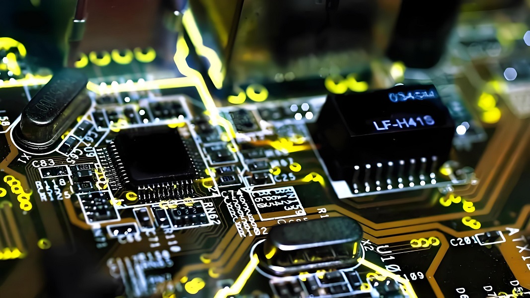
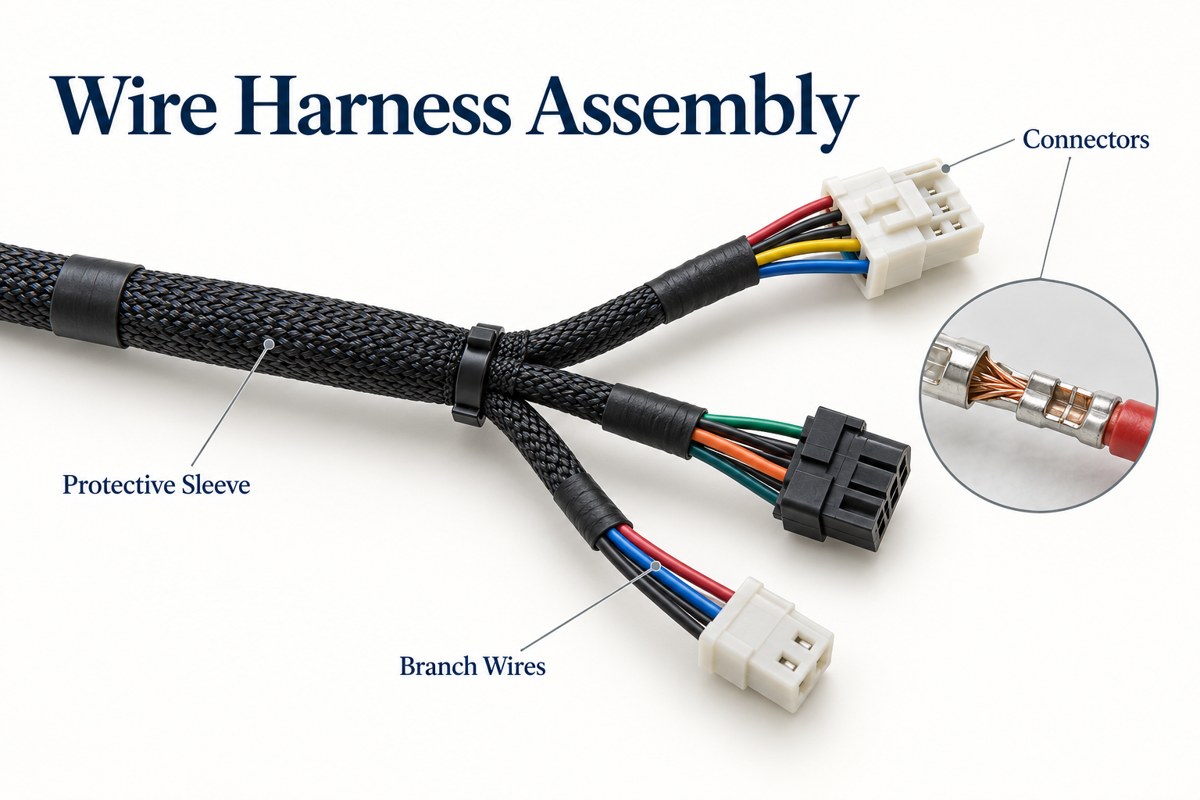
A wire harness assembly is a set of wires, terminals, connectors, and protective materials arranged to carry power or signals between parts of a product. Building it involves cutting and stripping wire, forming terminations, routing branches, and checking the completed connections. The finished harness must match both the electrical pinout and the physical installation.
At EBest Circuit, we provide custom harnesses alongside PCB fabrication, component sourcing, and PCB assembly. This lets us address the connection between a board, its wiring, and the enclosure as part of the same project.
Key Takeaways
- Wire harness assembly turns individual conductors and connectors into a repeatable electrical interconnection with defined branch lengths and pin assignments.
- An assembler prepares wires, forms terminations, inserts contacts, routes the bundle, and checks it against the drawing and test requirements.
- The assembly sequence runs from material verification and wire preparation through termination, routing, protection, and final testing.
- Wire gauge alone does not establish terminal compatibility. Insulation diameter, conductor construction, contact part number, and tooling also matter.
- A form board controls physical routing; it does not prove that connector cavities are wired correctly.
- Continuity testing does not replace crimp inspection or pull testing. Electrical and mechanical checks reveal different defects.
- PCB integration needs matching connector orientation, accessible latches, and strain relief that keeps cable loads off solder joints.
What Is Inside a Wire Harness Assembly?
A harness contains insulated wires, electrical terminations, and the hardware needed to hold and protect their route. Some are simple two-ended leads; others divide into several branches connecting sensors, controls, and power inputs.
| Part | Function |
| Insulated conductors | Carry current or signals between connection points |
| Terminals and contacts | Join conductors to mating contacts or fastening points |
| Connector housings | Position contacts, provide keying, and retain the connection |
| Sleeves, tape, or tubing | Bundle wires and provide specified mechanical protection |
| Clamps and strain relief | Support the route and reduce loads at terminations |
| Identification labels | Identify circuits, branches, or assembly revisions |
A wiring diagram defines which points connect. A harness drawing adds physical details such as branch locations, finished lengths, connector views, and label positions. Production needs both kinds of information.
How Does a Wire Harness Differ from a Cable Assembly?
A wire harness typically organizes multiple conductors into a routed bundle, while a cable assembly often uses a common jacket around its conductors. The terms overlap, so the actual construction matters more than the name.
A branching harness may connect several points inside an enclosure. A jacketed USB or coaxial cable more often provides a defined connection between two interfaces. Neither name alone guarantees shielding, water resistance, or suitability for repeated flexing; those properties come from the materials and construction.
Which Custom Harness Types Can We Supply?
Our custom wire harness range includes connector harnesses, terminal harnesses, IDC cables, USB/DC cables, and coaxial cables. We also support temperature-sensor wires and harness fuse-holder configurations.
- Connector and terminal harnesses: connections between boards, switches, power inputs, and other assemblies.
- Flat and IDC cables: organized multi-conductor connections using the specified connector and cable combination.
- USB/DC and coaxial cables: interface-specific assemblies with defined connector and cable requirements.
- Hook-up wire options: PVC, PE, TPU, and LSZH materials within the agreed wire specification.
For a custom wire harness assembly, we review the actual connector and wire combination rather than treating every cable in one category as interchangeable. A sensor lead, a DC power lead, and a data cable need different selection and verification criteria.
How Should Wires and Terminals Be Selected?
Select the wire and terminal as a matched combination, using the terminal manufacturer’s conductor-size and insulation-diameter limits. Then check that the combination meets the circuit’s electrical and environmental requirements.
At EBest Circuit, our wire harness assembly capabilities include the following wire and insulation ranges. We match each wire to the specified terminal and tooling before production.
| Parameter | Our Supported Range |
| Copper wire size | 20–17 AWG |
| Conductor cross-sectional area | 0.5–1.0 mm² |
| Wire insulation outside diameter | 1.2–2.1 mm |
For assemblies using TE Connectivity contact 1-929989-0, these ranges must be checked against the selected wire and contact specification. AWG and metric wire sizes are separate selection designations, not exact one-to-one conversions. A wire with the correct conductor size can still have insulation that is too large for the contact or seal.
- Electrical load: account for current, conductor resistance, voltage drop, and temperature rise in the installed bundle.
- Environment: specify temperature exposure, abrasion, chemicals, moisture, and any flame or smoke requirements.
- Termination: match conductor size and construction, insulation diameter, contact plating, and approved tooling.
- Motion: distinguish fixed wiring from cables designed for repeated bending.
Connector pitch is only one dimension. Mating family, keying, contact gender, cavity numbering, and latch geometry also determine whether two connectors work together.
Wire Harness Assembly Process
The wire harness assembly process converts an approved drawing and bill of materials into a terminated, routed, protected, and tested assembly.
- Verify materials: check wire markings, connector and terminal part numbers, seals, sleeves, and drawing revision.
- Cut and identify: prepare wires to the specified cut lengths and apply identification where required.
- Strip insulation: expose the conductor to the termination specification without damaging strands.
- Form terminations: crimp, use IDC, or solder according to the selected connection method. Install seals or sleeves first when they cannot pass over the finished terminal.
- Populate housings: insert each contact into its assigned cavity and verify retention and any secondary lock.
- Route the bundle: position branches, apply protection, and secure the harness without crushing insulation.
- Inspect and test: check dimensions, workmanship, pin mapping, and the agreed electrical requirements.
Cut length and finished assembly length are not always identical. The drawing needs a clear measurement datum, such as a connector mating face or a defined termination point.
What Does a Wire Harness Assembly Board Do?
A wire harness assembly board holds the bundle in its intended shape while operators route wires and position branches. Pegs and connector holders make the physical arrangement repeatable.
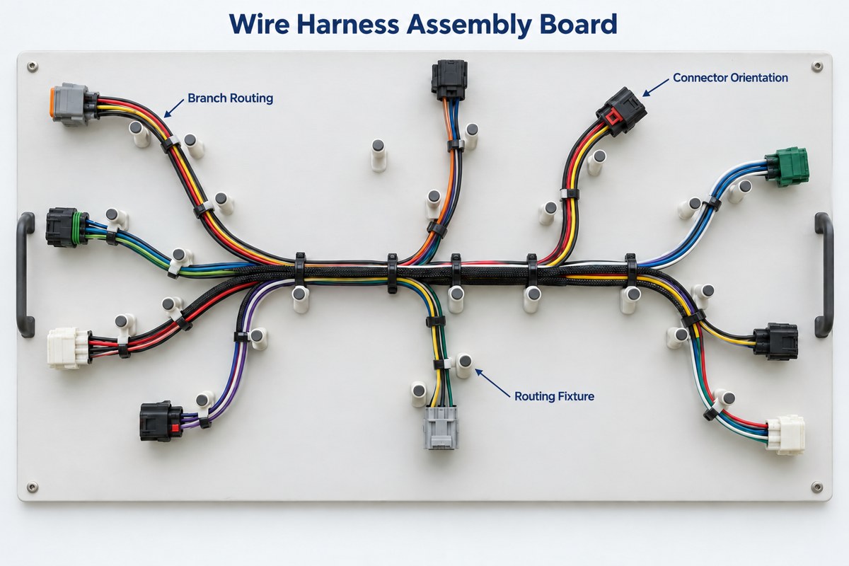
The board represents the harness layout; it is not a printed circuit board. Its controlled drawing should identify connector orientation, branch points, and dimensional references. A flat fixture also cannot fully reproduce a three-dimensional enclosure, so a first assembly should be checked in its intended installation.
Electrical testing remains separate. A harness can fit the fixture perfectly and still have two contacts inserted into the wrong cavities.
Which Wire Harness Assembly Tools Are Needed?
Wire harness assembly tools include wire cutters, stripping tools, termination tools, insertion or extraction tools, and inspection equipment. The terminal system determines the crimper and die, not just the wire gauge.
| Operation | Typical tooling |
| Wire preparation | Length-controlled cutter and suitable insulation stripper |
| Crimp termination | Specified hand tool, applicator, or crimp press tooling |
| IDC termination | Connector-specific press tooling and support fixture |
| Contact placement or removal | Compatible insertion and extraction tools |
| Crimp verification | Magnification, appropriate crimp micrometer, and pull-test equipment |
| Electrical verification | Harness tester with mating adapters and a validated test program |
Molex identifies strip length, crimp height, and pull-force requirements in its Application Tooling Specifications. These documents are tied to particular tools and terminals. A similar-looking die is not evidence that a substitute tool produces an acceptable termination.
How Is Crimp Quality Checked?
Crimp quality is checked through workmanship inspection, specified dimensions, and mechanical testing—not appearance alone.
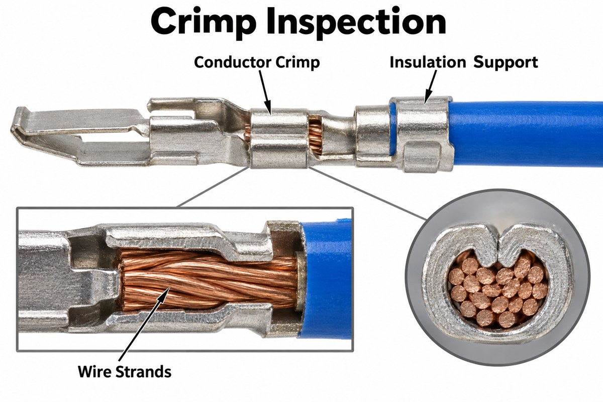
Inspect conductor placement, strand damage, insulation position, and terminal deformation. The conductor crimp and insulation support perform different jobs. Insulation trapped inside the conductor crimp can prevent the intended metal-to-metal connection.
Our crimping capabilities include the following 18 AWG configuration with Molex terminal series 84590. We can meet these dimensional and pull-force requirements for this specified combination.
| Parameter | Our Supported Configuration |
| Wire size | 18 AWG |
| Terminal series | Molex 84590 |
| Reference conductor crimp height | 1.46–1.54 mm |
| Minimum pull force | 111.2 N |
| Application tooling specification | ATS-6381157HM |
For this configuration, pull testing excludes the influence of the insulation crimp. Other terminal and wire combinations use their own approved crimp-height and pull-force limits.
A destructive pull test evaluates a sample termination; it is not a test to perform on every finished connection that will be shipped. Define sampling, measurement methods, and acceptance criteria in the production plan.
Which Tests Verify a Finished Harness?
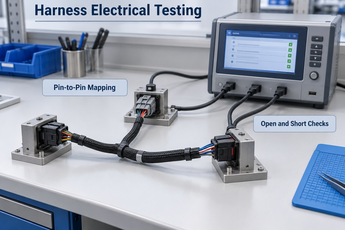
Pin-to-pin testing checks the wiring pattern and detects opens, shorts, and miswires. Additional tests address resistance or insulation performance when the product specification requires them.
| Test | What it checks |
| Continuity and pin mapping | Required connections exist at the correct connector cavities |
| Short-circuit check | Unintended connections between circuits |
| Connection resistance | The measured path remains below the specified limit |
| Insulation resistance | Isolation between designated circuits under specified DC conditions |
| Dielectric withstand | Insulation withstands the specified test voltage without breakdown |
A continuity pass does not prove adequate mechanical retention or insulation performance. Validate test fixtures and the pin map against the approved drawing; otherwise, an incorrect test program can repeatedly accept an incorrect harness.
High-voltage tests require a qualified setup and product-specific limits. Do not apply a generic hipot voltage to a harness connected to a PCB, sensor, or embedded electronic component. Such components may need isolation or a specifically designed test sequence.
What Causes Wire Harness Assembly Failures?
Common causes include damaged strands, incorrect cavity assignments, poorly retained contacts, and mechanical stress at the cable exit. Inspection is most effective before sleeving or bundling hides the termination.
- Intermittent open circuit: inspect contact seating, damaged conductors, and a loose or unsuitable crimp.
- Incorrect function: compare connector cavity numbers and drawing view orientation before assuming a PCB fault.
- Localized heating: investigate connection resistance, current loading, and the terminal-wire combination.
- Insulation wear: look for sharp enclosure edges, over-tight ties, or movement against nearby hardware.
- Terminal push-back: check contact retention and housing locks rather than pushing the connector together harder.
IPC/WHMA-A-620 provides requirements and acceptance criteria for cable and harness assemblies, including crimped, soldered, and mechanically secured interconnections. Specify the applicable revision and acceptance class for the project. Referencing the standard does not establish a manufacturer’s certification.
How Should a Harness Connect to a PCB Assembly?
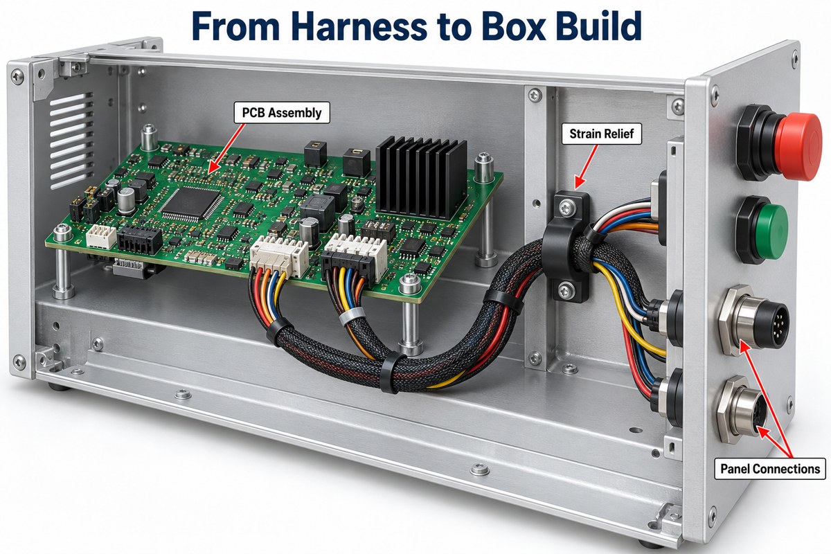
The harness must match the board connector’s pinout and mating orientation, with mechanical support that prevents cable loads from reaching solder joints.
Review the connector from the specified viewing direction. A mating-face view and a wire-entry view can reverse the apparent cavity order. During PCB assembly planning, check access to the latch and confirm that the connector can be inserted without excessive force on the board.
- Keep routing clear of sharp edges, moving parts, and hot components.
- Provide the specified bend radius and enough service slack for assembly and maintenance.
- Use clamps or strain relief where cable loads could reach contacts or soldered joints.
- Verify installed fit before freezing the branch lengths for production.
Our box build assembly service connects PCB assembly with wiring and enclosure integration. For these projects, reviewing the board, harness, and mechanical layout together helps identify mismatched interfaces before final assembly.
How Should You Compare Wire Harness Assembly Companies?
Compare wire harness assembly companies by their ability to control the exact termination, pinout, and installed fit—not simply their list of cable types.
Ask how the proposed build will be verified. Useful evidence includes the approved terminal/tool combination, a first-article dimensional check, and a test program tied to the released wiring diagram. For repeated orders, confirm how drawing revisions and material substitutions are controlled.
Price comparisons should use the same scope. Connector choice, branch count, manual routing, protective materials, tooling, and testing can change the work involved. A quote for loose harnesses is not directly comparable with one that includes installation and system testing.
FAQ About Wire Harness Assembly
Can wire colors replace circuit labels?
No. Colors help identification, but the pin map and circuit identifiers remain the production reference. Repeated colors or approved material substitutions can otherwise make two circuits easy to confuse.
Does a sealed connector make the entire harness waterproof?
No. Sealing depends on the complete construction, including the correct wire seals, cavity plugs, mating interface, and installation. A connector’s rating cannot automatically be assigned to the whole harness.
Can two wires be crimped into one terminal?
Only when that terminal and tooling are specified for the particular double-wire combination. Two wires that physically fit in a barrel do not establish an approved electrical or mechanical connection.
Is an IDC termination the same as a crimp?
No. An insulation-displacement contact reaches the conductor through its insulation using a contact slot. A conventional conductor crimp compresses the terminal around a prepared conductor. Each method requires its own compatible wire and tooling.
Can a sample harness replace a controlled drawing?
A sample can help establish routing and fit, but it does not reliably communicate hidden connections, material specifications, or acceptance limits. Document those details before using the sample as a production reference.
Need a Harness That Fits Your PCB and Enclosure?
At EBest Circuit, we support custom wire harnesses, PCB fabrication, PCB assembly, and box build integration. Send your harness drawing or pin map, connector part numbers, quantities, and installation requirements to sales@bestpcbs.com. We can review the connection requirements alongside your PCBA project and clarify the assembly and testing scope before quotation.