The key difference in TVS diode vs Zener diode applications is the job each device performs: a conventional Zener maintains a voltage during normal operation, while a TVS limits brief voltage spikes. Both use reverse breakdown, but their voltage and power ratings describe different operating conditions.
Picture two parts of the same board. A small reference circuit needs a reasonably stable voltage while current flows. An external connector needs a protection path that conducts strongly when a transient arrives. These two situations explain why similar-looking diodes can behave very differently in a circuit.
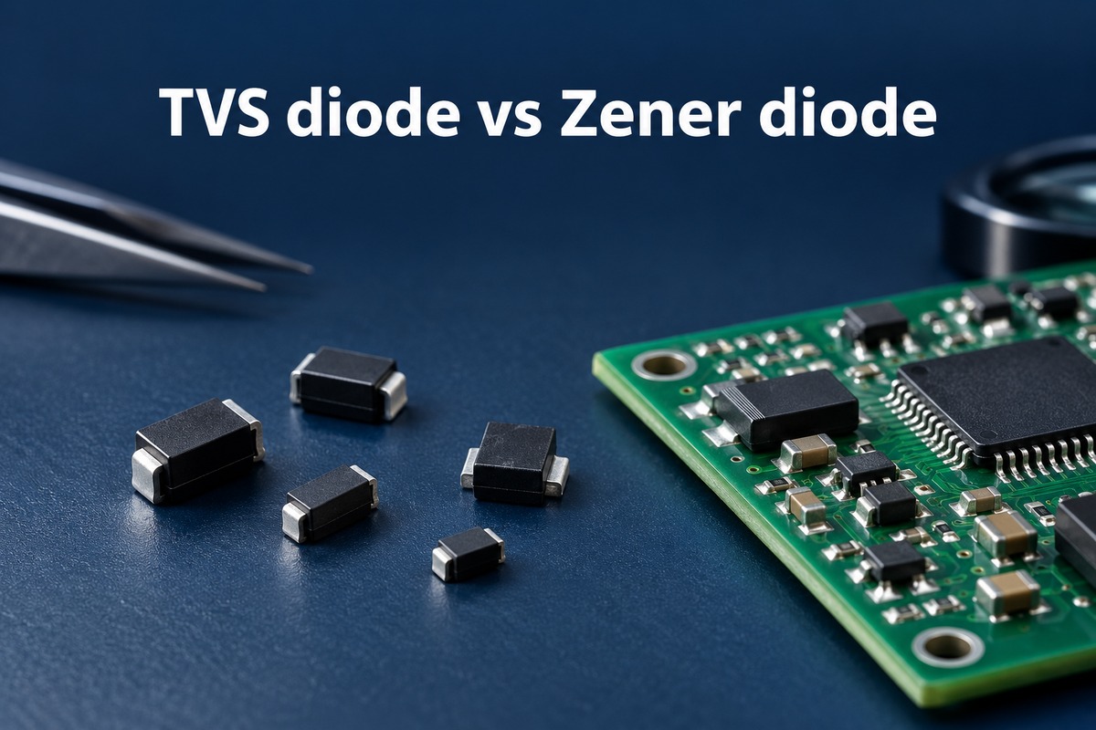
What Is the Difference Between a TVS Diode and a Zener Diode?
A Zener regulator conducts as part of normal operation. A TVS normally carries only leakage current until an overvoltage event occurs.
| Circuit behavior | Conventional Zener regulator | TVS protection circuit |
|---|---|---|
| Main purpose | Establish or regulate a voltage | Suppress a transient voltage rise |
| When substantial current flows | During normal regulation | During the transient |
| Performance that matters | Voltage stability over current and temperature | Clamping voltage at the transient current |
| Main stress | Continuous dissipation | Pulse current and heating |
A regulating Zener operates in reverse breakdown, where its voltage changes relatively little over a suitable current range. A TVS generally stays below breakdown until a spike makes it conduct and divert current through the protection path.
These are the usual roles. Some Zeners also carry protection ratings; that distinction matters when considering a replacement, rather than changing the basic comparison.
Where Are TVS Diodes and Zener Diodes Used in Circuits?
Zeners commonly serve local reference or limiting circuits; TVS devices commonly protect exposed power and signal connections. Their surrounding connections show how those roles differ.
A small voltage reference:
A resistor feeds a node shared by the load and a reverse-biased Zener. The resistor limits current, and the load and Zener divide that current between them. As load current rises, less remains for the Zener. If too little remains, the node falls out of regulation.
A DC power input:
A TVS connects across the supply and its return. It carries little current at the normal supply voltage, then diverts current during a spike. The source impedance and coordinated protection affect the pulse current it must carry.
An external signal interface:
A protection device sits near the connector, where it can divert incoming transient current. Here, low signal loading matters as well as protection. A low-capacitance interface protector can suit a fast data line that a larger power-line suppressor would load excessively.
For each application, voltage limiting and stress survival are separate questions. The next two sections explain them in that order.
How Does Zener Diode Clamping Compare with TVS Clamping?
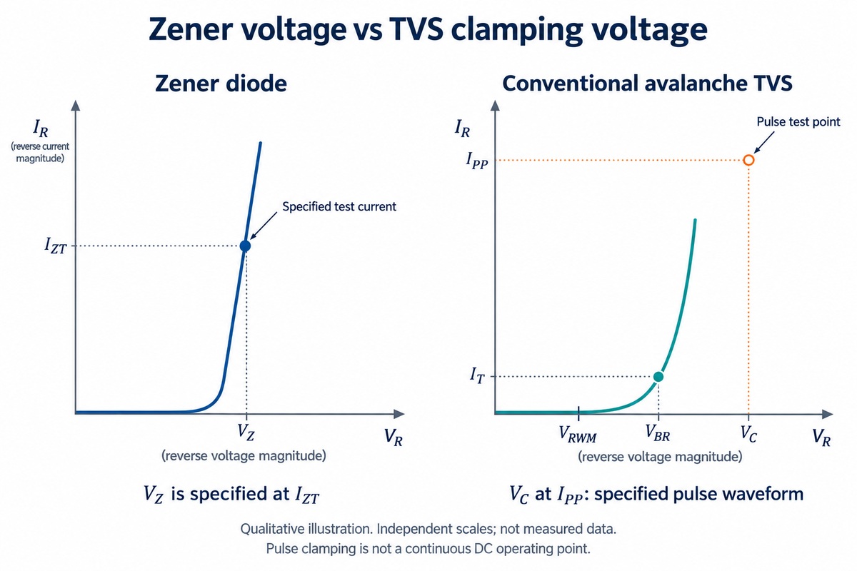
Clamping limits a voltage rise; it does not hold the voltage perfectly constant. The voltage across the diode changes with current, so the test conditions are part of the specification.
| Parameter | What it means | Circuit relevance |
|---|---|---|
| Zener voltage, VZ | Reverse voltage at a stated test current | Describes a regulation operating point |
| TVS working voltage, VRWM | Reverse standoff voltage with a specified leakage limit | Relates to normal operation before a spike |
| TVS breakdown voltage, VBR | Breakdown measured at a stated test current | Identifies the transition into stronger conduction |
| TVS clamping voltage, VC | Voltage at a stated pulse current and waveform | Describes device voltage during that transient test |
Example — working voltage versus clamping voltage:
Suppose a TVS specifies a 5 V working voltage and a 9 V clamping voltage at its rated pulse current. During that test, approximately 9 V can appear across its terminals. The 5 V working rating describes normal operation, not the voltage held during the surge. These hypothetical values illustrate the relationship, not a recommended part for a 5 V circuit.
A Zener rated 5.1 V at a small test current describes another operating point. That number alone does not tell us its voltage at a much higher transient current.
At the connector, VC at the relevant pulse current relates to the protected circuit's transient voltage tolerance. VRWM relates to the normal line-voltage range.
Why Are TVS Pulse Power and Zener Power Ratings Different?
The difference is how long the power lasts. Short pulses and continuous operation heat a diode differently.
Continuous operation in a Zener reference:
Power is approximately the Zener voltage multiplied by its current. For an illustrative operating point:
5.1 V × 10 mA = 51 mW
That heat is produced for as long as the current flows. The device's continuous rating and mounting conditions determine whether it can dissipate it adequately.
A transient at a TVS-protected input:
Instantaneous power is also voltage multiplied by current, but heating depends on the entire pulse. A broad pulse deposits more energy than a narrow pulse with the same peak and a comparable shape.
Three conditions explain why pulse ratings come with qualifications:
- Pulse duration and shape: These determine how power changes over time.
- Repetition: Closely spaced pulses can cause heat to accumulate.
- Starting temperature: A hot device has less thermal margin available.
The large peak-wattage figure on a TVS listing is therefore a pulse capability, not a continuous dissipation allowance.
How Do Unidirectional and Bidirectional TVS Diodes Compare with Zener Diodes?
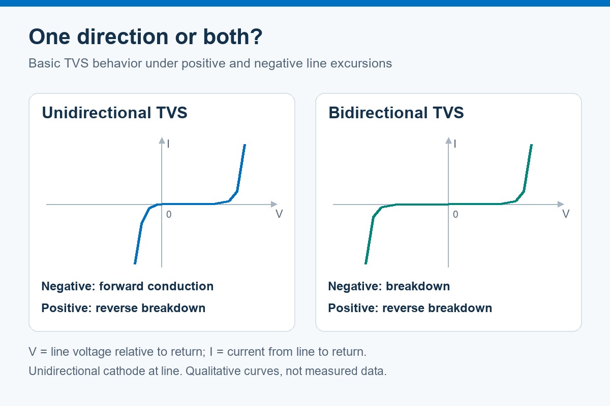
A unidirectional device limits the two polarities differently; a bidirectional TVS provides a specified limiting characteristic in both directions.
For the comparison below, a unidirectional device has its cathode connected to the line and its anode to return.
| Applied excursion | Basic unidirectional TVS or conventional Zener | Bidirectional TVS |
|---|---|---|
| Positive voltage beyond the relevant threshold | Reverse-breakdown conduction | Conduction according to its positive limiting characteristic |
| Negative voltage beyond the relevant threshold | Forward conduction | Conduction according to its negative limiting characteristic |
| Normal signal swings below return | May clip the negative signal through forward conduction | Can accommodate both polarities within its working range |
This explains why a unidirectional TVS can respond to both positive and negative transients without having the same limiting voltage in both directions.
For a signal that normally swings above and below its reference, a suitable bidirectional protector preserves that normal range. Opposing Zener junctions help explain the basic concept, but two arbitrary Zeners do not reproduce a TVS device's pulse capability or capacitance. Some protection devices also use more elaborate internal networks.
How Do TVS and Zener Diode Capacitance and Leakage Affect Circuit Operation?
A protection diode can affect the circuit even before it clamps. Capacitance influences changing signals; leakage affects small DC currents.
Capacitance on signal lines:
The signal driver must charge and discharge the added capacitance. Together with the line impedance, this can slow edges and distort the waveform.
- Most relevant to fast interfaces and other bandwidth-sensitive signals.
- Can make a power-line suppressor unsuitable for a data connection.
- Is specifically reduced in low-capacitance protection devices.
Leakage in sensitive circuits:
Leakage creates a small current path through the diode during normal operation. At a high-impedance sensor input, that current can produce a voltage drop across the source resistance and shift the reading. It also contributes to standby consumption in battery-powered equipment.
The useful comparison is between individual parts under relevant conditions. Capacitance specifications include bias and frequency; leakage specifications include voltage and temperature. Neither diode family is automatically better in every circuit.
Can a Zener Diode Replace a TVS Diode?
Sometimes, provided it preserves both the protection function and normal circuit operation. A matching voltage marking is only one piece of that comparison.
Replacing a TVS with a Zener:
At a current-limited internal node, a suitable Zener may provide sufficient voltage limiting. At an exposed connector, the replacement also needs appropriate clamping behavior and transient-current capability. Protection-rated Zeners may satisfy these conditions; an ordinary regulation Zener should not be assumed to do so.
Replacing a regulating Zener with a TVS:
The reference circuit requires continuous operation at its intended bias current. Voltage tolerance, temperature behavior and continuous dissipation become central. A high TVS surge rating does not establish accurate regulation at that current.
On a signal line:
The replacement must also preserve the signal's polarity range and loading. A device that survives the surge but clips normal signals or shifts a sensitive input has changed the circuit's behavior.
FAQs About TVS Diodes and Zener Diodes
Are TVS diodes always faster than Zener diodes?
No universal speed ratio applies. Construction, packaging and test conditions affect the result. The voltage that reaches the protected circuit during the event is more useful than an isolated response-time claim.
Can a TVS diode handle a sustained supply fault?
A pulse rating does not establish sustained-fault capability. Continued conduction can overheat the device. Current limiting or disconnection may be needed to end the fault.
Can the package or schematic symbol identify a TVS diode?
Not reliably. TVS and Zener devices can share packages and similar symbols. The part number and data sheet establish their type, polarity and ratings.
Can a multimeter confirm that a TVS diode is healthy?
It can help reveal a short, but cannot verify surge performance. A bidirectional TVS may read open in both directions at the meter's test voltage. Parallel circuit paths can also affect an in-circuit reading.
Why can a suitable TVS still leave an IC exposed to excessive voltage?
The IC sees the voltage at its pins. Inductance in a long discharge path can add voltage during a fast current rise. Placement near the entry point and a short return path help the protection circuit perform as intended.
The TVS diode vs Zener diode distinction carries through to the assembled board, where component identity, orientation and layout matter alongside the electrical design. EBest Circuit combines component sourcing, PCB fabrication and assembly for customer-approved designs. For support with your next prototype or production PCBA build, contact sales@bestpcbs.com.