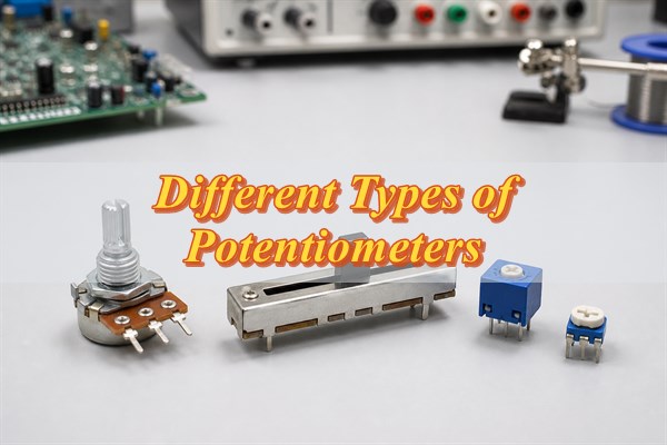
The different types of potentiometers most designers compare are rotary, slide, trimmer, and digital potentiometers. Rotary and slide types are routine human controls, trimmers are compact calibration controls, and digital potentiometers replace mechanical movement with electronic adjustment. The right choice also depends on resistance, taper, turn count, element construction, power, mounting, and environmental ratings.
These names are easy to mix because they do not all describe the same feature. A part can be rotary, logarithmic, dual-gang, conductive-plastic, and panel-mounted at the same time. This guide keeps the type map compact, explains the differences that change a real selection, and ends with a practical method for choosing an exact part.
What Are the Different Types of Potentiometers?
Use this table as a classification map, not as a list of mutually exclusive products. Each group answers one engineering question: how the control moves, how finely it must be adjusted, or whether the setting is mechanical or electronic. Compare options only within the same classification dimension.
| Classification Dimension | Potentiometer Type | Preferred Application | Critical Selection Criteria |
|---|---|---|---|
| Interface motion | Rotary potentiometer | Compact knobs, dials, and panel set-point controls | Rotation angle, shaft and bushing geometry, operating torque, and taper |
| Interface motion | Slide potentiometer | Visible linear position control, including faders and multi-channel interfaces | Travel length, lever geometry, mounting support, and contamination protection |
| Calibration resolution | Single-turn trimmer | Fast, compact calibration when fine mechanical resolution is unnecessary | Tool access, setting stability, adjustment range, and end-stop protection |
| Calibration resolution | Multi-turn trimmer | Fine calibration where a narrow target must be approached gradually | Turn count, adjustment time, end-stop torque, and mechanical life |
| Control architecture | Mechanical potentiometer | Direct hand or tool adjustment without firmware control | Operating life, contact-resistance variation, sealing, and environmental rating |
| Control architecture | Digital potentiometer | Remote, automatic, or repeatable adjustment controlled by a processor | Terminal voltage limits, wiper resistance, resolution, interface, and memory behavior |
A finished component can combine one option from more than one group. For example, a multi-turn trimmer is also mechanical, while a rotary potentiometer may use a linear or audio taper and a carbon, cermet, or conductive-plastic element. Use the table to select the control format first, then apply the electrical specifications in the sections below. Do not compare rotary and digital as though they were mutually exclusive alternatives.
How Do Rotary, Slide, and Trimmer Potentiometers Differ?
Rotary and slide potentiometers are selected by the required user motion, while trimmers are selected for occasional calibration. None is inherently more accurate or reliable; the exact series, construction, and ratings determine performance.
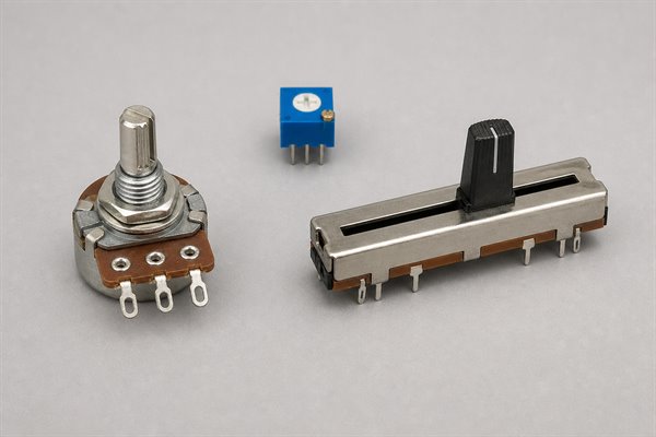
- Rotary potentiometers: A shaft turns the wiper along a resistive track. They fit compact knobs, dials, audio controls, set-point controls, and many panel interfaces. Check the rotation angle, shaft profile and length, bushing, torque, end stops, panel thickness, and clockwise electrical direction.
- Slide potentiometers: A lever moves the wiper along a straight track. The lever position is immediately visible, which suits mixers, lighting controls, and other interfaces where users compare several settings. Check travel length, lever style, mounting support, dust protection, and clearance through the full stroke.
- Single-turn trimmers: A tool adjusts the setting over roughly one turn or less. They suit compact, cost-sensitive calibration where the target does not require extremely fine mechanical adjustment. Verify tool access and whether the setting can move during handling, vibration, or cleaning.
- Multi-turn trimmers: A screw mechanism spreads the electrical range over several turns. This makes a narrow target easier to approach, but adjustment takes longer and excessive end-stop torque can damage the mechanism. Use them when calibration resolution justifies the extra space, cost, and production time.
A trimmer is still a potentiometer; the term describes its adjustment role. Likewise, a rotary part can be single-turn or multi-turn, and a slide part can use different electrical tapers. Use the mechanical drawing and the complete order code to verify the actual combination.
Which Electrical Differences Matter When Choosing a Potentiometer?
After choosing the physical format, six electrical differences usually decide whether the part will work in the circuit. Compare these values in the exact candidate datasheet rather than relying on the type name or body marking.
- Total resistance: Choose the nominal end-to-end resistance from the source impedance, load, current, noise, and power requirements. A 10 kΩ part is not interchangeable with every other 10 kΩ part because the surrounding circuit changes the usable wiper output.
- Electrical taper: A linear taper changes resistance ratio approximately in proportion to travel. A logarithmic or audio taper compresses change over part of the travel to suit perceptual controls such as audio level. Reverse-log and custom curves serve more specialized control laws. Manufacturer letter codes are not universal, so verify the curve shown for the exact order number.
- Power and wiper current: Check total element power, derating with temperature, and the worst-case current through the wiper. In a rheostat connection, the active resistance becomes smaller near one end, so current and local heating can become the limiting conditions.
- Element construction: Carbon is common in economical general-purpose controls. Cermet is widely used in stable compact trimmers. Conductive plastic can support smooth operation and long mechanical life in suitable controls. Wirewound designs can handle higher power but introduce step resolution and inductance. Treat these as selection tendencies, not guaranteed performance; compare the finished component ratings.
- Tolerance, linearity, and tracking: Total-resistance tolerance does not describe the accuracy of the wiper ratio. For sensing or dual-channel control, check independent linearity, contact-resistance variation, channel tracking, and performance at the positions that matter to the circuit.
- Life and environment: Rotational or sliding life, temperature coefficient, humidity, sealing, vibration, and contamination resistance can matter more than nominal resistance. Match the rating conditions to the product environment and expected number of adjustments.
The Bourns Potentiometer Handbook explains the relationships among element construction, taper, loading, power, and adjustment behavior. Use that guidance to compare options, then verify every release-critical value in the exact candidate datasheet.
How Do Digital and Mechanical Potentiometers Differ?
A mechanical potentiometer moves a physical wiper, while a digital potentiometer uses electronic switches to select resistance steps. Choose the mechanical type for direct hand or tool adjustment. Choose the digital type when a controller needs repeatable, remote, or automatic adjustment and the analog signal stays within the IC’s limits.
A digital potentiometer uses electronically controlled switches and a resistor network. It can provide fixed adjustment steps, a compact footprint, and software-controlled presets without a moving contact. Common uses include gain trim, threshold adjustment, calibration, and digitally managed analog settings.
Choose it only after checking these boundaries:
- Terminal voltage range: The A, B, and W terminals normally have device-specific limits, often related to the supply rails. Check normal operation, startup, shutdown, and fault states.
- Wiper resistance and current: Internal switch resistance affects low codes and low nominal values, while terminal current is limited. Calculate the error and stress at the worst position.
- Resolution and accuracy: The number of steps does not establish end-to-end tolerance, linearity, or temperature drift. Confirm the output range and error at the codes the application will use.
- Bandwidth and capacitance: The internal network can change AC behavior in filters, amplifiers, and feedback paths. Verify performance at the real signal frequency.
- Interface and stored state: SPI, I2C, up/down control, volatile or nonvolatile memory, write endurance, and power-up code affect both hardware and firmware behavior.
Analog Devices AN-1121 describes the architectural differences between mechanical and digital potentiometers and explains why terminal range, wiper behavior, and control method must be checked for the selected IC.
How Do You Choose the Right Potentiometer?
Choose the right potentiometer by fixing the circuit function first, then the control format, electrical behavior, ratings, package, and validation method. This seven-check sequence should end with an exact manufacturer part number or a bounded approved-vendor list. Skipping the loading, power, or mechanical checks risks approving a part that has the right nominal resistance but fails in the actual circuit or enclosure.
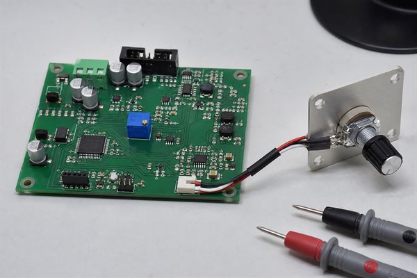
- State the adjustment job. Record whether the part sets a voltage ratio, gain, threshold, time constant, user level, position input, or calibration value. Record the required direction of change and how often the setting will move.
- Choose the control type. Use rotary or slide for routine user input, a trimmer for occasional calibration, or a digital pot for controller-driven adjustment. The observable output is one justified control architecture and physical format.
- Set resistance and taper. Calculate nominal resistance from the source and load, then choose linear, audio/logarithmic, reverse-log, or a specified custom curve from the required output-versus-travel relationship.
- Check worst-case electrical ratings. Verify terminal voltage, wiper current, element power, temperature derating, tolerance, linearity, contact-resistance variation, bandwidth, and channel tracking where applicable.
- Match adjustment precision and construction. Decide whether single-turn or multi-turn motion is needed, then compare element constructions using the candidate series’ actual stability, noise, life, temperature, and power data.
- Close the mechanical and environmental fit. Confirm footprint, pin order, shaft or lever, orientation, panel thickness, mounting support, tool access, sealing, cleaning restrictions, vibration, and expected operating cycles.
- Set a simple acceptance check. Measure end-to-end resistance, output direction, useful travel, and the loaded output at important positions. For digital parts, also verify communication, power-up state, allowed code range, and recovery after reset.
Do not release a BOM entry such as "10 kΩ pot" without the remaining qualifiers. At minimum, the approved description should identify type, taper, tolerance, power, package, mounting, actuator or adjustment style, environmental option, and any tracking or life requirement that controls the design.
FAQs About Different Types of Potentiometers
Q1: What are the four main types of potentiometers?
A1: Rotary, slide, trimmer, and digital is a useful practical list. However, the labels use different axes: rotary and slide describe motion, trimmer describes adjustment role, and digital describes control architecture.
Q2: What is the difference between a potentiometer and a rheostat?
A2: A potentiometer normally uses three terminals as a voltage divider. A rheostat connection uses the wiper and one end terminal as a two-terminal variable resistance. A three-terminal potentiometer can often be wired either way within its ratings.
Q3: Why does a potentiometer have three terminals?
A3: Two terminals connect to the ends of the resistive element, and the third connects to the movable wiper. Applying voltage across the two ends lets the wiper produce an adjustable fraction of that voltage.
Q4: Is a trimmer the same as a potentiometer?
A4: Yes, a trimmer is a potentiometer designed mainly for calibration or occasional service adjustment. It is usually tool-operated and board-mounted rather than intended for frequent user control.
Q5: Is a multi-turn potentiometer more accurate?
A5: Multi-turn motion improves adjustment resolution, not every accuracy specification. Resistance tolerance, linearity, temperature coefficient, contact noise, and stability must still be checked separately.
Q6: Are A and B potentiometers linear or logarithmic?
A6: Do not treat A and B as universal taper codes. The meaning can vary by manufacturer or family. Decode the complete part number and check the current curve drawing before substitution.
Q7: Can a linear potentiometer control audio volume?
A7: It can change level, but the control may feel uneven to the listener. A suitable logarithmic or audio taper often spreads perceived loudness adjustment more usefully across the travel. Confirm the source and load circuit as well as the curve.
Q8: Can a digital potentiometer pass a signal above its supply voltage?
A8: Many digital potentiometers cannot. A, B, and W terminal limits are device-specific and are often tied to the supply rails. Check all operating and fault states in the selected datasheet.
Q9: How can you identify a potentiometer’s resistance value?
A9: Decode the body marking with the manufacturer’s ordering information, then measure between the two end terminals. Resistance alone does not identify taper, tolerance, power, pin order, or environmental rating.
Q10: What causes a potentiometer to become noisy or intermittent?
A10: Common causes include wiper or element wear, contamination, mechanical damage, cracked solder joints, excessive wiper current, or noise in the surrounding circuit. Sweep the control while monitoring resistance or output to determine whether the fault follows wiper position.
Conclusion
Start with rotary, slide, trimmer, or digital as the control choice, then qualify that choice with the electrical taper, resistance, ratings, construction, and package. This keeps the different types of potentiometers easy to understand without treating every feature as a separate category. The final decision should be an exact part whose datasheet limits and mechanical drawing match the circuit and product.
If a potentiometer is part of a PCB or PCBA project, send the BOM or candidate part number, required resistance and taper, adjustment function, quantity, enclosure constraints, operating environment, and acceptance requirements to sales@bestpcbs.com for component and assembly review.