Thick film resistor TCR describes how much a resistor’s resistance changes with temperature, usually expressed in ppm/°C. Understanding common TCR ratings helps you estimate temperature drift and its effect on circuit accuracy. Practical examples show when standard thick film resistors meet your needs and when a lower-TCR option is worth choosing.
At EBest Circuit, we’ve supported PCB and PCBA projects for customers in the United States, Germany, and Israel, including established medical device brands. Our dedicated engineering and quality management teams help customers turn design requirements into production-ready boards, with practical support when manufacturing challenges arise.
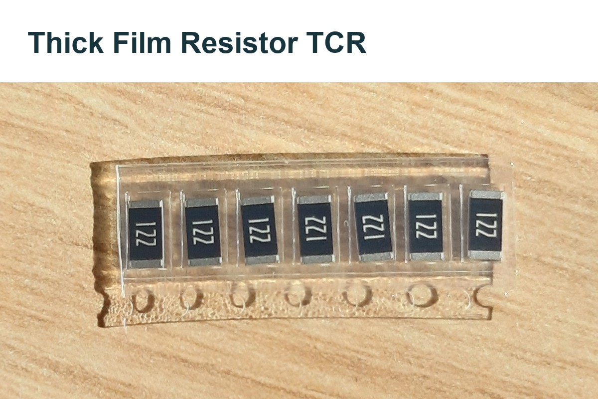
What Does Thick Film Resistor TCR Mean?
The temperature coefficient of resistance (TCR) describes the relative change in resistance per degree of temperature change. A value of 100 ppm/°C corresponds to approximately 0.01% per °C.
A positive TCR means resistance increases as temperature rises; a negative TCR means it decreases. A datasheet rating of ±100 ppm/°C specifies a limit under the stated test conditions. It does not mean that every resistor has an actual coefficient of +100 or −100 ppm/°C.
TCR and resistance tolerance describe different sources of error. Tolerance specifies the initial resistance range at a reference condition, while TCR describes temperature-related change. A resistor with tight initial tolerance can still drift noticeably during operation.
What TCR Values Do Thick Film Resistors Offer?
Thick film resistor TCR ratings commonly include ±100 and ±200 ppm/°C, while precision series offer options such as ±50 or ±25 ppm/°C. The available rating depends on the specific series, resistance value, package, and temperature range.
| TCR rating | Approximate resistance change over 60°C | Selection context |
|---|---|---|
| ±200 ppm/°C | ±1.20% | General-purpose circuits with a relatively wide error allowance |
| ±100 ppm/°C | ±0.60% | General-purpose designs requiring less thermal drift |
| ±50 ppm/°C | ±0.30% | Tighter temperature-stability requirements |
| ±25 ppm/°C | ±0.15% | Precision applications where this drift fits the error budget |
These figures estimate the temperature contribution alone, assuming the stated coefficient applies across the temperature interval. They exclude initial tolerance and long-term resistance change.
Check the TCR specification for the exact orderable part. A series may specify different limits for different resistance ranges, and low-resistance or very high-resistance values may have wider limits. Also check whether the datasheet specifies separate behavior above and below the reference temperature.
How Do You Calculate Resistance Change from TCR?
Multiply the reference resistance by TCR and the temperature change to estimate resistance drift. For an approximately constant coefficient:
ΔR ≈ Rref × α × ΔT × 10⁻⁶
Here, Rref is resistance at the reference temperature, α is TCR in ppm/°C, and ΔT is the resistor’s temperature change in °C. The corresponding percentage change is:
Resistance change (%) ≈ α × ΔT ÷ 10,000
For a 10 kΩ resistor warming from 25°C to 85°C, ΔT is 60°C:
| TCR magnitude used | Estimated resistance change | Change relative to 10 kΩ | Estimated resistance range* |
|---|---|---|---|
| 25 ppm/°C | ±15 Ω | ±0.15% | 9,985–10,015 Ω |
| 50 ppm/°C | ±30 Ω | ±0.30% | 9,970–10,030 Ω |
| 100 ppm/°C | ±60 Ω | ±0.60% | 9,940–10,060 Ω |
| 200 ppm/°C | ±120 Ω | ±1.20% | 9,880–10,120 Ω |
Assumes exactly 10 kΩ at 25°C and an applicable ±TCR limit. Initial tolerance, aging, and other effects are excluded.
A ±100 ppm/°C part therefore contributes approximately ±0.6% temperature-related resistance change over this interval. If its initial tolerance is ±1%, a conservative first-order estimate allows roughly ±1.6% combined deviation before other errors are included.
How Do Self-Heating and PCB Temperature Affect Resistance?
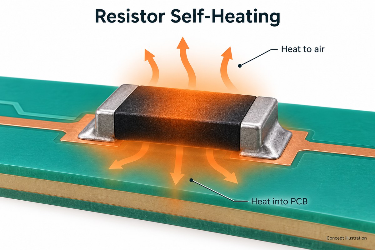
TCR calculations should use the resistor’s operating temperature, not simply the surrounding air temperature. That temperature reflects both heat from the PCB and nearby components and heat generated by the resistor itself.
Resistor power dissipation is P = I²R, or P = V²/R. The resulting temperature rise depends on the package, copper layout, mounting conditions, and airflow; it cannot be determined from power alone.
For example, suppose the local ambient temperature is 60°C, but self-heating raises the resistor to 85°C. Relative to a 25°C reference, a 100 ppm/°C coefficient gives approximately 0.6% resistance change, rather than the 0.35% estimated from ambient temperature alone.
Operating below the power rating does not guarantee negligible thermal drift. For precision circuits, evaluate temperature under the intended load and PCB conditions, while observing the manufacturer’s power-derating limits.
How Does TCR Affect Voltage Dividers and Analog Circuits?
A voltage divider’s temperature stability depends primarily on how its two resistors change relative to each other. Equal fractional changes cancel in the divider ratio, while unequal changes shift the output.
For an unloaded divider with upper resistor R1 and lower resistor R2:
Vout = Vin × R2 ÷ (R1 + R2)
The following example assumes initially equal resistors, a stable input voltage, and the same 60°C temperature rise for both resistors. The listed TCRs represent their actual coefficients in this simplified model.
| R1 actual TCR | R2 actual TCR | R1 change | R2 change | Output change relative to its initial value |
|---|---|---|---|---|
| +100 ppm/°C | +100 ppm/°C | +0.6% | +0.6% | 0% |
| +100 ppm/°C | −100 ppm/°C | +0.6% | −0.6% | −0.6% |
| −100 ppm/°C | +100 ppm/°C | −0.6% | +0.6% | +0.6% |
Two resistors carrying the same ±100 ppm/°C rating are not guaranteed to track each other. Their actual coefficients may differ. For precision dividers and amplifier gain networks, a specified TCR tracking or ratio-temperature-coefficient limit is more useful than matching individual TCR ratings alone.
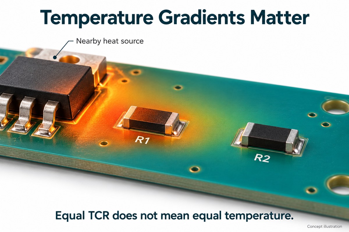
Temperature gradients also matter. Even resistors with identical coefficients change by different amounts if one runs hotter. Keep ratio-critical resistors close together and away from uneven heat sources; consider a resistor network with specified tracking when the accuracy requirement justifies it.
When Is a Lower-TCR Resistor Worth Using?
Use a lower-TCR resistor when predicted thermal drift exceeds the resistance-related error allowed by the circuit. This is especially relevant to precision sensing, reference scaling, amplifier gain setting, and measurement equipment operating across a wide temperature range.
For example, if a resistor is allowed only 0.2% temperature-related change over an 80°C interval:
Maximum TCR magnitude ≈ 0.2 × 10,000 ÷ 80 = 25 ppm/°C
A ±25 ppm/°C resistor uses the entire thermal-drift allowance in this estimate. Select a tighter rating if margin is required. If 0.2% is the total accuracy budget, initial tolerance and other errors must receive part of that budget as well.
| Circuit requirement | Selection approach | Main consideration |
|---|---|---|
| Pull-ups, logic biasing, and other tolerant functions | Standard thick film is often sufficient | Confirm that resistance variation remains within functional limits |
| Moderate precision with tighter thermal limits | Evaluate precision thick film | Check the exact resistance value and available TCR grade |
| Low drift combined with low excess noise | Compare suitable thin film series | Check TCR, noise, stability, and operating limits |
| Stable divider ratio or amplifier gain | Evaluate a matched resistor network | Prioritize specified tracking and similar operating temperatures |
| Significant pulse or surge exposure | Choose a suitably rated series | Low TCR alone does not establish pulse capability |
Precision thick film and thin film should be compared at the part level. Thin film often offers lower TCR and lower excess noise, while precision thick film may meet the accuracy requirement without changing resistor technology. For ratio-based circuits, improving tracking can provide more value than reducing each resistor’s individual TCR.
FAQs About Thick Film Resistor TCR
Can a room-temperature resistance measurement verify TCR?
No. It checks resistance at one temperature. Verifying TCR requires measurements at controlled temperatures, with sufficient settling time and low enough measurement power to avoid significant self-heating.
Are ppm/°C and ppm/K equivalent for resistor TCR?
Yes. A temperature change of 1°C equals a change of 1 K, so the numerical coefficient is the same.
Does a zero-ohm jumper have a useful TCR specification?
Usually, maximum resistance, current rating, and temperature rise are more useful selection criteria. Follow the jumper’s datasheet rather than treating its nominal zero-ohm value as an ordinary resistor in a TCR calculation.
Does laser trimming guarantee low TCR?
No. Laser trimming adjusts resistance toward a target value. It does not, by itself, guarantee a particular temperature coefficient.
Is a negative TCR a sign of a defective resistor?
No. A negative coefficient is acceptable when it falls within the manufacturer’s specification. Whether it suits the application depends on the circuit’s temperature behavior.
Can two resistors with the same resistance and TCR rating be substituted directly?
Not on those two specifications alone. Also compare tolerance, package, power derating, working voltage, pulse capability, and applicable reliability requirements.
For PCB fabrication and PCBA support for your thick film resistor TCR requirements, contact EBest Circuit at sales@bestpcbs.com with your project requirements. Our engineering and quality teams can help coordinate manufacturing requirements from prototype through production.