A soil moisture monitoring system turns measurements from buried probes into information that helps growers understand when soil is drying and how it responds to irrigation. Reliable readings depend on more than the sensor itself. The electronics must capture a stable signal, manage power, and transfer data without allowing moisture, electrical noise, or communication faults to distort the result.
At EBest Circuit, we bring PCB fabrication, component sourcing, and in-house assembly together for custom monitoring electronics. Engineering and assembly reviews help align sensor interfaces, component packages, and board construction before production, reducing avoidable handoffs between suppliers. To discuss a sensor node, data logger, or irrigation control board, visit Contact Us and complete the form at the bottom of the page.
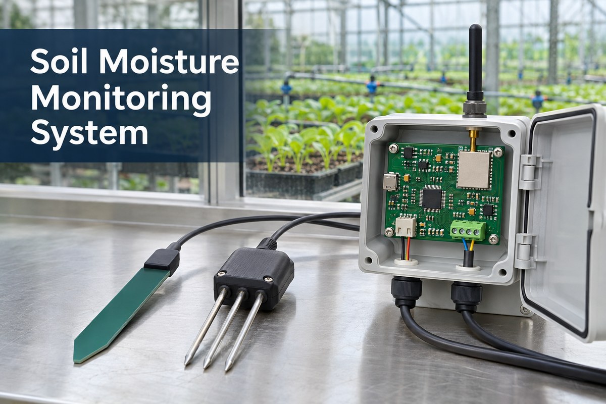
What Is a Soil Moisture Monitoring System?
A soil moisture monitoring system combines soil probes, measurement electronics, power, and a way to view or record readings. It may serve a single greenhouse bed or connect multiple locations across a farm.
Its main elements have different jobs.
- Soil probes respond to changes in soil water conditions. Depending on the technology, they indicate water content or water tension.
- Measurement and control electronics supply the probes, read their outputs, apply calibration, and associate readings with a location and time.
- Power circuits regulate battery, external DC, or solar-derived power and support sleep and wake cycles.
- Data interfaces send measurements to a local display, logger, gateway, or remote application.
Volumetric water content (VWC) and soil water tension describe different properties. VWC is the volume of water divided by the total bulk soil volume. For example, 0.25 m³/m³ equals 25% VWC. Water tension, commonly expressed in kPa, describes how tightly water is held by the soil. A percentage and a pressure reading cannot be exchanged without an appropriate soil water retention relationship.
Monitoring also differs from automatic irrigation. Opening a valve requires control logic and a suitable output stage in addition to the measurement system.
How Does a Soil Moisture Monitoring System Work?
The system follows a measurement chain from the soil to a usable reading.
1. The probe produces an electrical response
A capacitive probe responds to the dielectric properties of the surrounding material. A simple resistive probe responds to electrical conduction between exposed electrodes. The sensing circuit converts that response into an analog voltage or digital value.
2. The acquisition circuit captures the signal
An analog probe connects to an analog-to-digital converter (ADC), either inside the microcontroller or on a separate IC. Filtering, reference stability, and grounding affect how consistently the voltage is measured. A digital probe performs more of this processing internally and communicates through its specified interface.
For an illustrative 12-bit ADC with a 3.3 V full-scale range, there are 4,096 quantization levels. The ideal voltage step is approximately 3.3 V ÷ 4,096 = 0.806 mV. This is electrical resolution, not soil moisture accuracy; probe variation, calibration, noise, and reference error still contribute to the final result.
3. Calibration gives the reading meaning
Firmware converts the raw value using a calibration relationship. Mapping an air reading to 0% and a water reading to 100% creates a relative scale; it does not, by itself, establish an accurate VWC measurement in soil. Soil composition, packing, and contact with the probe affect interpretation.
4. The controller records or transmits the result
Sampling and transmission need not occur at the same interval. In an example configuration, sampling every 5 minutes produces 288 readings per day. Sending one batch every 30 minutes produces 48 scheduled uploads, each containing six readings. The dashboard updates less frequently than the sensor samples, while preserving the measurement history if the firmware stores each reading.
Capacitive vs. Resistive Soil Moisture Sensors
Capacitive sensors can isolate their sensing electrodes from direct soil contact, while basic resistive sensors need a conductive path through the soil. That difference affects corrosion exposure, calibration, and the surrounding PCB construction.
The following comparison uses two specific DFRobot modules. Their electrical values are model examples, not universal specifications for either sensor category.
| Comparison | Capacitive SEN0193 | Resistive SEN0114 |
|---|---|---|
| Sensing principle | Change in capacitance | Change in resistance between probes |
| Electrode arrangement | Insulated sensing region | Exposed conductive probes |
| Supply voltage | 3.3–5.5 V DC | 3.3 V or 5 V DC |
| Specified analog output | 0–3.0 V DC | 0–4.2 V DC; actual output depends on supply and conditions |
| Specified operating current | 5 mA | 35 mA |
| PCB protection concern | Preserve insulation and protect electronics and board edges | Limit electrode degradation and protect the upper electronics |
The SEN0114 output specification illustrates an interface issue: a signal that can reach 4.2 V needs appropriate conditioning before connection to a 3.3 V ADC input that cannot tolerate that voltage. Supply compatibility alone does not establish signal compatibility.
For exposed resistive probes, powering the sensing circuit only during measurements can reduce electrochemical degradation. It does not make the electrodes corrosion-proof. Insulated capacitive probes reduce that particular exposure, but water ingress at edges, connectors, or components can still cause failure.
Neither sensing principle guarantees a particular measurement accuracy. A dependable comparison includes the calibration method, soil conditions, and enclosure construction, rather than assuming that every capacitive board is suitable for permanent outdoor installation.
How Does an IoT Based Soil Moisture Monitoring System Transmit Data?
An IoT based soil moisture monitoring system transfers readings from a sensor node through a network to a data platform. The connection can use Wi-Fi, LoRaWAN, or cellular technologies such as LTE-M and NB-IoT, depending on the installation.
- Wi-Fi connects a node through an access point. It can suit a greenhouse or nearby building where coverage and power are available.
- LoRaWAN sends sensor messages to a gateway, which forwards them through an IP connection to the network server and application.
- LTE-M or NB-IoT uses a compatible cellular network. Coverage, supported bands, provisioning, and the data service must match the deployment region.
A wired probe connection and a wireless uplink can coexist. For example, a field node may read an RS-485 probe, then send the result over LoRaWAN. RS-485 describes the electrical interface; the probe may use a protocol such as Modbus RTU over it.
For the PCB, radio activity introduces a changing power load close to a sensitive measurement circuit. Supply decoupling, return-current paths, and antenna placement therefore influence the complete node. Testing readings before and during transmission can reveal interference that is invisible when the radio is idle.
Battery life depends on the whole operating cycle, including probe warm-up, measurement, transmission, retries, and standby current. A low-power microcontroller cannot compensate for a continuously powered sensor or regulator that dominates the energy budget.
What Types of PCBs Are Used in Soil Moisture Monitoring Systems?
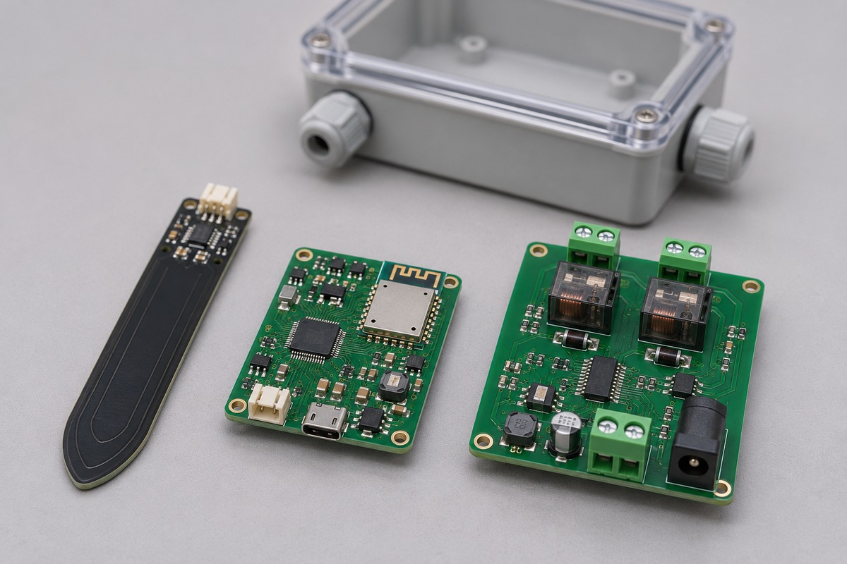
Soil moisture monitoring systems can use a probe PCB, a sensor-node PCB, a gateway or logger board, and a separate irrigation driver board. These functions may also share one assembly. The following are practical architecture options rather than fixed layer-count requirements.
Probe PCB
A PCB-based capacitive probe incorporates the sensing electrode geometry into the board. Copper dimensions, laminate, protective dielectric, and insertion depth can all affect the response. Changing the coating or board construction after calibration can alter the measurement relationship. A system using an external industrial probe may have no exposed sensing PCB at all.
Sensor-node PCB
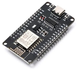
A rigid FR4 PCB can carry the MCU, analog front end, sensor connectors, radio, and power regulation. A simple circuit may fit on two layers. Four layers can provide more routing space and a continuous reference plane when measurement and wireless functions share a compact board. Layer count alone does not guarantee low noise.
Gateway or data-logger PCB
A gateway or logger may require more interfaces, memory, and processing than an individual sensor node. Its layout needs to accommodate the actual connector arrangement, communication modules, storage, and enclosure. Multilayer construction becomes useful as routing density and power-distribution requirements increase.
Irrigation driver PCB
A controller that operates valves or pumps adds relays, MOSFETs, connectors, and protection circuits sized for the load. Switching-current paths and inductive transients need to be managed so they do not disturb moisture measurements or reset the controller.
For manufacturing, the sensing area deserves particular attention. Coating exclusions, exposed electrodes, connector masking, and panel breakaway positions should follow the approved mechanical and electrical design.
How Are Soil Monitoring PCB Assemblies Tested for Outdoor Operation?
Testing should establish both electrical function and performance under the intended environmental conditions. Assembly inspection, sensor calibration, and enclosure testing answer different questions.
Assembly and interconnection
Bare-board electrical testing detects opens and shorts. After assembly, optical inspection and package-appropriate X-ray inspection help identify soldering defects. Functional checks then verify sensor channels, communication ports, and power rails. A visually acceptable solder joint does not establish measurement accuracy.
Measurement-chain performance
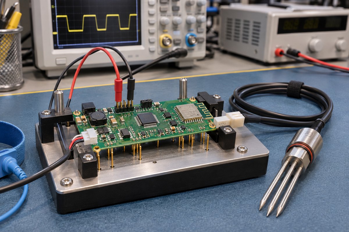
Known electrical inputs can verify the acquisition circuit independently of the probe. For example, a fixture for a specified 0–3.0 V input might apply 0.5 V, 1.5 V, and 2.5 V and compare the reported values with the calibrated source. These are illustrative test points; tolerances come from the product specification.
Soil calibration is a separate exercise using the probe, representative soil, and an appropriate reference method. Keeping these tests distinct helps identify whether an error originates in the electronics or the sensing conditions.
Power and radio operation
Measurements should cover sleep current, wake-up behavior, radio transmit bursts, low-battery operation, and recovery after power interruption. Sensor readings taken while the radio transmits or a valve switches can expose supply dips and coupled noise.
Humidity, temperature, and enclosure protection
Environmental validation evaluates the assembly over its specified operating conditions, including condensation where relevant. Conformal coating can help protect circuitry, but it does not seal cable entries or establish an enclosure IP rating. Water-ingress testing applies to the finished enclosure with its connectors, seals, and production assembly method.
Cable and connector faults
A disconnected or shorted probe should produce an identifiable fault rather than a believable moisture reading. External interfaces may also require ESD and transient testing appropriate to the installation. Test levels, exposure duration, and acceptance criteria belong to the agreed validation plan, not a universal soil-monitoring checklist.
EBest Circuit’s PCB Manufacturing and Assembly Capabilities
EBest Circuit supports custom boards through PCB fabrication, component sourcing, and SMT, THT, and mixed assembly. For soil-monitoring electronics, this allows the sensing circuit, wireless section, power components, and connectors to be coordinated within one manufacturing workflow.
| Manufacturing parameter | Capability | Conditions |
|---|---|---|
| FR4 layer count | 1–10 layers standard; 10–32 layers special | Stackup review required; high-Tg material required for 8 layers and above |
| Minimum trace/space, inner and outer layers | 4/4 mil standard; 3/3 mil special | 1 oz copper condition |
| Minimum finished hole diameter | 0.20 mm standard; 0.15 mm special | Subject to board construction |
| Maximum through-hole aspect ratio | 8:1 standard; 10:1 special | Board thickness to hole diameter |
| ENIG nickel thickness | 3–8 µm | ENIG finish |
| ENIG gold thickness | 0.025–0.125 µm | ENIG finish |
| Standard minimum 4-layer board thickness | 0.6 ± 0.1 mm | Maximum single-board size 350 × 400 mm for this listed condition |
| Minimum SMD component | 01005 package | Subject to component and assembly review |
| Minimum BGA pitch | 0.25 mm | Subject to package and process review |
| Assembly types | SMT, THT, mixed | According to the approved BOM and assembly drawings |
These capabilities are evaluated together for each build; individual limits are not a promise that every extreme can be combined on one board.
Our manufacturing support includes assembly review, component incoming inspection, solder-paste inspection, AOI, X-ray where applicable, and functional testing to an agreed procedure. For an OEM, that provides a route to evaluate board construction and assembly quality while retaining its own sensor calibration, firmware, and field-performance requirements.
FAQs About Soil Moisture Monitoring Systems
Can one soil moisture sensor represent an entire field?
Usually not where soil texture, elevation, crop rooting, or irrigation distribution varies. Sensors should represent the relevant management zones and root depths. A reading describes the soil around the probe, so placement matters as much as the number of measurement channels.
Can a probe be replaced without replacing the main PCB?
Yes, if the system uses a serviceable connector and supports the replacement probe’s supply, output, and protocol. The replacement may need new calibration coefficients. A matching connector alone does not prove that two probes are interchangeable.
What happens when the internet or cellular connection fails?
A system designed with local storage can continue recording and upload buffered readings after reconnection. Without that feature, the remote history may have gaps. Automatic irrigation also needs a defined local fallback so an unavailable network does not leave a valve in an unintended state.
What affects the cost of a soil monitoring PCB assembly?
Major factors include board size and layer count, radio and sensor-interface components, connector count, component availability, protection processes, and test time. Calibration fixtures and functional-test development can add initial costs, while repeated production can spread those setup costs across more units.
Can EBest Circuit assemble customer-supplied components?
Yes. We support consigned, partial-turnkey, and full-turnkey assembly. This allows customers to retain control of selected sensors or radio modules while arranging the remaining procurement and assembly around the approved BOM.
How long does PCB assembly take?
EBest Circuit’s assembly lead-time range is 1–5 days, subject to material availability, complete production files, process and test readiness, and confirmed scheduling. PCB fabrication, component procurement, and shipping add time to a full-turnkey order.
A dependable soil moisture monitoring system needs repeatable electronics behind every field reading. EBest Circuit combines PCB manufacturing with component management and in-house assembly, helping OEM teams coordinate fabrication, sourcing, and production through one partner. Whether the product uses an integrated probe or an external sensor interface, we can review the board build around its actual electrical and mechanical requirements. Contact sales@bestpcbs.com, or visit Contact Us and complete the form at the bottom of the page to discuss your prototype or production requirements.