A seat belt buckle switch detects whether the belt tongue is latched and provides an electrical signal to the vehicle’s monitoring system. In designs that use a PCB, the board carries contacts, sensing components, or signal-conditioning circuitry. Manufacturing must keep the electrical interface, board geometry, and buckle mechanism aligned so the assembled sensor can meet its specified switching requirements.
At EBest Circuit, we provide PCB manufacturing and assembly support for customer-designed sensing electronics. Our capabilities include FR4 fabrication, multiple surface finishes, SMT assembly, solder paste inspection, AOI, and X-ray inspection where the component package requires it. We review board and assembly requirements together to help resolve production issues before release. Request a manufacturing review for your buckle-switch PCB, or send your design files to sales@bestpcbs.com.
Seat Belt Buckle Switch PCB Types and Applications
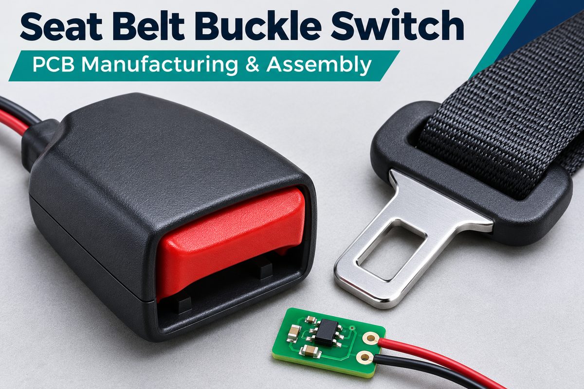
A seat belt buckle switch PCB supports detection of two basic states: latched and unlatched. Depending on the vehicle design, that signal can support belt reminders, restraint-system decisions, or electronic parking-brake logic; it does not independently control airbag deployment.
| PCB type | Function inside the assembly | Main production priority |
|---|---|---|
| Contact-pattern board | Conductive areas interact with a moving contact | Contact geometry, plating, and surface cleanliness |
| Hall-sensor board | Holds the sensing IC and associated circuitry | Sensor position, orientation, and solder quality |
| Interconnection board | Connects switch terminals, resistors, and external wires | Circuit integrity, resistor values, and terminal attachment |
Board thickness is a functional dimension. EBest Circuit’s regular process range is 0.4–3.5 mm for ENIG boards and 0.6–3.5 mm for HASL boards, subject to layer count and the complete construction. A 0.4 mm requirement therefore falls within the ENIG thickness range but outside the regular HASL range. This matters when the buckle housing leaves little vertical space.
Fit requires more than a small outline. A seat belt buckle with sensor needs defined locating edges, mounting holes, component-height limits, and wire exits. These features determine whether the electronics fit without interfering with the latch mechanism.
The PCB supports state detection; the mechanical buckle provides belt retention. Not every buckle switch contains a PCB, and the presence of a switch or wiring alone does not establish the internal board construction.
Seat Belt Buckle Sensor Selection: Mechanical Contact vs. Hall Effect
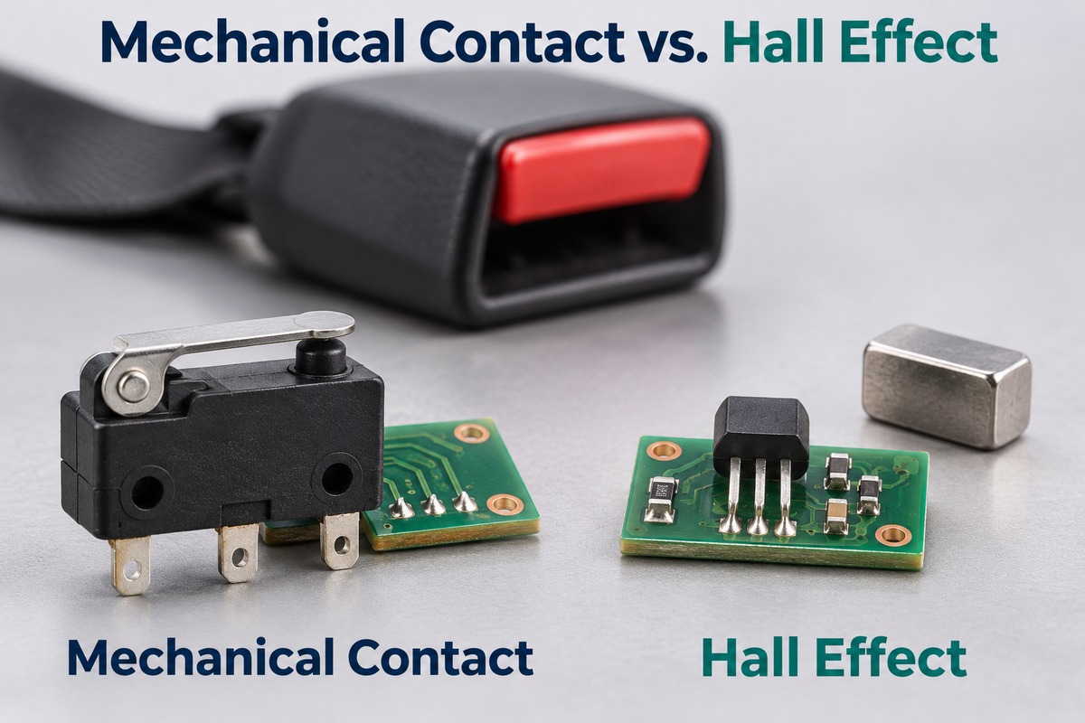
Choose between mechanical contact and Hall effect by comparing the electrical interface and positioning requirements. Published buckle-sensor specifications show why one production test cannot be used unchanged for both.
The figures below describe specific Littelfuse mechanical and Hall buckle-sensor designs. They illustrate interface differences and are not universal ratings for all seat belt sensors.
| Comparison item | Mechanical-contact example | Hall-effect example |
|---|---|---|
| Switching behavior | Normally open; closes when latched | Two current-output logic states |
| Electrical specification | Maximum switching voltage: 12 VDC | Powered magnetic sensing; supply must match the selected configuration |
| Current specification | Closed-state sensing current: 5–30 mA | Typical low output: 5.0 / 6.9 mA; typical high output: 12.0 / 17.0 mA |
| Operating temperature | −40°C to +85°C | −40°C to +85°C |
| Critical assembly relationship | Contact travel and engagement | Sensor orientation and magnetic geometry |
The slash-separated Hall values are reproduced as listed in the product specification; the exact configuration must be established before setting test limits. They are typical output levels, while the mechanical values specify a sensing-current range—these are different electrical quantities, not a direct power-consumption comparison.
For mechanical designs, review contact geometry, contact finish, and any resistor-coded circuit. If the PCB itself carries the moving-contact surface, solder-pad finish requirements alone are insufficient.
For Hall designs, review sensor orientation, magnet position, and placement relative to the housing datum. A continuity beep cannot confirm the specified current output. A sensor rated from −40°C to +85°C does not automatically qualify the entire PCBA over that range.
EBest Circuit can review the fabrication and assembly implications of the selected architecture, including footprint compatibility, component orientation, and test access.
Seat Belt Buckle Switch PCB Manufacturing Capabilities
EBest Circuit’s FR4 fabrication capabilities provide options for compact buckle-switch boards. The final process must be checked against the complete drawing, because material, thickness, hole geometry, and finish requirements interact.
| Manufacturing item | Available process reference | Relevance to the design |
|---|---|---|
| FR4 material | Standard, medium, and high-Tg options | Match the specified thermal and assembly requirements |
| Layer count | 1–10 layers in the regular process range | Select layers according to circuit and routing needs |
| ENIG board thickness | 0.4–3.5 mm regular process range | Confirm housing fit and assembly support |
| OSP board thickness | 0.4–3.5 mm regular process range | Check soldering and storage requirements |
| HASL board thickness | 0.6–3.5 mm regular process range | Confirm pad geometry and thickness compatibility |
| Finished hole diameter | 0.20 mm regular; 0.15 mm special process | Review vias and terminal holes together |
| Through-hole aspect ratio | Up to 8:1 regular; 10:1 special process | Check board thickness against hole diameter |
Boards above eight layers require high-Tg material within this regular process specification. Special-process values require engineering confirmation and should not be combined into a design without a manufacturability review.
For compact buckle electronics, the useful question is whether the board fits and functions within the specified assembly tolerances. A nominal outline dimension alone is insufficient: identify the mounting datum, critical hole locations, and any edges that locate the board inside the housing.
Materials and Surface Finishes for Seatbelt Buckle Sensor PCBs
Material and finish selection should reflect the board’s thermal requirements, soldering process, and contact function. A seatbelt buckle sensor PCB with soldered components has different surface requirements from a board that also carries sliding electrical contacts.
FR4 selection: Specify the laminate grade and required properties rather than requesting “automotive material” without a definition. Tg describes a material transition; it is not the assembly’s allowable continuous operating temperature.
Solderable finishes: ENIG, OSP, immersion tin, and other available finishes can be reviewed against the pad layout and assembly process. ENIG provides a flat solderable surface, while OSP requires attention to handling, storage, and the planned soldering sequence.
Switching surfaces: If a moving contact touches the PCB, define the plating system, thickness, contact area, and acceptance criteria explicitly. An ENIG solder-pad specification does not establish wear performance. Hard-gold finger capability likewise does not automatically qualify a different contact geometry.
Protective coating: Specify coating coverage and keep-out areas when coating is required. Electrical contacts, connector interfaces, and test points may need to remain accessible and free of coating.
PCB DFM for Seat Belt Sensors in Compact Buckles
DFM for seat belt sensors should check both board fabrication and the way the finished assembly fits inside the buckle. Resolving these interfaces before tooling helps avoid changes after the first build.
- Define the mechanical datum: Reference critical holes, slots, sensor locations, and board edges to the intended locating features. This makes the fit requirement measurable.
- Check component clearance: Include maximum component height, solder joints, wire exits, and clearance from moving parts. Review both sides of the board.
- Preserve sensing geometry: Identify contact zones or the Hall sensor’s required orientation. Share the relevant housing and magnet information when these affect placement acceptance.
- Plan panelization and separation: Provide space for assembly handling and fiducials. Keep breakaway features and separation stress away from sensitive components and functional edges.
- Provide test access: Reserve accessible connections for power, ground, and the required output measurements. Confirm access before the housing, coating, or wires restrict it.
The DFM review should end with a controlled drawing revision and resolved engineering questions. For locating features, approve the complete dimensional relationship rather than tightening unrelated tolerances across the entire board.
Seatbelt Buckle Sensor PCB Assembly Services
EBest Circuit supports SMT assembly and subsequent soldering operations for customer-defined sensor boards. Assembly preparation starts with a consistent BOM, component-location drawing, and placement-coordinate file.
Component and orientation review. Sensor part numbers, resistor values, connector pin numbering, and polarity must agree across the assembly files. Any proposed component substitution requires customer approval, especially when it can change the electrical output or magnetic response.
Soldering process preparation. Stencil design and reflow conditions are selected for the board and component requirements. Small boards may need a suitable panel or carrier to support printing, placement, and reflow.
Inspection during assembly. Solder paste inspection checks the printed deposits, while AOI checks visible component and solder features after assembly. X-ray inspection is available for hidden joints where the package and inspection plan justify it.
Secondary operations. Wire attachment, connector soldering, cleaning, coating, and depanelization should be included in the agreed scope where needed. Wire length, stripping dimensions, exit direction, and strain-relief requirements belong in the assembly documentation.
For a seatbelt buckle sensor, electrical inspection and positional verification serve different purposes. A correctly soldered sensor still needs to occupy the location and orientation required by the mechanical design.
Seat Belt Buckle Switch Testing and PCB Quality Control
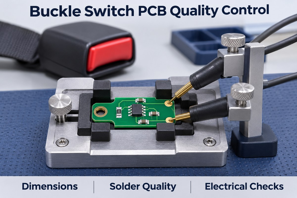
Seat belt buckle switch quality control should produce measurable results for circuit integrity, mechanical fit, soldering, and sensor output. A board can pass continuity testing yet still fail because its locating features or assembled sensor position do not match the buckle design.
Dimensional inspection starts with numerical limits. Relevant regular-process references from EBest Circuit’s FR4 capability table include:
| Inspection item | Regular-process reference | Inspection focus |
|---|---|---|
| Board outline dimension | ±5 mil (±0.127 mm) | Finished profile against the approved drawing |
| Non-plated hole diameter | ±2 mil (±0.0508 mm) | Diameter of specified locating or mounting holes |
| Plated hole diameter | ±3 mil (±0.0762 mm) | Finished hole diameter after plating |
For example, a 20.00 mm outline dimension with an approved ±0.127 mm tolerance has limits of 19.873–20.127 mm. This is a calculated inspection example, not a buckle product specification. Hole-diameter tolerance must not be treated as hole-position tolerance; locating relationships need their own drawing requirements.
Consistent results also depend on PCBA process control: managing solder-paste printing, component placement, and reflow conditions, with inspection data used to investigate deviations.
Electrical and assembly checks address separate defects:
- Bare-board electrical test: Check continuity and isolation against the approved circuit data before components obscure access.
- SPI and AOI: Inspect solder-paste deposits, visible placement, polarity, and solder features. These checks do not establish sensor functionality.
- X-ray where applicable: Inspect hidden solder joints when the selected package makes optical inspection insufficient.
- Functional test by agreement: Apply the specified supply and mechanical or magnetic stimulus, then record the measured output in both latched and unlatched states.
For a current-output Hall sensor, acceptance needs a minimum and maximum output window for each state. Typical datasheet values are not production pass/fail limits. For resistor-coded contacts, use the specified resistance windows rather than assuming every closed switch should read zero ohms.
The quotation should identify fixture responsibility, test coverage, and any required result records. Mechanical cycling, environmental qualification, and vehicle-system validation remain separate from routine PCB and solder-joint inspection.
Seat Belt Buckle Sensor PCB Production Lead Time
For an initial schedule, EBest Circuit’s standard FR4 prototype references are 7 days for one layer, 8 days for two layers, and 10 days for four layers. These are bare-board reference times; a finished seat belt buckle sensor PCBA also depends on component readiness, assembly, and the agreed testing scope.
| Standard FR4 prototype | Normal service | Fastest service, subject to confirmation |
|---|---|---|
| 1 layer | 7 days | 24 hours |
| 2 layers | 8 days | 24 hours |
| 4 layers | 10 days | 48 hours |
These references apply to prototype orders below 1 m², using standard FR4, 0.4–1.6 mm thickness, H/H or 1 oz copper, lead-free HASL, green solder mask, and white silkscreen. Additional conditions include trace width/spacing greater than 8 mil, holes greater than 0.3 mm, and annular rings greater than 10 mil.
ENIG, specialized contact plating, smaller features, or different construction require a separate schedule review. The fastest bare-board option is not a complete PCBA delivery promise.
Plan the assembled-board schedule around the last prerequisite to become ready: bare boards, the full component kit, approved assembly data, and any functional-test fixture. Assembly, inspection, and shipment preparation follow that readiness point; transit time is separate.
To confirm a production schedule for your buckle-switch PCB or PCBA, send us your delivery requirements or email sales@bestpcbs.com. Include your board revision, BOM, quantity, test scope, and target delivery date so we can assess fabrication and assembly timing together.
Why Choose EBest Circuit for Buckle Switch PCB Manufacturing?
EBest Circuit brings PCB fabrication and assembly support into the same project discussion. This helps buyers resolve the interfaces between the bare board, populated assembly, and production documentation before release.
- PCB and assembly coordination: Reviewing fabrication and placement requirements together helps align panel design, finish selection, and assembly handling.
- Material and finish options: FR4 grades and multiple surface treatments allow the manufacturing proposal to follow the drawing’s actual requirements.
- Assembly process inspection: SPI, AOI, and package-appropriate X-ray inspection provide checks at different production stages, supporting investigation of assembly defects.
- Support for secondary operations: Soldering, cleaning, coating, and depanelization capabilities can be incorporated into the agreed build scope, reducing separate processing handoffs.
- Engineering review before release: Checking drawings, BOM data, and assembly files helps expose conflicting requirements before materials and tooling are committed.
- Project-specific test planning: Defining the required measurements and fixture responsibilities during quotation gives both teams a clearer acceptance basis for delivery.
Share any required automotive quality approvals, customer-specific documentation, and qualification obligations with the initial RFQ so their applicability and availability can be confirmed before supplier approval.
How to Request a Buckle Switch PCB and Assembly Quote
A complete RFQ should define the bare board, assembled configuration, and acceptance requirements. Matching file revisions are especially important when the sensor circuit and buckle housing are being developed together.
If your files contain confidential design information, review the PCB NDA considerations before sharing manufacturing files and discuss confidentiality arrangements before submitting the complete package.
Please include:
- PCB fabrication files: Gerber and drill data, fabrication drawing, stack-up, material, copper thickness, finish, and dimensional tolerances.
- Assembly files: BOM with manufacturer part numbers, placement coordinates, assembly drawings, and approved alternatives.
- Mechanical interface details: Housing envelope, mounting references, component-height limits, and contact or sensor positioning requirements.
- Test requirements: Electrical interface, operating states, output limits, test procedure, and available fixture or reference samples.
- Order and delivery information: Prototype quantity, expected repeat quantities, requested delivery date, packaging, and required reports.
State whether the request covers bare PCBs, populated boards, or additional wire and connector work. If some details remain under development, identify them explicitly so the quotation can separate confirmed requirements from open items.
FAQs About Seat Belt Sensors and Buckle Switch PCBs
Does every seat belt buckle switch contain a PCB?
No. Buckle switches can use different internal constructions. A PCB is relevant where the design needs a contact pattern, mounted sensing electronics, or an interconnection platform.
Are seatbelt buckle sensor and seat belt buckle sensor different products?
The spelling variation does not define a different product. Compare the sensor technology, dimensions, electrical interface, and application specification to establish compatibility.
How to test seat belt buckle switch assemblies during production?
Use a fixture that reproduces the specified operating states and measures the required output against approved limits. Contact-based and powered Hall-sensor designs need different test methods; the procedure must match the actual circuit.
Can a resistor value be changed without updating the assembly requirements?
A resistor may form part of the output coding or diagnostic circuit. Any value change needs design approval and a corresponding BOM update, with test limits reviewed where affected.
Can the same PCB be used with a different Hall sensor?
Only after checking the footprint, pinout, supply requirements, output behavior, and magnetic characteristics. A mechanically compatible package does not establish electrical or sensing equivalence.
Should test requirements be supplied before the prototype build?
Yes. Early test requirements allow the team to review test access and fixture needs while board or panel changes are still practical. They also establish what the prototype results must demonstrate.
Bring your seat belt buckle switch drawing, BOM, and acceptance requirements to EBest Circuit for a coordinated PCB and assembly review. We can assess fabrication options, assembly operations, and the proposed inspection scope around your design, then prepare a quotation and production schedule for the defined build. Request a quote for your buckle-switch PCB and assembly project, or email your project files and quantities to sales@bestpcbs.com.