A thermistor symbol represents a resistor whose resistance changes with temperature. Recognizing it helps you understand whether a circuit monitors heat, compensates for temperature changes, or limits current. The basic shape identifies a temperature-dependent resistor, while nearby labels and the component specification explain whether it is an NTC or PTC device.
EBest Circuit (Best Technology) supports PCB fabrication, component sourcing, and assembly for temperature-monitoring, control, and power electronics. Bringing these stages together helps carry the specified thermistor and its mounting requirements from the BOM into the assembled board. For a PCB or PCBA project using thermistors, contact sales@bestpcbs.com.
What Does a Thermistor Symbol Look Like?
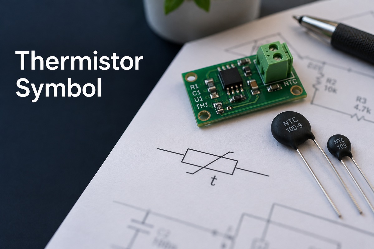
A common thermistor symbol combines a resistor body with a diagonal temperature-dependence mark. The resistor may appear as a rectangle or a zigzag, depending on the drawing convention. Many rectangular versions use a diagonal stroke with a short bent end; some drawings add a temperature notation such as t or θ.
The distinguishing feature is the temperature-related mark added to the resistor. A plain rectangle or zigzag alone normally represents an ordinary resistor. The outline can therefore vary without changing the component’s basic function.
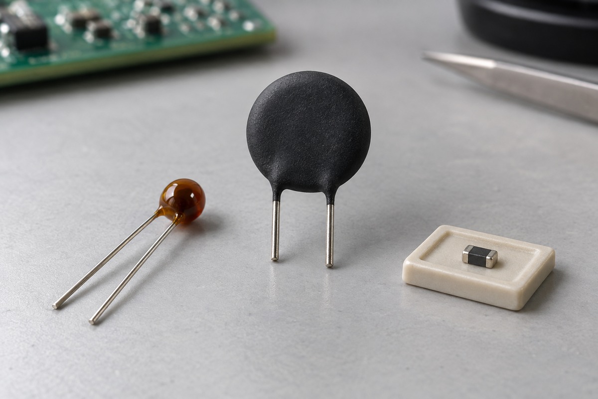
A schematic symbol describes electrical behavior rather than physical appearance. A small surface-mount chip, a coated bead, and a leaded disc can all be thermistors, even though their circuit symbols look similar. Likewise, a thermistor drawn beside an IC may actually be mounted elsewhere on the PCB or connected through a cable.
NTC Thermistor Symbol vs. PTC Thermistor Symbol
NTC and PTC describe opposite directions of resistance change. An NTC thermistor decreases in resistance as its temperature rises; a PTC thermistor increases in resistance over its specified operating region.
| Type | Meaning | Resistance as temperature rises | Possible schematic identification |
|---|---|---|---|
| NTC | Negative temperature coefficient | Decreases | NTC label or a negative temperature-coefficient notation |
| PTC | Positive temperature coefficient | Increases | PTC label or a positive temperature-coefficient notation |
Some schematics use the same generic thermistor symbol for both types. In that case, the part number or accompanying component description identifies the behavior. The angle of the diagonal line alone is not a reliable way to distinguish NTC from PTC.
A plus or minus sign used to describe the temperature coefficient refers to the direction of resistance change. It does not identify positive and negative terminals.
The distinction matters when reading a circuit. Replacing an NTC sensing element with a PTC device would reverse the resistance response to heat. Even within one type, components can have different resistance curves: two NTC thermistors with the same room-temperature resistance are not necessarily interchangeable across the operating temperature range.
Thermistor vs. Variable Resistor and LDR Symbols
These symbols all build on a resistor shape, but their added marks identify different causes of resistance change. The most useful distinction is temperature, adjustment, or light.
| Component | Common visual clue | What changes the resistance? |
|---|---|---|
| Thermistor | Temperature-dependence stroke, sometimes with a temperature notation | The thermistor’s temperature |
| Variable resistor | An arrow crossing or pointing to the resistor body | Adjustment of a movable contact |
| Potentiometer | A wiper connection leading to the resistor, usually with three terminals | Wiper position |
| LDR or photoresistor | Arrows pointing toward the resistor, sometimes inside a circle | Incident light |
A thermistor’s diagonal mark can resemble the line through a variable resistor at a glance. The arrowhead and wiper connection are useful clues for an adjustable resistor. On an LDR, the incoming arrows represent light rather than electrical terminals.
For example, a variable resistor in a temperature-control circuit may set the temperature threshold, while a nearby thermistor senses temperature. They can affect the same control function but perform different jobs. Treating both as adjustable resistors would obscure how the circuit responds to heat.
What Do the Numbers Beside a Thermistor Symbol Mean?
Numbers near the symbol usually describe resistance or identify the component. They do not, by themselves, state the temperature being measured.
A 10 kΩ rating specifies resistance at a reference temperature. If an NTC is marked R25 = 10 kΩ, its nominal resistance is 10,000 ohms at 25°C. It will have a different resistance at other temperatures. A bare “10K” label gives less information, so its reference temperature comes from the component specification.
A tolerance applies to a defined parameter. A rating such as R25 = 10 kΩ ±1% describes the permitted resistance variation at 25°C. It does not mean that the assembled circuit measures temperature to ±1°C or ±1%.
The B value describes an NTC’s resistance–temperature characteristic. A notation such as B25/85 identifies a beta value determined using 25°C and 85°C. It is expressed in kelvins. A larger B value generally indicates a steeper resistance change for the same nominal resistance over the relevant range; it is not a maximum operating temperature.
These distinctions explain why a replacement marked “10K NTC” may produce a different temperature reading. Matching the nominal resistance alone does not match the complete resistance curve. The sensing circuit’s conversion method must correspond to the fitted thermistor’s characteristics.
How Does a Thermistor Work in a Temperature-Sensing Circuit?
A thermistor often forms a voltage divider with a fixed resistor. As temperature changes its resistance, the divider produces a changing voltage that an ADC or comparator can read.
Consider a fixed resistor connected from a 3.3 V supply to a sensing node, with an NTC connected from that node to ground. For an ideal divider with negligible input loading:
Vout = Vsupply × RNTC / (Rfixed + RNTC)
If both resistances are 10 kΩ, the node voltage is 1.65 V. If heating reduces the NTC resistance to 5 kΩ, the voltage becomes 1.10 V. These are illustrative resistance values; the temperature corresponding to 5 kΩ depends on the particular thermistor.
With this arrangement, heating lowers the output voltage. If the NTC and fixed resistor exchange positions, heating raises the output voltage instead. The same NTC behavior can therefore produce either voltage direction, depending on where it sits in the divider.
The controller converts the voltage into resistance and then into temperature using an appropriate resistance–temperature table or model. Because an NTC’s response is nonlinear, a fixed number of ADC counts does not generally represent the same temperature change across the full range.
The thermistor also dissipates power when current flows through it. Excessive sensing current can warm the component and shift its reading above the temperature it is intended to measure. Thermal placement matters for the same reason: a thermistor close to a power resistor may respond strongly to that local heat source, even when the surrounding air is cooler.
Thermistor Uses in Temperature Sensing and Circuit Protection
Thermistors can measure temperature or use their own heating to influence current. The application depends on the component’s construction and ratings, not just the symbol on the schematic.
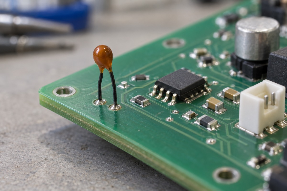
Temperature sensing and control. NTC thermistors commonly provide temperature feedback in battery packs, power supplies, HVAC equipment, and electronic assemblies. Their changing resistance can support fan control, charging limits, or an overtemperature response. Thermal contact determines what is being sensed: a device attached to a battery cell responds differently from one exposed to air on the PCB.
Inrush current limiting. A power NTC placed in series with a supply has a relatively high resistance when cold. This reduces the initial charging current into capacitors. As current heats the NTC, its resistance falls, reducing its voltage drop during operation. A rapid restart while the device is still hot can provide less inrush limiting because it has not recovered its cold resistance.
Overcurrent protection. A PTC intended for protection heats as current flows. Its rising resistance limits current, and suitable switching types show a pronounced increase near their transition region. Recovery depends on the device cooling and on the conditions in the surrounding circuit. This behavior differs from a fuse that opens permanently.
A small NTC temperature sensor is not a substitute for a power-rated inrush limiter. Similarly, a PTC temperature-sensing device is not automatically suitable as a resettable protector. The symbol identifies a temperature-dependent resistance; the component specification establishes which of these jobs it can perform.
FAQs About Thermistor Symbol
Does a thermistor have polarity?
A conventional two-terminal thermistor is non-polarized. Reversing its two leads does not reverse its resistance–temperature behavior. A sensor module containing additional electronics may have supply and signal connections that must be connected in the specified direction.
What do TH and RT mean beside a thermistor symbol?
They may be reference-designator prefixes used to identify thermistors in a particular schematic. Naming conventions vary between projects and CAD libraries. A designator such as TH1 identifies a component instance; its value and part number provide the electrical details.
Does the symbol tell you whether the thermistor is surface-mount or through-hole?
No. The same electrical symbol can be associated with different packages. The assigned footprint and part number identify the physical device, including its pads or leads and mounting dimensions.
Is a thermistor the same as a thermocouple?
No. A thermistor changes resistance with temperature and needs an electrical measurement circuit. A thermocouple produces a small voltage related to the temperature difference between its sensing and reference junctions. They use different symbols and measurement methods.
How can you identify NTC or PTC when the schematic only shows a generic symbol?
The part number and its resistance–temperature data provide the clearest answer. For a suitable isolated component, measuring resistance at two known temperatures can indicate the direction of change. An in-circuit reading may include parallel paths, so it can misrepresent the thermistor’s resistance.
Once a thermistor symbol is linked to the correct component and circuit function, that specification needs to carry through into the physical assembly. EBest Circuit supports PCB fabrication and PCBA for thermistor-based monitoring and control boards, including component sourcing and assembly to the approved design. Contact sales@bestpcbs.com to discuss prototype or production assembly for your board.