PCB manufacturing PCB manufacturing
Home > Blog

pcb programming

Practical IC Programming Guide for PCBA Assembly and Testing
Friday, July 31st, 2026

IC programming is the process of loading firmware, configuration data, or code into an integrated circuit so the assembled product can perform its intended function. In PCB assembly, this step often applies to microcontrollers, memory chips, programmable logic devices, and other programmable ICs used in embedded products.

For engineers and buyers, the real concern is not only “Can this chip be programmed?” It is whether the programming file, IC model, PCB footprint, programming interface, fixture, verification method, and functional test plan can work together during PCBA production. EBest Circuit (Best Technology) supports PCB fabrication, component sourcing, SMT assembly, IC programming coordination, inspection, testing, and small-batch production. If your project needs IC programming during PCBA assembly, please send your Gerber files, BOM, CPL, firmware file, programming notes, and test requirements to sales@bestpcbs.com for engineering review before production.
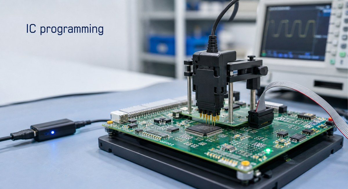
IC programming
IC programming in PCBA production uses programming fixtures, approved firmware files, and verification steps.

What Is IC Programming in PCB Assembly?

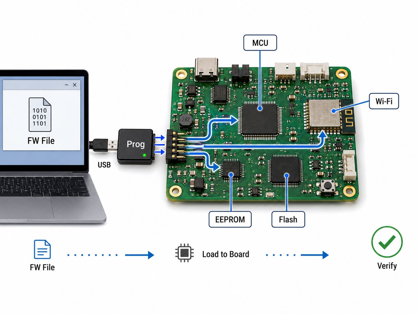
IC programming in PCB assembly means loading customer-provided data or firmware into a programmable IC before shipment or during the PCBA process.

In a PCBA project, IC programming may happen:

  • before SMT, when blank ICs are programmed first
  • after SMT, when the assembled board is programmed through a connector or test pads
  • during functional testing, when programming and verification are combined
  • during rework, when a firmware version needs to be updated

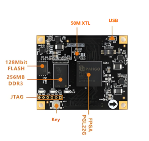
Common programmable ICs include microcontrollers, EEPROM, Flash memory, CPLD, FPGA, and selected communication or control ICs.

The PCB assembly supplier should not create the firmware logic. That belongs to the customer’s engineering team. The supplier’s role is to follow the approved programming file, programming method, fixture requirement, verification step, and production note.

For projects that also involve board-level programming, our related guide on how to program a PCB board explains the broader PCBA programming workflow.

Integrated Circuit Programming vs PCB Programming

Integrated circuit programming and PCB programming are closely related, but they are not always the same thing.

TermPractical Meaning
Integrated circuit programmingLoading data into a specific IC
PCB programmingProgramming an assembled board through the PCB interface
Firmware loadingLoading customer firmware into a device
Functional programmingProgramming followed by board-level function check

For example, an EEPROM may be programmed before assembly. A microcontroller may be programmed after SMT through SWD, JTAG, UART, USB, or test pads. A complete control board may need programming plus functional testing before shipment.

This distinction matters because the production plan changes depending on when the IC is programmed.

If the IC is programmed before SMT, the supplier must control labels, part separation, orientation, and moisture handling. If programming happens after SMT, the PCB must provide access to programming pads, connectors, or fixtures. If programming is part of final test, the test procedure must define pass/fail criteria clearly.

Which ICs Need Programming Before or After Assembly?

Not every IC needs programming. Some components are fixed-function devices. Others must receive firmware, configuration data, calibration data, serial numbers, or customer-specific settings.

Common ICs that may need programming include:

  • microcontrollers
  • EEPROM and Flash memory
  • CPLD and FPGA devices
  • programmable logic ICs
  • motor control ICs with configuration memory
  • communication modules
  • sensor modules with calibration data
  • power management ICs with configurable settings

Before-assembly programming is useful when:

  • the IC cannot be accessed after assembly
  • the board has no programming connector
  • the customer wants programmed parts placed directly
  • the production process uses pre-programmed IC labels

After-assembly programming is useful when:

  • the board has programming pads or connectors
  • the firmware version may change late in the project
  • the product needs board-level verification after programming
  • the same hardware supports multiple firmware versions

For PCBA projects, the safest approach is to confirm the programming stage before SMT starts. A board that is already assembled but has no accessible programming interface can create avoidable rework.

IC Programming Files Customers Should Provide

For IC programming to run smoothly, the programming information must be clear before production.
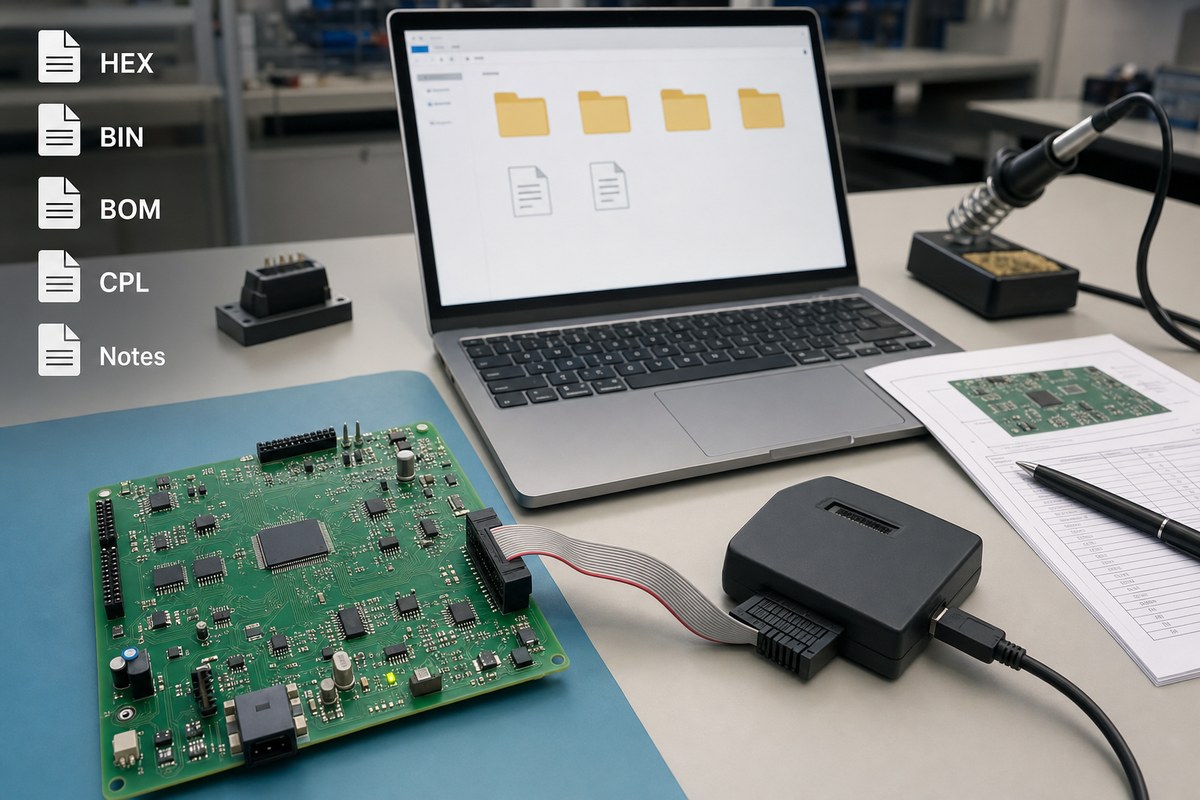
IC programming
Programming preparation should connect firmware files, BOM, CPL, board revision, and production notes.

Useful files and notes include:

  • firmware file, such as HEX, BIN, ELF, or other approved format
  • exact IC part number
  • BOM and approved alternates
  • programming method
  • programming voltage and interface notes
  • checksum or verification requirement
  • firmware version number
  • security or lock-bit instructions
  • label and traceability requirement
  • functional test procedure
  • pass/fail criteria
  • special handling notes

A file name alone is not enough. For example, `final.hex` does not tell the production team which IC it belongs to, which board revision it matches, or whether the chip should be locked after programming.

A better programming note would include the IC model, board revision, firmware version, programming interface, verification method, and required output label.

If component sourcing is included, the BOM should also show whether ICs are blank, pre-programmed, customer-supplied, or manufacturer-sourced. This is especially important for turnkey PCBA projects involving component sourcing.

IC Programming Methods in PCBA Production

IC programming can be handled in different ways depending on the chip, board layout, quantity, and test requirement.

MethodTypical Use
Offline programmingIC programmed before assembly
In-system programmingIC programmed after assembly
Fixture programmingBoard programmed through test pads
Connector programmingBoard programmed through USB, JTAG, SWD, UART, or other port
Functional test programmingProgramming combined with final test

Offline programming is useful for simple ICs or parts that are hard to access after assembly. In-system programming is common for microcontroller boards because the firmware can be loaded after the board is assembled.

Fixture programming is useful when the product has test pads but no external programming connector. In this case, pad size, pad location, fixture access, and board support must be reviewed before production.

The programming method should be selected by the customer’s engineering team. EBest Circuit can review whether the PCB files, assembly process, fixture access, and testing notes support that approved method.

IC Programming Setup for PCBA Production

A reliable IC programming setup is more than a programmer device. It is a controlled production step.

The setup should define:

  • programming software version
  • programmer model or approved equipment
  • adapter, socket, cable, or fixture
  • IC orientation
  • board power condition
  • connection method
  • firmware version
  • verification step
  • pass/fail output
  • label or record requirement

For assembled boards, the physical access matters. Programming pads should not be blocked by tall components. Test points should not be too small or too close together. If a bed-of-nails fixture is used, the board should have enough support so pogo pins do not bend the PCB during contact.

For boards with BGA, fine-pitch ICs, or dense layouts, programming access should be reviewed together with SMT and inspection requirements. If the project includes complex assembly, BGA assembly and X-Ray inspection may also be part of the production plan.

How to Program an IC During PCBA Assembly

A practical IC programming flow during PCBA assembly usually follows a controlled sequence.

Typical flow:

  • Review customer files and programming notes.
  • Confirm the programmable IC part number and board revision.
  • Check whether programming happens before or after SMT.
  • Prepare firmware file, programmer, cable, fixture, or adapter.
  • Build and inspect the PCBA.
  • Power the board under the approved condition.
  • Load the firmware or data into the IC.
  • Verify checksum, readback, or software confirmation.
  • Run functional test if required.
  • Record version, label, and packing notes.

The most common problems happen when one step is unclear. The IC may be correct, but the firmware version may not match the board revision. The programming port may exist, but the connector may be blocked after enclosure assembly. The board may program successfully, but functional testing may fail because the test procedure is incomplete.

For prototype and small-batch PCBA, the goal is not only to program the IC. The goal is to confirm that the board can be programmed repeatedly, inspected clearly, and tested before delivery.

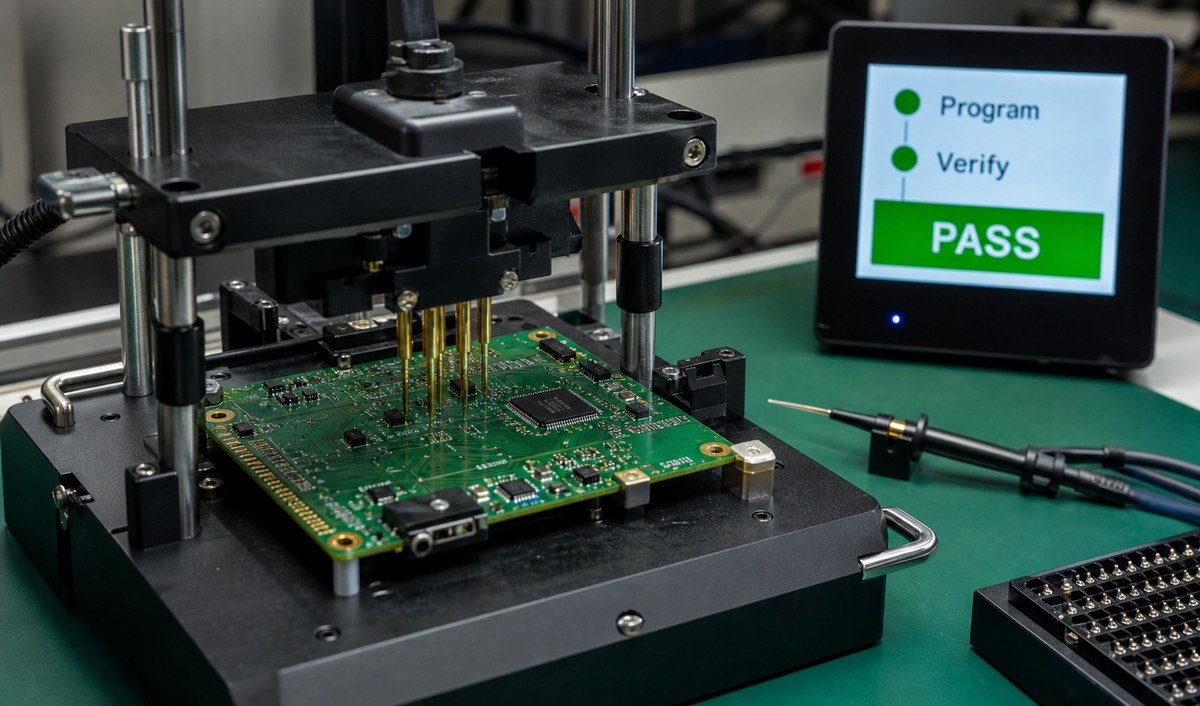
Programmed IC Verification and Functional Testing

Programming is not complete until the result is verified.
IC programming
Programmed IC verification and functional testing help confirm the board is ready before delivery.

Useful verification methods include:

  • checksum verification
  • readback comparison
  • programmer software confirmation
  • power-on check
  • LED or display response
  • communication test
  • sensor or input/output test
  • current consumption check
  • customer-defined functional test

For production, verification should be documented clearly. A message that says “programming successful” may not be enough if the customer also requires communication, calibration, output control, or serial number confirmation.

For PCBA projects, EBest Circuit can coordinate programming with inspection and testing requirements. Depending on the project, this may include AOI, X-Ray, visual inspection, electrical testing, functional testing, labeling, and packing.

This is useful for prototype PCB assembly because early builds often reveal whether the programming interface, firmware version, test fixture, and final inspection method are ready for the next production stage.

IC Programming Services Case Study for a PCBA Project

A European customer needed a small-batch PCBA for an industrial control product. The board used a programmable microcontroller, several communication interfaces, connectors, and customer firmware that had to be loaded after SMT assembly.

Project requirements:

  • Customer region: Europe
  • Application: industrial control module
  • Build stage: prototype to small-batch validation
  • PCB type: multilayer FR4 PCBA
  • Assembly: SMT plus connector assembly
  • Programming: customer-provided firmware loaded after SMT
  • Testing: programming verification and functional test
  • Packing: single-board protection for delivery

Main challenge:

The board itself was not difficult only because of SMT. The real risk was the handoff between files, components, programming, testing, and shipment. If the firmware version, board revision, connector direction, programming pads, or test steps were unclear, the customer could receive boards that looked complete but were not ready for system validation.

EBest Circuit’s production support:

  • Reviewed Gerber, BOM, CPL, and assembly drawing together.
  • Confirmed the microcontroller part number and programming interface.
  • Checked connector orientation and programming access before SMT.
  • Loaded the customer-provided firmware after assembly.
  • Verified the programming result before functional test.
  • Kept firmware version and packing notes visible until shipment.

Result:

The customer received programmed PCB assemblies ready for engineering validation. The useful value was not only loading firmware into the IC. It was keeping PCB fabrication, SMT assembly, IC programming, testing, and delivery notes connected in one workflow.

For customers comparing IC programming services, this kind of coordination reduces the risk of “assembled but not usable” boards.

FAQs About IC Programming

1. What is IC programming? IC programming is the process of loading firmware, data, or configuration information into an integrated circuit, such as a microcontroller, EEPROM, Flash memory, CPLD, or FPGA.

2. Is IC programming the same as PCB programming? Not exactly. IC programming focuses on a specific chip. PCB programming usually means programming the assembled board through a connector, test pads, or programming interface.

3. Can EBest Circuit write the firmware for my IC? No. The firmware logic and program content should come from the customer’s engineering team. EBest Circuit can help load customer-provided firmware during PCBA assembly and coordinate verification or functional testing.

4. What files are needed for IC programming? Common files include HEX, BIN, or another approved programming file, plus IC part number, board revision, programming method, checksum requirement, firmware version, and test instructions.

5. Should IC programming happen before or after SMT assembly? It depends on the IC, PCB layout, programming access, firmware stability, and test plan. Some ICs are programmed before assembly. Many microcontroller boards are programmed after SMT through a connector, pads, or fixture.

All in all, IC programming should be planned as part of the PCBA production path, not treated as a last-minute task after assembly. If your project needs IC programming, firmware loading, programming pads, test fixtures, functional testing, or small-batch PCBA support, please send your Gerber files, BOM, CPL, firmware file, and programming notes to sales@bestpcbs.com. EBest Circuit can help review whether the manufacturing and assembly path is ready before production starts.
You may also like

How to Program a PCB Board | PCBA Programming Guide
Friday, July 17th, 2026

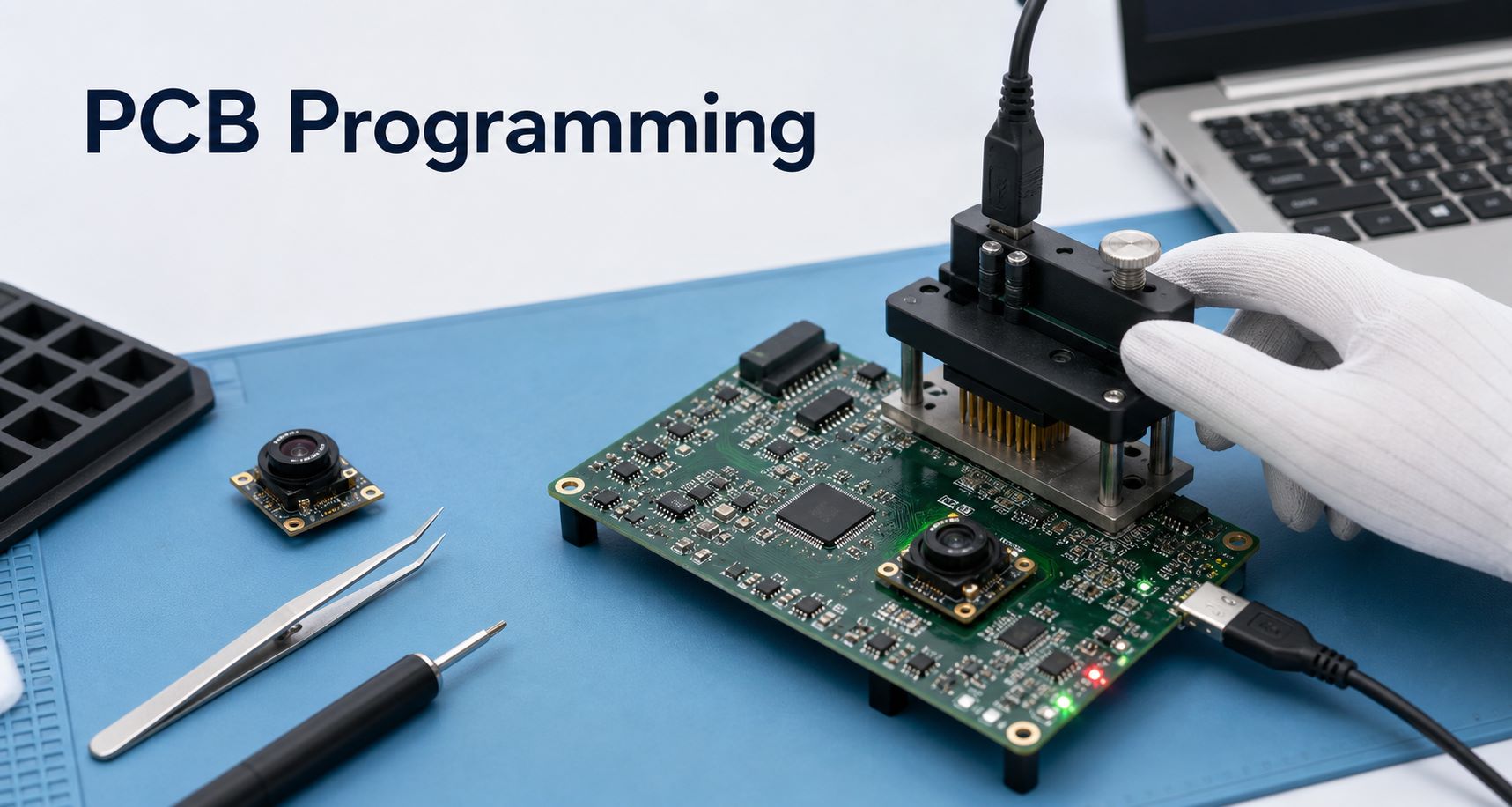
When engineers search how to program a PCB, they usually do not mean programming the bare circuit board itself. A PCB is not programmed directly. What gets programmed is the MCU, IC, EEPROM, memory device, wireless module, camera module, or other programmable component assembled on the PCB.

In real PCBA production, PCB programming usually means loading customer-approved firmware or software into assembled boards, then checking whether the programmed PCBA works according to the customer’s test method. EBest Circuit (Best Technology) supports PCB fabrication, component sourcing based on approved BOM, PCBA assembly, firmware flashing based on customer-provided files, functional testing coordination, packing, and production traceability. If you have a PCB or PCBA project that needs programming support, pls feel free to send your Gerber files, BOM, firmware file, programming instructions, test method, or assembly notes to sales@bestpcbs.com for engineering review before production.

how to program a pcb

What Does PCB Programming Mean?

PCB programming means loading software, firmware, bootloader data, configuration files, or memory data into programmable components on a PCB assembly.

Common programmable parts include:

  • MCU
  • PIC microcontroller
  • EEPROM
  • Flash memory
  • FPGA
  • Wireless module
  • Sensor module
  • Power management IC
  • Camera control IC
  • Bluetooth or Wi-Fi module

The PCB provides the physical circuit, power, signal paths, connectors, test points, and programming interface. The firmware file is usually prepared by the customer’s software or embedded engineering team.

A PCB manufacturer or PCBA assembler may help with programming during production, but that does not mean the factory writes the firmware. The factory loads the approved file, follows the customer’s programming method, and verifies the board according to the approved test procedure.

how to program a pcb

How to Program a PCB Board During PCBA Assembly

To program a PCB board during PCBA assembly, the process usually starts after SMT assembly and inspection. The board must first be assembled correctly before firmware flashing can be done reliably.

A typical PCBA programming workflow includes:

  • PCB fabrication
  • Component sourcing based on approved BOM
  • SMT assembly
  • AOI or visual inspection
  • IC or MCU programming
  • Programming result check
  • Functional testing
  • Version record and batch traceability
  • Packing and shipment

The programming step may happen through a programming connector, test pads, USB interface, SWD, JTAG, UART, ISP, or a custom fixture. The exact method depends on the customer’s circuit design and programming instructions.

For production, the programming file version must be clearly controlled. If different firmware versions are mixed, the product may pass assembly inspection but fail in the customer’s final system.

How to Program a Custom PCB with Customer Firmware

To program a custom PCB, the customer usually needs to provide the required firmware and production instructions. The PCBA supplier should not guess the firmware version, modify the code, or change the programming method without approval.

For a custom PCB programming project, customers should prepare:

  • Gerber or ODB++ files
  • BOM
  • Pick and place file
  • Assembly drawing
  • Firmware file
  • Programming tool or method
  • Programming connector definition
  • Test procedure
  • Pass/fail criteria
  • Firmware version requirement
  • Packing and labeling requirements

EBest Circuit can support firmware flashing based on customer-provided files. If the customer requires basic functional testing after programming, the test method should be confirmed before production.

For example, a programmed board may need to power on correctly, show LED status, connect through USB, display a camera image, communicate with a module, read a sensor, or pass a current consumption check. These checks should be defined by the customer and confirmed before mass production.

Can You Program a PCB Board with a Gerber File?

No. A Gerber file cannot program a PCB board.

A Gerber file is used to manufacture the bare PCB. It defines copper layers, solder mask, silkscreen, drill holes, board outline, and other PCB fabrication information. It does not contain firmware, software, or executable code.

A Gerber file can help the PCB factory make the board. To program the assembled board, you also need a firmware file or software file, plus a programming method.

In simple terms:

File TypePurpose
Gerber / ODB++PCB fabrication
BOMComponent sourcing
Pick and placeSMT assembly
Firmware fileIC or MCU programming
Test procedureFunctional verification

This is why PCB programming should be planned together with PCBA assembly. The PCB must include the correct programming connector, test pads, or access points before production.

How to Program a PCB Board with a USB Interface

Some PCB boards can be programmed through USB if the circuit supports it. This may be done through a USB bootloader, USB-to-UART bridge, MCU USB interface, or a customer-defined programming tool.

A USB programming process may include:

  • Connect the PCBA to a computer
  • Put the board into bootloader or programming mode
  • Open the customer-approved programming software
  • Select the correct firmware file
  • Flash the firmware
  • Verify programming success
  • Run a basic functional test

For production, USB programming can be convenient, but it still requires clear instructions. The factory needs to know the correct cable, software tool, driver, firmware version, programming sequence, and pass/fail standard.

If USB is also used for product operation, the customer should define whether the test is only for firmware loading or also for communication verification.

How to Program a PIC Microcontroller on a PCB

A PIC microcontroller on a PCB can usually be programmed through an ICSP interface or another customer-defined programming method. The PCB must include the correct access points for programming signals, power, ground, and reset or control lines.

For a PIC microcontroller programming project, the customer should confirm:

  • PIC part number
  • Programming interface
  • Pin definition
  • Programming voltage
  • Firmware file
  • Programmer model
  • Programming software
  • Verification method
  • Functional test requirement

For PCBA production, accessibility matters. If programming pads are too small, blocked by components, or difficult to contact with a fixture, programming may become slow or unreliable. This should be reviewed before mass production.

EBest Circuit can support the assembly and programming process according to customer-provided files and instructions, but firmware development and code debugging should remain with the customer’s embedded software team.

Programming Connectors, Test Points, and PCBA Fixtures

Programming access should be considered before PCB fabrication. If the board has no accessible connector or test pads, programming after assembly may become difficult.

Common programming access methods include:

  • Pin header
  • Tag-Connect style pads
  • Test pads
  • USB port
  • SWD connector
  • JTAG connector
  • UART pads
  • Bed-of-nails fixture
  • Custom PCBA test fixture

For prototype builds, engineers may use a connector or manual cable. For larger production, a fixture is often better because it improves speed, consistency, and operator efficiency.

A well-designed PCBA programming setup should ensure uninterrupted contact, minimize manual handling, protect the board from mechanical damage, and provide clear programming results.

PCB Programming Checks Before Mass Production

Before mass production, PCB programming should be verified with a small pilot run. This helps catch problems before a large batch is assembled.

Important checks include:

  • Is the firmware version correct?
  • Is the programming interface accessible?
  • Does the programming tool work consistently?
  • Is the programming time acceptable?
  • Is the pass/fail result clear?
  • Can the board be tested after programming?
  • Are labels or QR codes needed for traceability?
  • Is the customer’s test procedure complete?
  • Are failed boards handled correctly?
  • Is the packing method suitable after testing?

For programmed PCBA products, traceability is important. The production team should know which firmware version was loaded, which batch was programmed, which test method was used, and whether the product passed inspection.

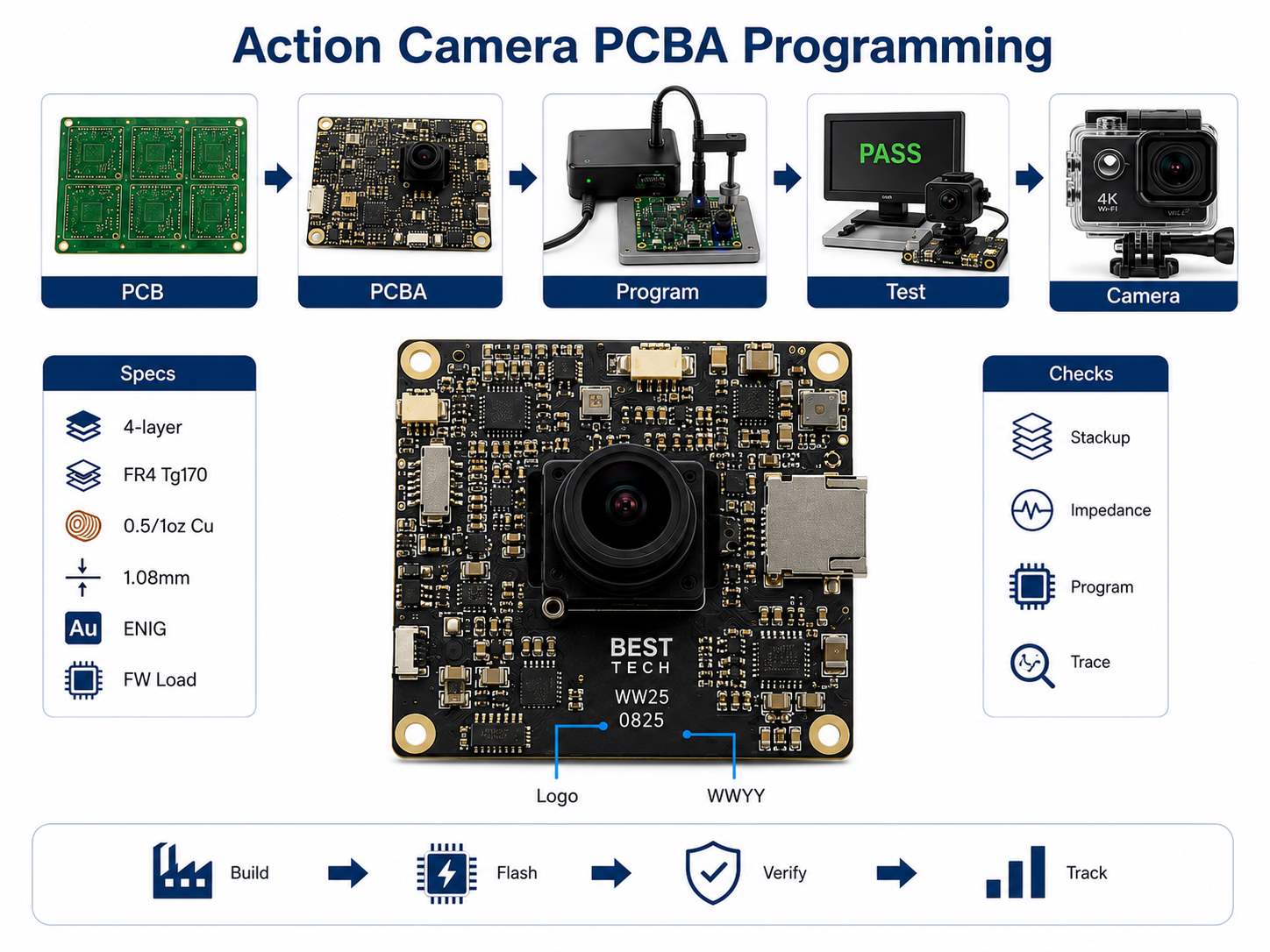
PCB Programming Case Study for an Action Camera PCBA

A European customer needed PCB and PCBA support for an action camera project. The customer had already prepared the camera firmware and product requirements. EBest Circuit’s role was to manufacture the PCB, support assembly, load the customer-provided software, and help verify the board according to the approved test instructions.

Project requirements

  • FR4 4 layer PCB
  • FR4 Tg170
  • Inner copper: 0.5oz
  • Outer finished copper: 1oz
  • Board thickness: 1.08mm ±10%
  • Green solder mask, white silkscreen
  • ENIG, Au 1u”
  • Controlled impedance requirement
  • EBest Circuit logo on board
  • Production date code in WWYY format
  • Suggested panel size: 128.75mm × 77.148mm / 5 pcs
  • Customer-provided firmware for action camera PCBA programming

Why this project needed careful control

The first checkpoint was the PCB structure. An action camera board usually has compact component placement, camera-related signal paths, power circuits, storage interface, connectors, and sometimes high-speed or impedance-sensitive lines. The 4-layer stackup, copper thickness, board thickness, and impedance requirement needed to be reviewed before production.

The second checkpoint was programming preparation. The customer needed the correct software loaded after assembly. That meant the firmware version, programming method, programming interface, and post-programming test steps had to be clear before production started.

The third checkpoint was production traceability. The customer required the EBest Circuit logo and WWYY production cycle marking, which helped identify the production batch. For programmed PCBA products, this is useful because the PCB batch, assembly batch, and firmware version should not become disconnected.

EBest Circuit’s support

  • Reviewed Gerber, BOM, stackup, impedance notes, and panel information
  • Confirmed FR4 Tg170, copper thickness, ENIG, solder mask, silkscreen, logo, and date code
  • Supported PCB fabrication and PCBA assembly in one workflow
  • Loaded customer-provided firmware according to customer instructions
  • Coordinated functional testing after programming
  • Checked programming result, assembly quality, and board cleanliness
  • Supported batch traceability for production control

For the customer, the value was not software development. The value was production execution. EBest Circuit helped connect PCB fabrication, PCBA assembly, customer-provided firmware flashing, functional testing, and batch marking in one controlled process. This reduced the risk of wrong firmware version, unclear test steps, or production handoff mistakes.

how to program a pcb

Why Choose EBest Circuit for PCB Programming Support in PCBA?

EBest Circuit is suitable for customers who need PCB manufacturing, PCBA assembly, and production programming support based on customer-approved firmware files.

Customers choose EBest Circuit because we can support:

  • PCB fabrication
  • Component sourcing based on approved BOM
  • SMT assembly
  • Connector assembly
  • DFM review before production
  • IC or MCU programming based on customer files
  • Functional testing coordination
  • Prototype and small-batch production
  • Batch marking and production traceability
  • One-stop PCB + sourcing + assembly service

For PCB programming projects, EBest Circuit focuses on production reliability. We help confirm files, interfaces, version requirements, test methods, and packing notes before production starts.
If you have a PCBA project that needs programming support, feel free to contact us with your Gerber files, ODB++ files, BOM, firmware file, programming instructions, test method, or assembly notes via sales@bestpcbs.com. We are here to help review the PCB and PCBA manufacturing path before production. 

PCB Programming FAQs

1. Can a PCB be programmed directly?

No. A bare PCB cannot be programmed directly. The programmable parts on the PCB, such as MCU, IC, EEPROM, FPGA, or module, are programmed after assembly.

2. What do I need to program a PCB board?

You need the assembled PCB, firmware file, programming interface, programming tool, power supply method, and a clear test procedure.

3. Can a Gerber file be used to program a PCB?

No. A Gerber file is for PCB fabrication. Programming requires a firmware file or software file plus a programming method.

4. Can EBest Circuit write firmware for my PCB?

EBest Circuit mainly supports PCB manufacturing, component sourcing, PCBA assembly, firmware flashing based on customer-provided files, inspection, and testing coordination. Firmware development should be handled by the customer’s software team.

5. Can PCB programming be done during mass production?

Yes. PCB programming can be done during PCBA production if the programming interface, firmware file, test method, and version control process are confirmed before production.

Need help with PCB programming during PCBA production? Please do not hesitate to contact us with your Gerber files, BOM, firmware file, programming instructions, test method, or assembly requirements via sales@bestpcbs.com. EBest Circuit is committed to helping review the manufacturing, assembly, programming, and testing path before production starts.
You may also like