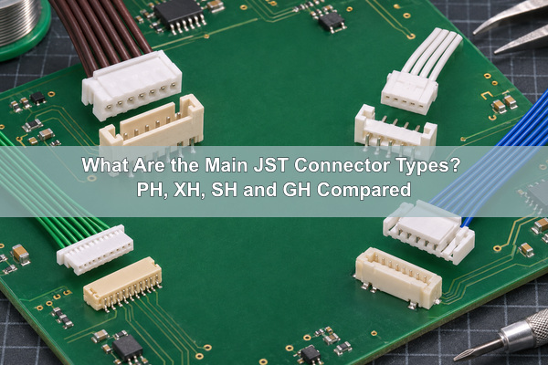
JST connector types are identified by series, pitch, board header, mating direction and wire-side housing. For the four common wire-to-board families covered here, PH uses a 2.0 mm pitch, XH uses 2.5 mm, SH uses 1.0 mm and GH uses 1.25 mm. The same pin count does not make two series interchangeable. The housing, crimp contact, PCB footprint and header must belong to a compatible series.
What Are JST Connectors?
JST is the name of J.S.T. Mfg. Co., Ltd., which produces many connector series rather than one universal plug. In a wire-to-board connection, the complete interface normally includes a PCB header, a wire housing, crimp contacts and terminated wires. Each family has its own pitch, polarization features, locking method, current and voltage ratings, wire range and board footprint.
In PCB and PCBA work, “JST connector” is therefore incomplete BOM information. We need the manufacturer part number for the board header and the mating housing, plus the contact, wire and orientation requirements. A visually similar clone or a housing with the same circuit count may still have a different pitch or keying feature.
How Can You Identify JST Connector Types?
Start with pitch, measured from the center of one contact to the center of the next. Then inspect whether the PCB part is through-hole or surface mount, whether the cable enters from the top or side, and whether the housing uses a friction lock or a positive latch. Finally, verify the molded housing code or the complete part number against the current manufacturer drawing.
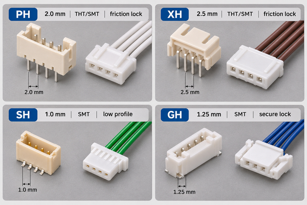
| Series | Pitch | Board-side mounting | Mating wire housing | Fast visual clue |
|---|---|---|---|---|
| PH | 2.0 mm | Through-hole or SMT; top-entry or side-entry versions | PHR-n housing with the specified PH crimp contact | Compact friction-lock housing, smaller than XH but larger than SH/GH |
| XH | 2.5 mm | Through-hole or SMT; top-entry or side-entry versions | XHP-n housing with the specified XH crimp contact | Largest of these four families; taller box-shaped shroud |
| SH | 1.0 mm | SMT; top-entry or side-entry versions | SHR-nV-S-B or SHR-nV-S housing, depending on housing style | Very small, low-profile friction-lock connector for fine wires |
| GH | 1.25 mm | SMT; top-entry or side-entry versions | GHR-nV-S housing with the specified GH contact | Small connector with a distinct secure-lock feature |
The table is an identification aid, not a substitute for the drawing. Measure pitch at the contact centers rather than across the outer housing. If a 4-position connector measures approximately 7.5 mm from the first to the fourth contact, the pitch is about 2.5 mm; the same four positions at 2.0 mm pitch span about 6.0 mm.
What If the Connector Does Not Match PH, XH, SH or GH?
Do not force the part into one of these four families. Photograph the mating face and side profile beside a scale, record the circuit count, measure the center-to-center pitch, and note the board mounting, cable-entry direction, latch and any molded code. Use those observations to search the JST product selector and compare the complete drawing, including housing width, keying and contact geometry. If no drawing matches, continue with other JST series and other connector manufacturers; the part should remain unidentified in the BOM until its manufacturer and complete part number are confirmed.
What Is a JST PH Connector?
The JST PH series is a 2.0 mm-pitch wire-to-board family available with through-hole and SMT headers in top-entry and side-entry configurations. Its practical identification clues are the compact friction-lock housing and the smaller outline compared with XH. Selection still depends on the PH wire range, electrical rating, mating height and exact board footprint.
A typical 4-circuit wire housing is PHR-4. A top-entry through-hole header can use the B4B-PH-K-S family, while a side-entry through-hole header uses the corresponding S4B-PH-K-S family. The exact suffix, plating, color, packaging and current revision still need to match the approved BOM and drawing.
What Is a JST XH Connector?
The JST XH series uses a 2.5 mm pitch and is physically larger and taller than PH, SH and GH. Through-hole and SMT headers are available in top-entry and side-entry forms. The larger housing is a useful visual clue, but the official 2.5 mm pitch and complete part number are more reliable than color or apparent size.
A typical 4-circuit housing is XHP-4. Board header families include B4B-XH-A for top entry and S4B-XH-A for side entry. The familiar white shroud is not enough to identify XH: many generic housings resemble it, and some listings incorrectly call 2.54 mm products “XH” even though the official series pitch is 2.5 mm.
What Is a JST SH Connector?
The JST SH series is the smallest-pitch family in this comparison. It uses low-profile SMT headers in top-entry and side-entry forms. Fine contacts, the shallow housing and the absence of through-hole header options distinguish it from PH and XH; magnified inspection is more reliable than judging it from an unscaled product photograph.
The wire housing may use the SHR-04V-S-B or SHR-04V-S pattern for four circuits, depending on the housing style. Header families include BM04B-SRSS-TB for top entry and SM04B-SRSS-TB for side entry. These suffixes are part of the released selection and should not be shortened to “SH 4-pin.”
What Is a JST GH Connector?
The JST GH series uses SMT board headers and is distinguished from SH by its 1.25 mm pitch and secure-lock design. The positive latch is the most useful visual clue in this four-family comparison, especially when vibration or handling could separate a friction-lock housing.
A typical 4-circuit housing is GHR-04V-S. Board header families include BM04B-GHS-TBT for top entry and SM04B-GHS-TB for side entry. GH is useful when a compact connector also needs positive locking, but the correct choice still depends on the mating-cycle, wire, current, voltage, temperature and mechanical requirements in the approved design.
JST PH vs XH: What Is the Difference?
The main JST PH vs XH difference is pitch: PH is 2.0 mm and XH is 2.5 mm. XH is larger and has higher listed current and voltage ratings under the manufacturer’s stated wire conditions. Their housings, contacts and PCB footprints are different, so a PH housing does not mate with an XH header.
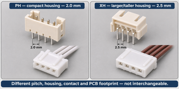
| Comparison | JST PH | JST XH |
|---|---|---|
| Pitch | 2.0 mm | 2.5 mm |
| Typical size | More compact | Larger and taller |
| Board mounting | Through-hole and SMT | Through-hole and SMT |
| Mating direction | Top or side entry | Top or side entry |
| Official listed current condition | 2 A AC/DC with AWG 24 | 3 A AC/DC with AWG 22 |
| Official listed voltage | 100 V AC/DC | 250 V AC/DC |
| Housing pattern | PHR-n | XHP-n |
| Interchangeable? | No. Pitch, housing, contact and footprint differ. | |
Choose between PH and XH from the electrical and mechanical requirements, not from the belief that the larger series is automatically better. PH can reduce occupied area; XH can support a different wire range and higher listed ratings. Board height, cable exit direction, service access and harness availability may decide the choice before current rating does.
Detailed JST PH, XH, SH and GH Connector Parameters
For these JST connector types, the following values come from the current JST series pages referenced above. Rated current depends on the stated wire size, and temperature limits can vary by product configuration or document revision. Use the complete manufacturer part number and current drawing for final design release.
| Parameter | PH | XH | SH | GH |
|---|---|---|---|---|
| Pitch | 2.0 mm | 2.5 mm | 1.0 mm | 1.25 mm |
| Board mounting | Through-hole, SMT | Through-hole, SMT | SMT | SMT |
| Mating direction | Top, side | Top, side | Top, side | Top, side |
| Lock type | Friction lock | Friction lock | Friction lock | Secure lock |
| Circuits listed by JST | 2–16 | 1–16 and 20 | 2–16 and 20 | 2–15 |
| Rated current condition | 2 A with AWG 24 | 3 A with AWG 22 | 1 A with AWG 28 | 1 A with AWG 26 |
| Rated voltage | 100 V AC/DC | 250 V AC/DC | 50 V AC/DC | 50 V AC/DC |
| Conductor range listed by JST | AWG 32–24 | AWG 30–22 | AWG 32–28 | AWG 30–26 |
| Typical wire housing family | PHR-n | XHP-n | SHR-nV-S-B / SHR-nV-S | GHR-nV-S |
How Do You Match the Header, Housing and Crimp Terminal?
Match by series first, then circuit count, entry direction, board mounting and part-number suffix. The housing and header need the same series and number of circuits. The crimp contact must fit both the housing and the specified conductor and insulation diameter. Gold- or tin-plated options, packaging and color suffixes also need to follow the approved BOM.
| Item to match | What to verify | Typical error |
|---|---|---|
| Series | PH, XH, SH or GH on every mating component | Pairing a visually similar housing with the wrong header |
| Circuit count | Same number of positions on housing and header | Ordering a 3-position housing for a 4-position board header |
| Crimp contact | Approved contact family, plating, wire gauge and insulation diameter | Using a contact that fits the housing but not the wire |
| Entry direction | Top entry or side entry relative to the PCB | Cable collides with the enclosure or blocks service access |
| Mounting method | Through-hole or SMT footprint and process | Using an SMT footprint for a through-hole header |
| Suffix and revision | Plating, color, packaging, boss or retention option | Shortening the BOM to a family name and losing a required option |
A complete example shows how these checks work together. For a four-circuit, top-entry, through-hole PH interface, the JST PH connector document supports the following combination. It is an example of a compatible selection path, not a substitute for checking the revision and suffix required by the released product.
| Selection item | Four-circuit PH example | Why it matches |
|---|---|---|
| PCB header | B4B-PH-K-S | PH series, four circuits, top-entry, through-hole board header |
| Wire housing | PHR-4 | PH series receptacle housing with four positions |
| Crimp contact | SPH-002T-P0.5S | Standard PH crimp contact listed for the applicable conductor and insulation range |
| Conductor range | AWG 30–24; 0.05–0.22 mm² | The selected wire conductor must fall within the contact range |
| Insulation outside diameter | 0.8–1.5 mm | The insulation crimp must fit the actual cable, not only the conductor gauge |
| JST tooling reference | AP-K2N machine, MKS-L applicator, APLMK SPH002-05S applicator with dies | The terminal and tooling combination controls the specified crimp geometry |
The selection is not complete until the actual wire is checked against both limits. An AWG 26 conductor with 1.7 mm insulation, for example, satisfies the conductor range but exceeds the listed insulation outside diameter for this contact. It therefore cannot be approved from wire gauge alone. The production release should also confirm the required plating, header suffix, strip length, crimp height and pull-force criteria from the applicable drawing and crimp specification.
How Does Entry Direction Affect PCB Layout?
A top-entry header places the wire housing above the board, while a side-entry header routes the cable parallel to the board. Top entry may simplify access but needs vertical clearance. Side entry can reduce assembly height, yet it needs edge clearance, cable bend space and a path that avoids tall components, sharp edges and moving parts.
The PCB footprint must come from the selected header drawing, not from pitch alone. Pad dimensions, drill size, locating bosses, hold-down tabs, courtyard and connector origin all affect assembly. For a through-hole header, the plated-hole and annular-ring design must match the lead and soldering process. For SH and GH SMT headers, pad geometry and paste control are important because the contacts and retention tabs are small.
For a rigid FR4 PCB, we check the selected header drawing against the released pad, plated-hole, solder-mask and mechanical-clearance data. This connector-specific footprint review is what prevents a correct housing family from being paired with the wrong drill or land pattern.
What Should the BOM Specify for JST Connectors?
A production BOM should identify the exact board header, not only “JST 4 pin.” The harness drawing or cable BOM should identify the wire housing, crimp contact, wire gauge, color, length, strip length and pin-to-pin assignment. If an approved alternate is allowed, it needs its own manufacturer part number and a documented compatibility review.
During PCBA release, complete connector information lets us verify footprint, placement orientation, supply format and mating harness before production. Our custom wire harness service can combine the approved housing, terminals and wire map with the board assembly, while the customer retains control of the released connector and pinout requirements.
| Controlled field | PCB BOM or drawing | Harness drawing |
|---|---|---|
| Series and part number | Complete header manufacturer part number | Complete housing and contact part numbers |
| Position count | Header circuit count | Housing circuit count and any empty positions |
| Orientation | Top/side entry, pin 1, rotation and board side | Pin 1, wire exit and mating view |
| Electrical assignment | Net names and connector reference designator | From-to wire map and pinout |
| Wire definition | Interface current and voltage requirements | Gauge, insulation, color, length and termination |
| Approved sourcing | AVL, packaging and alternates | Approved housing/contact/wire sources and substitution rules |
How Do We Assemble JST Connectors on a PCBA?
We begin with BOM and footprint verification, then check the first article against the assembly drawing and mating direction. Through-hole PH or XH headers may be wave-, selective- or hand-soldered according to the board and process plan. SMT PH, XH, SH and GH headers require controlled paste printing, placement and reflow. For their fine terminals and retention tabs, the SMT stencil aperture and thickness are reviewed with the pad geometry, paste volume and nearby component clearance.
Our PCB assembly service supports SMT, through-hole and mixed assembly. Connector packaging also matters: tape-and-reel SMT headers suit automatic placement, while tray, tube or loose packaging can change feeding and labor. We confirm the actual package and quantity before selecting the assembly route.
How Do We Inspect JST Connector Assembly?
Inspection checks both identity and workmanship. We verify the manufacturer part number, circuit count, entry direction, pin-1 orientation and seating against the BOM and assembly drawing. AOI can evaluate visible SMT leads and retention tabs; magnified visual inspection checks through-hole solder fill and exposed joints. Hidden mechanical or electrical problems still require mating and continuity checks.
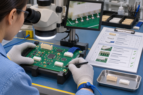
| Inspection stage | Check | Evidence retained when specified |
|---|---|---|
| Incoming | Part number, label, quantity, packaging, appearance and approved source | Receiving record and lot/date-code reference |
| First article | Series, position count, footprint, entry direction, pin 1 and enclosure clearance | First-article checklist and approved image |
| SMT inspection | Lead wetting, bridges, opens, position and retention-tab joints | AOI result and image reference where required |
| Through-hole inspection | Solder fill, wetting, lead protrusion and connector seating | Visual inspection result |
| Mating check | Correct housing fit, latch engagement, insertion and removal | Sample or lot check result |
| Electrical check | Continuity, pinout and harness-to-board mapping | Test result linked to the work order or serial/lot |
This sequence creates a traceable path from approved part number to assembled interface: the BOM defines the header, the harness file defines the mating parts and pinout, the first article confirms the physical match, and inspection records show the checks completed for production.
JST Connector Types FAQs
Are JST PH and XH interchangeable?
No. PH has a 2.0 mm pitch and XH has a 2.5 mm pitch. Their housings, contacts and PCB headers are different.
How do I identify an unknown JST connector?
Count the positions, measure center-to-center pitch, identify through-hole or SMT mounting, note top or side entry, inspect the locking feature and search the molded code or board-header part number in the current manufacturer drawing. If PH, XH, SH and GH do not match, search other JST series with the same measured features and compare the dimensional drawing. If no JST drawing matches, check other manufacturers rather than assigning a JST family from appearance alone.
Is every white 2-pin connector a JST connector?
No. Housing color and pin count are not reliable identification methods. Many manufacturers make visually similar connector families, and some marketplace listings use “JST” as a generic label.
Which is smaller, JST SH or GH?
SH has the smaller pitch at 1.0 mm. GH uses 1.25 mm and adds a secure-lock design. Size alone does not decide suitability; confirm wire, electrical and mechanical requirements.
What files should I send for a PCBA with JST connectors?
Send the Gerber and fabrication files, BOM with complete manufacturer part numbers, placement data, assembly drawing, connector orientation and pin-1 marks, plus the harness drawing or mating-part list. Include approved alternates, inspection requirements and any mating or continuity test that must be quoted. At EBest Circuit (Best Technology), we can review PCB fabrication, component sourcing, assembly and harness requirements as one controlled package. Send the controlled files to sales@bestpcbs.com.