Measure the current step at the board before trusting the voltage dip. Then measure voltage at the regulator output capacitor and at the load, each against its local return. If the regulator node holds but the load node falls, start with the delivery path and local decoupling. If both nodes fall together, also check the converter and its input supply. A clean trace taken with a slower-than-required current step is not a pass.
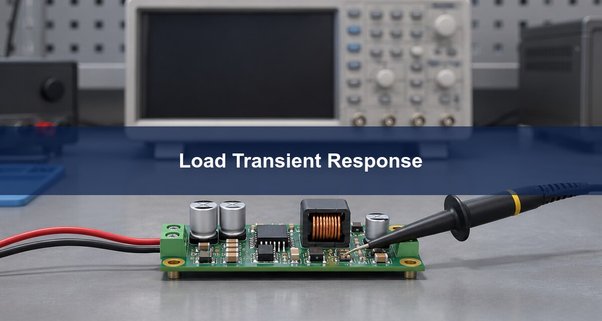
Load Transient Response: What the Test Proves
A load transient test shows how far a supply voltage moves and how quickly it recovers after a defined change in current. It is not steady-state load regulation, switching ripple, or a change in input voltage. Write the start and end currents, rising and falling edge rates, dwell times, input condition, temperature and voltage measurement points into the test plan. For a processor rail, test the transition into the active state and the return to idle; one can cause droop while the other causes overshoot.
Load Transient Test: Electronic Load vs. Local Pulser
Use a programmable electronic load when it can reproduce the current measured at the board. For a fast, low-voltage edge, long wiring and load headroom can prevent the instrument from delivering what its controls indicate. A verified local pulser shortens that loop, but it needs its own measurement, pulse rating and thermal review. The Texas Instruments comparison of transient load options describes both approaches.
| Setup | Choose when | Verify before use |
| Bench electronic load | You need repeatable current levels and can meet the edge at the PCB. | Measured slew, compliance and lead inductance. |
| Local pulse load | The bench leads slow or distort the required edge. | Current waveform, pulse dissipation and the local return path. |
| Actual IC workload | You need to catch behavior missed by a simple two-level step. | Reproducible operating state and a way to correlate the waveform. |
Current Slew Rate: Verify the Edge Instead of Assuming It
Read change in current divided by elapsed time on the actual current trace. If a hypothetical setup rises from 1 A to 5 A in 2 µs over the full measured transition, the average is 2 A/µs. If the protocol uses 10% to 90% thresholds, use that interval and the corresponding current change, not the full 4 A numerator. Check the falling edge independently, and record where the current is sensed so a fixture branch is not mistaken for total regulator output current.
When using a sense resistor, confirm its value and measurement bandwidth. The TI transient-load example computes current from the measured sense voltage and resistance. A shunt that adds appreciable inductance or voltage drop can change the very edge it is intended to capture.
How to Measure Load Transient Response at Two Nodes
Capture regulator output voltage across its output capacitor and load voltage across the load’s local power and return. Use a short connection and suitable differential or low-loop-area probe arrangement. Verify instrument grounding before attaching probes; do not tie separate return nodes together through grounded clips. Use a shared time base and trigger on the measured current edge. Use DC coupling for absolute rail limits and record the bandwidth when comparing peaks. Analog Devices’ fast-load measurement example locates the regulator-side measurement across the output capacitor.
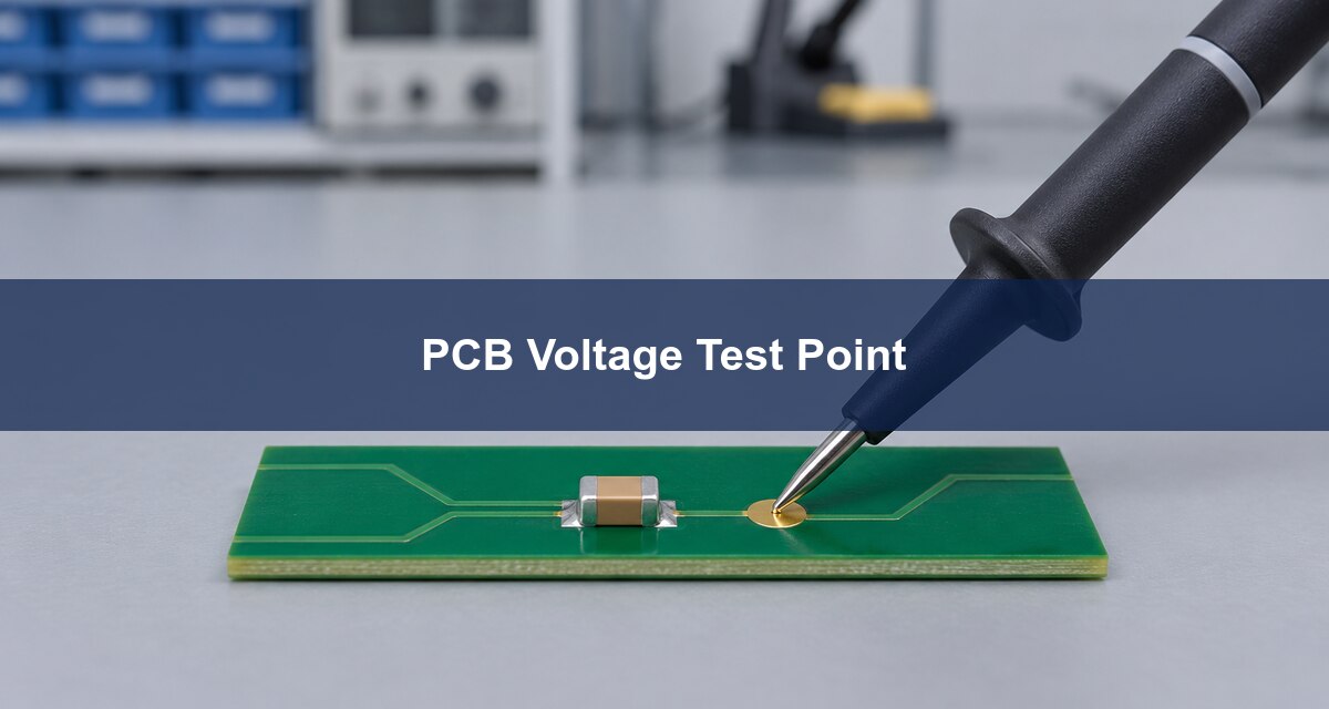
Voltage Droop: Separate a Sharp Edge From a Deeper Sag
A sharp excursion that grows with edge rate suggests checking the current loop and the measurement first. A simple estimate is voltage = inductance × current slew rate. An assumed 10 nH path carrying a 2 A/µs current change produces a 20 mV inductive term; that is not a prediction of total rail droop. If a drop persists while the higher current is steady, compare the two local voltages and check the resistive path. If the regulator output itself sags, examine the output capacitor’s effective value at bias, the input supply and the regulator response.
Buck Converter Load Transient Response: Diagnose Before Replacing Parts
Change one condition at a time when a waveform fails. Reducing the input lead length, moving an output probe, or repeating the step with a verified local pulser can distinguish faults that look similar on a single trace. Changing compensation or adding capacitors before the stimulus is verified can hide a fixture problem or create a different stability issue.
| What you see | First check | What would change the diagnosis |
| Current edge is slow or clips. | Load headroom, lead loop and measured current. | A verified local load restores the intended edge. |
| Only the load node drops sharply. | Local return, path inductance and point-of-load capacitance. | The excursion scales with edge rate and survives a probe repeat. |
| Input and both rail nodes sag. | Upstream source and input network. | A stiffer input improves the rail at the same measured step. |
| Both output nodes ring after a clean step. | Probe repeatability and regulator loop behavior. | Ringing persists across sound setups; perform separate stability checks. |
Power Supply Transient Response: Define a Reproducible Pass
Agree the absolute voltage limits and the recovery band before testing. Record timing from the actual current transition and define how long the voltage must remain in the recovery band before calling it settled. For an illustrative 1.00 V rail with an agreed 0.95 V minimum at the load, 0.97 V at the regulator and 0.94 V at the load do not pass. Confirm the current and probing first; then investigate the extra 30 mV between those two measurements at the same instant. Run the required voltage, temperature and loading corners instead of certifying the production rail from a single room-temperature waveform.
FAQ
Can I trust the current edge shown on an electronic load’s display?
Use a board-side measurement for a fast step. A front-panel setting does not prove what current reached the PCB through the wiring.
Should I measure at the regulator or the load?
Measure both when the load’s limit is what matters. The regulator node helps identify whether the delivery path adds an excursion.
Does a clean load transient prove stability at all conditions?
No. It is evidence for the tested conditions. Separate stability measurements and corner tests may still be needed.
Can I use the scope’s bandwidth limit to hide a spike?
Use the bandwidth defined by the test plan. Do not discard a visible event unless you have checked whether it originates in the probe or the circuit.
Why test load release as well as load application?
The converter responds differently when the current demand falls. A rail can pass the droop limit and fail the overshoot limit.
Will adding bulk capacitance always fix a short spike?
No. If the excursion is caused by path inductance or long probe leads, additional bulk capacitance may not address it.
Can I reuse a regulator datasheet waveform as a pass limit?
Use it as a reference only when its conditions are relevant. Your load’s voltage envelope and actual board determine acceptance.
What should I save for a repeat test?
Save synchronized current and voltage traces, the node and ground locations, fixture geometry, hardware revision, temperature, input condition and scope settings.
Review the Power Rail Before the Next PCB Spin
For the broader production test plan, see the DC-DC converter testing guide. For a Best Technology PCB fabrication discussion, send the stackup, supply and return layout, rail limits and test-point drawing to sales@bestpcbs.com. Include the measured current step and both voltage traces so the discussion can focus on the relevant part of the board.