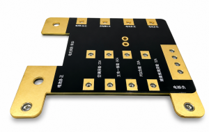
Isola IS550H is a halogen-free, high-reliability laminate and prepreg system for high-power, high-voltage and automotive electrification PCBs. Its published properties include a 200°C glass transition temperature, 400°C decomposition temperature, low total Z-axis expansion and resistance to conductive anodic filament growth. These attributes make the material relevant when long-term thermal and insulation reliability matter more than ultra-low dielectric loss.
IS550H is not a universal upgrade for every circuit board. Its Df reaches 0.016 at 10 GHz, so it should not be treated as a dedicated low-loss material for millimeter-wave RF or demanding high-speed serial channels. The correct decision connects the datasheet values to the operating voltage, thermal cycle, copper construction, stack-up, manufacturing process and finished-board qualification plan.
What Is IS550H PCB Material?
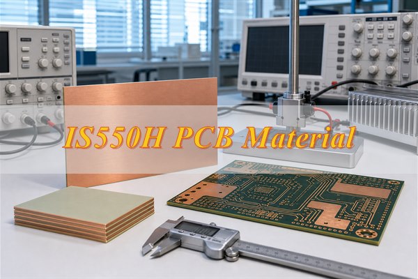
IS550H PCB material is a high-reliability, halogen-free epoxy laminate and prepreg developed by Isola for harsh high-voltage and high-power environments. It belongs to the high-reliability epoxy category rather than PTFE or Isola’s low-loss I-Tera family. The material is supplied as copper-clad laminate and prepreg for multilayer PCB fabrication.
The current product sheet identifies IS550H under IPC-4101/140 and UL file E41625. It is listed as RoHS compliant, UL 94 V-0, compatible with lead-free assembly, and capable of six 260°C reflow cycles and six 288°C solder-float exposures under the supplier’s stated test conditions. These material-level results help screen a laminate, but they do not guarantee that every finished PCB will survive the same exposure.
A laminate system has two related forms. The cured copper-clad core provides stable dielectric layers, while uncured prepreg bonds cores and copper foils during multilayer lamination. IS550H prepreg selection therefore affects pressed thickness, resin flow and the ability to fill spaces around heavy copper. Requesting “IS550H” without freezing the core, prepreg and copper construction leaves important production variables open.
- Material identity: State “Isola IS550H laminate and prepreg” on the fabrication drawing instead of using only a generic halogen-free FR-4 callout.
- Primary purpose: Select the material for thermal reliability, high-voltage insulation and CAF resistance rather than for the lowest possible insertion loss.
- Construction control: Record approved core thicknesses, prepreg glass styles, resin content, copper foil and substitution restrictions.
- Qualification boundary: Convert the application requirements into finished-board tests because laminate data alone cannot validate the entire PCB.
What Does the IS550H Datasheet Reveal?
The IS550H datasheet describes a thermally stable epoxy system with strong insulation properties and moderate dielectric loss. Tg, Td and Z-axis expansion indicate how the resin responds to heat; Dk and Df influence transmission-line behavior; thermal conductivity affects the dielectric portion of the heat path; and moisture, insulation and CAF-related properties help assess high-voltage risk.
| Property | Typical Value |
| Glass transition temperature, DSC | 200°C |
| Decomposition temperature, 5% weight loss | 400°C |
| T260 / T288 | >60 minutes |
| Z-axis CTE, pre-Tg / post-Tg | 38 / 210 ppm/°C |
| Total Z-axis expansion, 50–260°C | 2.2% |
| Thermal conductivity | 0.7 W/m·K |
| Dk at 2 / 5 / 10 GHz | 4.50 / 4.43 / 4.43 |
| Df at 2 / 5 / 10 GHz | 0.014 / 0.014 / 0.016 |
| Electric strength | 46.9 kV/mm |
| Moisture absorption | 0.25% |
| Relative thermal index | 150°C |
| Flammability | UL 94 V-0 |
Why Does IS550H Perform Well in High-Voltage Environments?
IS550H addresses four material-level risks found in high-voltage PCBs.
- CAF resistance: The resin system helps resist conductive filament growth along glass-resin interfaces under voltage and humidity.
- Moisture control: A typical absorption value of 0.25% supports insulation stability in humid service.
- Thermal stability: A 200°C Tg, 400°C Td and 2.2% total Z-axis expansion reduce material movement during soldering and thermal cycling.
- Electrical insulation: The published electric-strength data supports material screening for high-voltage constructions.
These properties do not permit reduced creepage or clearance. Set spacing from working voltage, transients, pollution degree, altitude, coating and the applicable product-safety standard. Validate finished boards with appropriate insulation-resistance, hi-pot, cleanliness or CAF tests.
Where Is IS550H Commonly Used?
IS550H is most useful in high-voltage power electronics that combine electrical stress, repeated thermal cycling and long service expectations. The application decision should be driven by the real failure risks, not by the industry label alone. An automotive board with modest voltage and temperature may not require IS550H, while an industrial converter with severe bias and humidity may benefit from it.
- Automotive electrification: On-board chargers, traction inverter controls, DC-DC converters, battery-management electronics and high-voltage distribution assemblies.
- Energy systems: Energy-storage converters, charging equipment, power-control boards and renewable-energy power electronics.
- Industrial power: Motor drives, high-voltage supplies, industrial converters and controls exposed to thermal or electrical stress.
- Heavy-copper boards: Multilayers that require significant resin fill around thick conductors and stable plated holes through thermal cycling.
- High-reliability equipment: Medical, transportation or aerospace power electronics where the selected construction is qualified to the applicable project requirements.
For an IS550H automotive PCB, the qualification profile should represent the actual assembly. Define the low and high temperatures, ramp rate, dwell time, cycle count, applied voltage, humidity condition and acceptance criteria. A material promoted for automotive electrification does not automatically satisfy an OEM specification or a functional-safety requirement.
When Should IS550H Not Be Used?
Do not select IS550H when another material matches the dominant requirement more directly.
- Low-loss RF or long high-speed channels: Its Df is 0.016 at 10 GHz. Model insertion loss, copper roughness, connectors and equalization against a dedicated low-loss laminate.
- Cost-sensitive, moderate-stress boards: A proven high-Tg FR-4 construction may be sufficient when voltage, temperature, spacing and service life are not demanding.
- Unresolved layout or process defects: IS550H cannot compensate for inadequate clearance, contamination, poor plating or an unqualified stack-up.
Approve the material only when its CAF, thermal or high-voltage properties address a documented project risk.
How Does IS550H Compare with 370HRG, Astra MT77 and I-Tera MT40?
IS550H leads this comparison when CAF resistance and long-term high-voltage thermal reliability are the primary requirements.
| Comparison Dimension | IS550H | 370HRG | Astra MT77 | I-Tera MT40 |
| Primary role | High-voltage, high-power reliability | Halogen-free, high-thermal-reliability FR-4 | Low-loss RF and microwave circuits | Low-loss high-speed digital and RF circuits |
| Halogen-free | Yes | Yes | Confirm the specified construction | Confirm the specified construction |
| Typical Tg / Td | 200°C / 400°C | 185°C / 390°C | 200°C / 360°C | 215°C / 360°C |
| Typical Dk / Df | 4.43 / 0.016 at 10 GHz | 4.3 / 0.015 at 10 GHz | 3.00 / 0.0017 | 3.45 / 0.0031 |
| High-voltage / CAF focus | Strong | General-purpose; verify project evidence | Not the primary selection reason | Not the primary selection reason |
| Signal-loss priority | Moderate loss; Df 0.016 at 10 GHz | Not positioned as an ultra-low-loss system | High | High |
| Typical selection case | OBC, inverter, BMS, high-voltage power and heavy-copper multilayers | Halogen-free industrial and automotive multilayers | RF, radar and microwave structures | High-speed serial channels and low-loss RF structures |
| Substitution check | CAF, thermal cycling, resin fill and availability | Thermal class, CAF evidence and qualification cost | Dk/Df method, copper profile, cure and hybrid compatibility | Dk/Df method, insertion loss, copper profile and stack-up |
None is a drop-in substitute. Compare current datasheets, available thicknesses and copper, processing compatibility, qualification evidence and total redesign cost before changing the released material.
What Should Be Considered When Designing an IS550H PCB?
An IS550H PCB design must control insulation, thermal paths, copper distribution, stack-up and verification as one system.
- Material callout: Specify Isola IS550H laminate and prepreg, approved alternates, copper foil and revision control; do not use only a generic halogen-free FR-4 note.
- Stack-up: Freeze finished thickness, dielectric targets, core and prepreg constructions, copper by layer, resin content and pressed-thickness tolerances.
- Creepage and clearance: Calculate spacing from working voltage, transients, insulation class, pollution degree, altitude, coating and the governing product standard.
- Heavy copper: Balance copper across the panel, maintain resin-rich fill around features, account for etch compensation and avoid abrupt copper-density changes.
- Thermal path: Model component interfaces, planes, thermal vias, dielectric thickness, chassis or heatsink connection and maximum local temperature.
- Plated holes: Set drill size, aspect ratio, annular ring and finished hole-wall copper for the expected solder and service-temperature cycles.
- Signal structures: Use construction-specific Dk, copper thickness and roughness for impedance or insertion-loss analysis; catalog Dk alone is insufficient.
- High-voltage layout: Keep contamination-sensitive nodes away from board edges, slots, fasteners and conductive hardware; define coating keep-outs and cleaning access.
- Qualification: Add representative impedance, microsection, thermal-cycle, insulation-resistance, hi-pot or CAF coupons and acceptance criteria where the risk assessment requires them.
Heavy-copper design requires special attention because copper topography consumes resin during lamination. Prepreg selection should reflect glass style, resin content, copper thickness, retained copper area and the required pressed dielectric. Resin-starved zones, voids or uneven thickness can result when a generic prepreg construction is used without a fill calculation.
The 0.7 W/m·K thermal conductivity helps within the dielectric, but it should not be presented as a complete thermal solution. Copper spreading, thermal vias, component attachment, interface materials and external cooling typically have a larger effect on junction temperature. Verify the complete path with thermal simulation or a representative measurement.
How Is an IS550H PCB Fabricated?
An IS550H PCB can use an FR-4-type production flow, but the press, drilling, desmear and heavy-copper controls must be qualified for the released construction. The supplier’s processing guidance is a starting point; the fabricator must adapt it to panel size, press design, copper distribution, prepreg condition and the actual stack-up.
- Receive and identify the material. Confirm the Isola IS550H designation, product revision, lot, shelf life, laminate thickness, prepreg construction and copper foil. Preserve certificates and receiving records so every panel can be traced to the approved material.
- Store laminate and prepreg correctly. Keep prepreg in moisture-barrier packaging under its specified storage conditions. Before release, inspect packaging integrity and remaining shelf life. Material that has exceeded a controlled exposure limit should not enter production without an approved disposition.
- Image and etch the inner layers. Apply validated dimensional and etch compensation for the copper weight and pattern density. Measure critical conductor widths, spacing and registration after etching. Heavy copper requires additional allowance because lateral etching changes the conductor profile.
- Prepare the bonding surfaces. Clean the inner layers and apply an approved oxide or oxide-alternative treatment. Verify surface condition and treatment uniformity because contamination or weak copper-resin bonding can appear later as delamination during assembly or thermal cycling.
- Lay up the multilayer construction. Check core orientation, prepreg glass style, resin content, ply count, copper balance and tooling. The lay-up traveler should match the released stack-up, and resin-fill calculations should cover the deepest heavy-copper features.
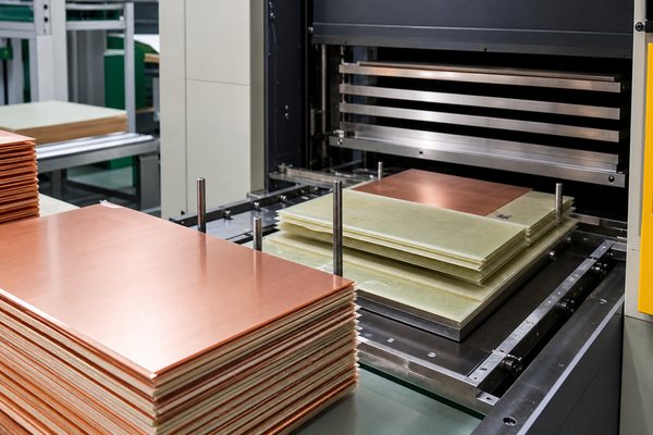
- Laminate with a qualified press cycle. Control heat-up rate, pressure, vacuum, peak cure condition and cooling for the actual panel. Record the press curve, then verify finished thickness, registration and evidence of voiding or resin starvation. A single generic lamination recipe is not suitable for every IS550H construction.
- Drill with controlled tool parameters. Select spindle speed, infeed, retract rate, stack height and tool-hit limit for the hole diameter, copper weight and panel thickness. Inspect representative holes for smear, glass damage, roughness and positional accuracy before metallization.
- Desmear and condition the holes. Use a validated plasma or chemical process to remove resin smear without excessive resin recession or glass-fiber attack. Confirm hole-wall condition through inspection or microsection evidence before electroless copper deposition.
- Plate and form the outer circuits. Establish continuous electroless copper, build the specified electrolytic copper and compensate the outer image for heavy-copper etching. Verify finished hole-wall copper, annular ring, conductor geometry and isolation spacing.
- Finish, clean and release the PCB. Apply solder mask and the specified surface finish, profile the panel without damaging high-voltage slots or edges, and control ionic cleanliness. Complete electrical testing, dimensional inspection and the required coupon or microsection checks before shipment.
Process evidence matters more than a generic statement that the material is “FR-4 compatible.” A useful production record includes material lot, lay-up, press curve, drill tool history, desmear cycle, plating result, microsection and approved deviations. This baseline also makes repeat orders easier to compare and protects the project from an unnoticed material or process change.
How Can EBest Circuit Support an IS550H PCB Project?
EBest Circuit can support an IS550H project by converting the design requirements into a controlled material set, stack-up, fabrication traveler and inspection plan. The most valuable review happens before laminate is ordered, when dielectric thickness, heavy-copper fill, high-voltage spacing and test requirements can still be corrected without disrupting production.
- Material review: Confirm the specified IS550H laminate, prepreg, copper and available construction before the stack-up is frozen.
- DFM review: Check high-voltage spacing, hole structures, copper balance, heavy-copper resin demand, solder-mask registration and test-coupon requirements.
- Process planning: Establish traceable lamination, drilling, desmear, plating and cleanliness controls for prototype and production builds.
- Inspection planning: Align material certificates, microsections, electrical tests, impedance results and high-voltage tests with the customer specification.
- Change control: Preserve the approved baseline and require written authorization before changing the material, prepreg, foil or released stack-up.
For a comparable quotation, provide Gerber or ODB++ files, NC drill data, fabrication drawing, layer stack-up, finished thickness, copper weight by layer, operating voltage and temperature, creepage and clearance requirements, surface finish, quantity and required reports. Include the BOM and assembly test requirements when PCBA service is also requested.
FAQs About IS550H
A1: Not automatically. The laminate is only one material in the finished board. Solder mask, legend ink, adhesives, surface-finish chemistry and assembly materials may require separate declarations. If full-product halogen-free compliance is required, list every controlled material and request documentation for the complete construction. Confirm the requirement in the purchase specification.
A2: Only controlled, in-life prepreg should be reserved. Record the lot, quantity, packaging condition, storage environment, shelf-life limit and project ownership. Before reuse, inspect the package and confirm material status. Reserved stock reduces substitution risk but does not replace incoming inspection or formal material release. Do not combine unidentified remnants with controlled stock.
A3: No; baking depends on moisture history and assembly risk. Review packaging, storage duration, ambient exposure, board thickness, surface finish and the reflow profile. Unnecessary baking can age some finishes, so any required temperature, duration, stacking method and assembly window should be documented. Reseal unused boards promptly after opening for production.
A4: Yes, if the finished plated-hole system is qualified for the connector. Check finished hole diameter, plating thickness, pad geometry, pin specification and insertion force. Representative insertion testing and microsection inspection provide better evidence than relying on the laminate’s mechanical properties alone. Record the approved connector and insertion limits during qualification.
A5: Localized heating can still damage pads, barrels or resin interfaces. Define tip or nozzle temperature, contact time, preheat, fixture support and permitted rework count. Validate large terminals or high-copper areas on a representative assembly because they require more heat than small components. Record the validated thermal profile and apply it consistently.
A6: The solder mask should match the voltage, temperature and compliance requirements of the finished product. Review dielectric performance, adhesion, thermal exposure, minimum dam width and registration around high-voltage features. The laminate designation alone does not determine a suitable solder-mask system. Confirm compatibility with the mask supplier and assembler before volume production.
A7: Only through an approved engineering change. A width adjustment may be necessary after the production stack-up is calculated, but coupled lines, resonant structures and tuned power circuits can be sensitive. Require written approval for every change that affects released electrical geometry. Add the accepted value to the controlled drawing after approval.
A8: Packaging should protect the selected surface finish and the board from moisture, contamination and mechanical damage. Define the bag type, desiccant or humidity indicator when applicable, quantity per pack, sealing method and storage conditions. Finished-PCB storage rules are separate from prepreg shelf-life controls. Label each pack with its lot and date.
A9: Inspect the affected pads, plated holes and nearby laminate interfaces. Check pad adhesion, barrel continuity, lifted lands, solder-mask damage and local discoloration. For high-current or safety-critical connections, use electrical testing or a representative microsection when visual inspection cannot prove the joint’s integrity. Record the rework count and disposition for traceability.
A10: Freeze the approved construction and require written change notification. Retain the laminate revision, core and prepreg details, copper foil, press baseline, drill and desmear controls, inspection coupons and approved deviations. Compare every new production lot with that controlled record before release. This baseline also speeds future deviation reviews and purchasing decisions.
IS550H is a strong candidate when high voltage, heavy copper and severe thermal exposure must be managed in one reliable multilayer PCB. If you need OEM or ODM production, prototype development, volume manufacturing or a custom engineering solution, send your Gerber or ODB++, stack-up, copper requirements, operating conditions, quantity and test plan to sales@bestpcbs.com. The EBest Circuit engineering team can review the construction and prepare a project-specific quotation.