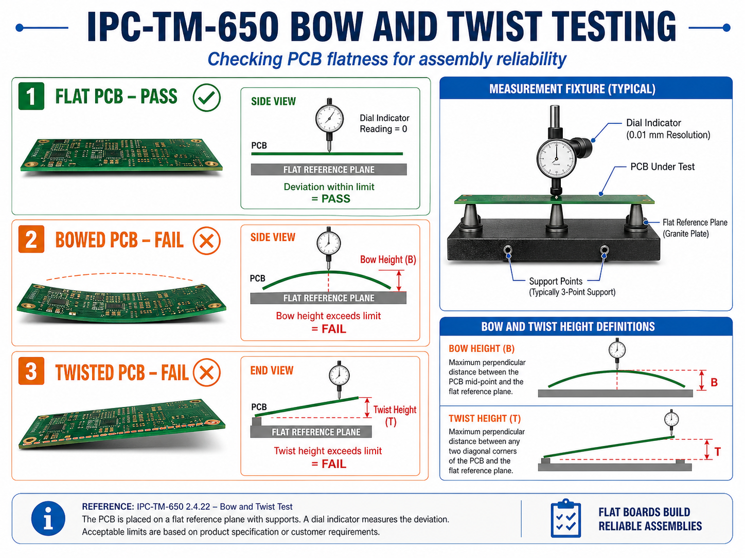
IPC-TM-650 is one of the most important test method references in PCB manufacturing, PCB inspection, and PCBA reliability evaluation. It is not a product certification by itself. It is a collection of standardized test methods used to evaluate printed boards, materials, solder masks, conductors, plated holes, surface cleanliness, insulation resistance, thermal stress, dimensional stability, and environmental durability.
For PCB engineers, IPC-TM-650 helps define how a test should be performed. For buyers, it helps verify whether a PCB supplier has a controlled and repeatable quality process. For manufacturers, it gives a shared technical language when discussing failure analysis, material qualification, process control, and customer acceptance.
What Is IPC-TM-650?
IPC-TM-650 is the IPC Test Methods Manual used for testing printed boards, electronic materials, and related interconnection products. It includes test methods related to reporting and measurement analysis, visual inspection, dimensional measurement, chemical performance, mechanical strength, electrical performance, environmental reliability, and connector evaluation.
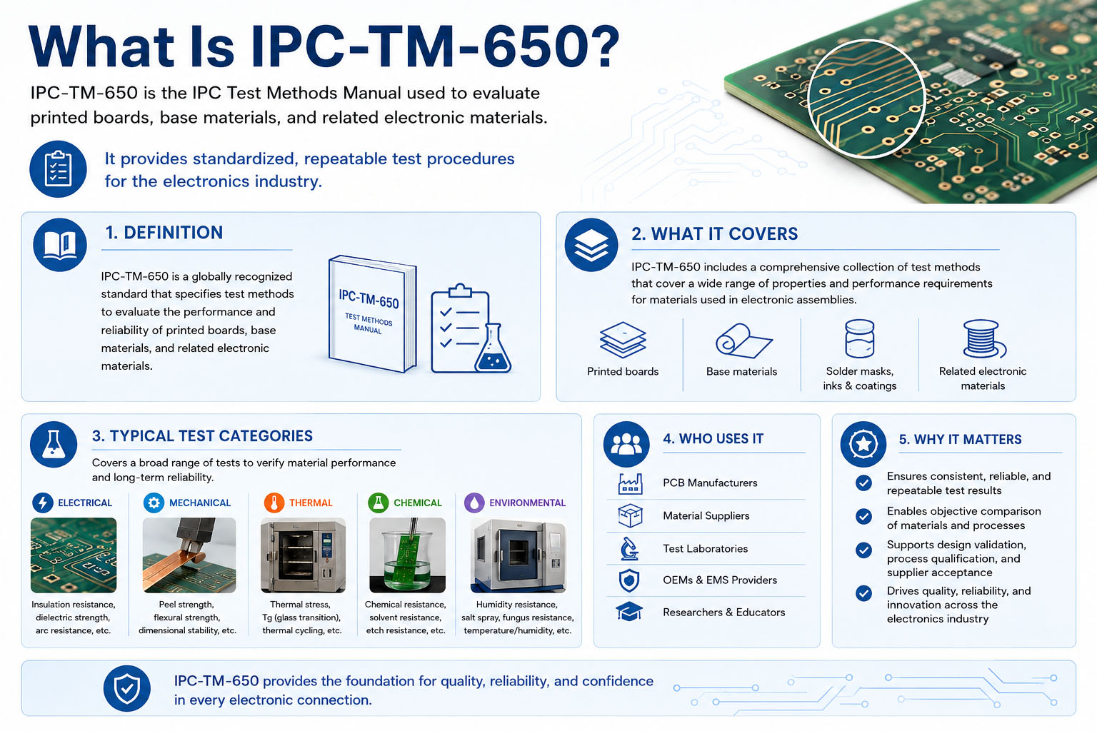
In simple terms, IPC-TM-650 tells engineers how to test a PCB-related property. It does not replace a product performance specification. Instead, it supports standards, drawings, purchase specifications, and customer requirements by defining repeatable test procedures.
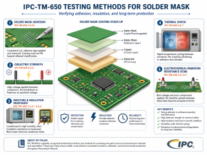
For example, if a customer wants to verify solder mask cure, peel strength, insulation resistance, copper thickness, thermal stress resistance, or dimensional stability, IPC-TM-650 may provide the test method that explains the sample preparation, equipment, test conditions, procedure, and reporting format.
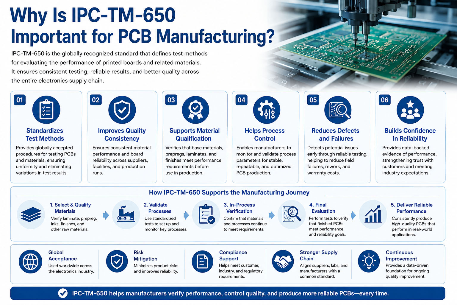
Why Is IPC-TM-650 Important for PCB Manufacturing?
PCB quality cannot be judged only by appearance. A board may look acceptable but still have weak plated-through holes, poor solder mask cure, unstable insulation resistance, ionic contamination, or weak copper adhesion. IPC-TM-650 helps manufacturers and customers evaluate these hidden quality risks through defined test methods.
Its value is especially clear in high-reliability PCB projects, including medical electronics, automotive electronics, aerospace systems, industrial control, telecommunications, robotics, power electronics, and LED thermal management. These products often require more than basic electrical testing.
IPC-TM-650 helps answer practical production questions:
| Production Question | Why IPC-TM-650 Helps |
|---|---|
| Is the solder mask properly cured? | It supports chemical and physical verification. |
| Can plated holes survive thermal stress? | It provides test methods for interconnection reliability. |
| Is the material dimensionally stable? | It supports dimensional stability evaluation. |
| Is insulation resistance acceptable after humidity exposure? | It supports electrical reliability testing. |
| Is copper adhesion strong enough? | It helps evaluate peel strength and conductor bonding. |
| Is the board clean enough after processing? | It supports contamination and cleanliness-related checks. |
For buyers, this means quality becomes measurable rather than subjective. For suppliers, it helps reduce disputes by using recognized test procedures.
How Is IPC-TM-650 Organized?
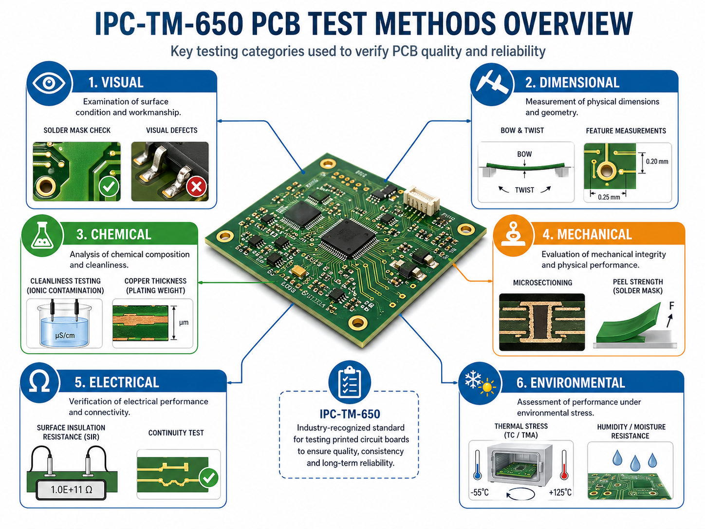
IPC-TM-650 is organized by test method category. Each category focuses on a different type of PCB property or reliability concern. The methods are commonly grouped into visual, dimensional, chemical, mechanical, electrical, environmental, and connector test methods.
| IPC-TM-650 Section | Main Focus | Typical PCB Relevance |
|---|---|---|
| 1.0 Reporting and Measurement Analysis | Calibration, reporting, measurement format | Test consistency and documentation |
| 2.1 Visual Test Methods | Microsectioning, surface examination, hole structure | Internal and external visual evaluation |
| 2.2 Dimensional Test Methods | Hole size, copper thickness, dimensional stability | Board geometry and manufacturing tolerance |
| 2.3 Chemical Test Methods | Solder mask cure, chemical resistance, material properties | Material and surface process reliability |
| 2.4 Mechanical Test Methods | Peel strength, flex endurance, adhesion | Mechanical durability |
| 2.5 Electrical Test Methods | Insulation resistance, dielectric properties, conductor resistance | Electrical performance and insulation quality |
| 2.6 Environmental Test Methods | Thermal shock, temperature cycling, humidity-related testing | Long-term reliability under stress |
| 3.0 Connector Test Methods | Connector-related evaluation | Interconnection and assembly reliability |
This structure is useful because PCB failure can come from many directions. A board may fail mechanically, electrically, chemically, thermally, or dimensionally. IPC-TM-650 gives engineers a method-based way to investigate each risk.
What Tests Are Included in IPC-TM-650?
IPC-TM-650 contains many test methods covering printed boards and related interconnection materials. These test methods support chemical, mechanical, electrical, environmental, visual, and dimensional evaluation for PCB manufacturing and reliability control.
Common test areas include:
- Microsection evaluation
- Plated-through hole structure inspection
- Hole size measurement
- Copper thickness measurement
- Solder mask cure testing
- Chemical resistance testing
- Peel strength testing
- Folding endurance for flexible materials
- Dielectric constant and loss tangent testing
- Insulation resistance testing
- Dielectric withstand voltage testing
- Resistance testing of plated-through holes
- Thermal shock testing
- Temperature cycling
- Environmental insulation resistance testing
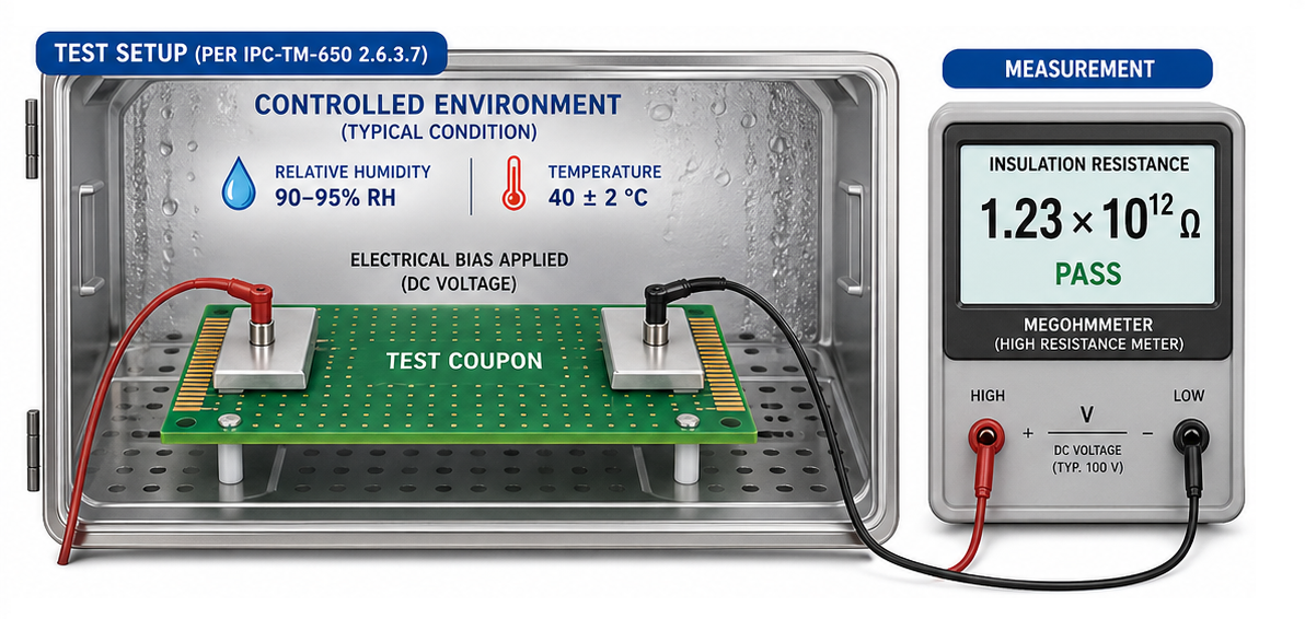
- Surface insulation resistance testing
- CAF-related reliability evaluation
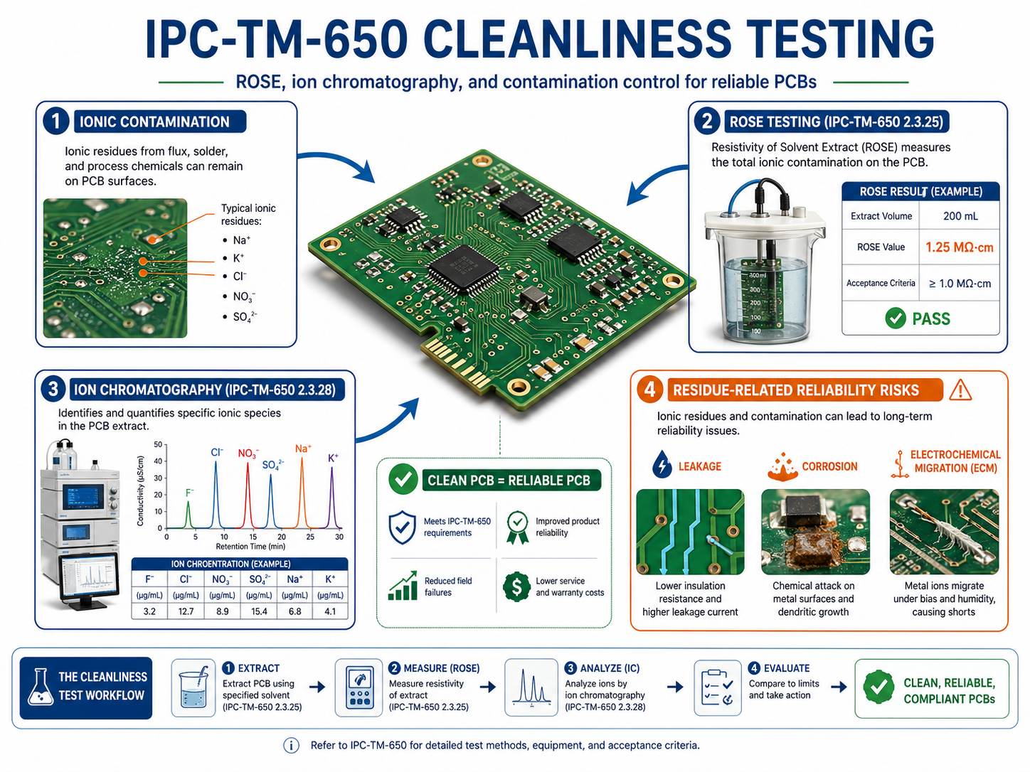
- Cleanliness and contamination-related testing
Not every PCB project needs every IPC-TM-650 test. The correct test plan depends on board type, material, reliability class, customer specification, product environment, and production volume.
How Does IPC-TM-650 Relate to IPC-A-600, IPC-6012, and IPC-J-STD-001?
IPC-TM-650 is often used together with other IPC standards. The relationship is important because many people confuse test methods, workmanship standards, and performance specifications.
| Standard | Main Role | How It Relates to IPC-TM-650 |
|---|---|---|
| IPC-TM-650 | Defines test methods | Explains how to perform specific tests |
| IPC-A-600 | Acceptability of printed boards | Helps visually judge acceptable and nonconforming board conditions |
| IPC-6012 | Performance specification for rigid printed boards | Defines qualification and performance requirements for rigid PCBs |
| IPC-J-STD-001 | Requirements for soldered electrical and electronic assemblies | Defines process and acceptance requirements for soldered assemblies |
| IPC-A-610 | Acceptability of electronic assemblies | Used for PCBA visual inspection and workmanship acceptance |
A simple way to understand the relationship is this:
- IPC-6012 defines what a rigid PCB must meet.
- IPC-A-600 helps inspectors judge what the board looks like.
- IPC-TM-650 explains how to test a property.
- IPC-J-STD-001 focuses on soldered electronic assemblies.
For a serious PCB project, these documents are not competitors. They work together.
Which IPC-TM-650 Tests Matter Most for PCB Fabrication?
The most important IPC-TM-650 methods depend on the board type. A simple two-layer FR4 PCB and a 16-layer HDI PCB do not carry the same risk. A rigid-flex PCB, heavy copper PCB, ceramic PCB, and high-frequency PCB also need different verification points.
For standard rigid PCB fabrication, common focus areas include:
| Test Focus | Why It Matters |
|---|---|
| Microsectioning | Checks hole wall plating, inner-layer connection, voids, cracks, and dielectric condition. |
| Copper thickness | Confirms conductor and hole plating meet requirements. |
| Hole size measurement | Verifies drilling, plating, and finished hole tolerance. |
| Peel strength | Evaluates copper adhesion to the base material. |
| Solder mask cure | Confirms solder mask has reached proper chemical and mechanical stability. |
| Insulation resistance | Checks electrical isolation between conductors. |
| Dielectric withstand voltage | Evaluates insulation under high voltage stress. |
| Thermal stress | Checks plated holes and laminate stability after heat exposure. |
| Dimensional stability | Verifies material movement after processing or thermal exposure. |
For high-density boards, microsection quality becomes especially important because small vias, stacked vias, via-in-pad structures, and fine-pitch layouts leave less process margin.
How Does IPC-TM-650 Help with Material Selection?
Material selection is not only about Tg, dielectric constant, or price. A PCB material must survive fabrication, soldering, operating temperature, humidity, voltage stress, and mechanical loading. IPC-TM-650 gives manufacturers and customers a way to test whether material behavior supports the application.
For example:
- FR4 materials may be checked for thermal stress resistance, dimensional stability, dielectric performance, and insulation resistance.
- High-Tg materials may be selected when boards face lead-free assembly, repeated thermal cycles, or elevated operating temperature.
- Polyimide materials may be evaluated for flexible PCB durability, bending performance, and dimensional behavior.
- High-frequency laminates may require dielectric constant and loss tangent verification.
- Solder mask materials may need cure, adhesion, chemical resistance, and insulation testing.
Material selection should be based on the full application environment. A material that works well for a consumer device may not be suitable for automotive, medical, aerospace, or power electronics. IPC-TM-650 helps turn material choice into a testable decision.
How Does IPC-TM-650 Support PCB Reliability Testing?
Reliability testing is about finding weak points before boards fail in the field. IPC-TM-650 supports this by defining repeatable ways to expose PCB samples to electrical, thermal, mechanical, and environmental stress.
Typical reliability concerns include:
- Plated-through hole cracking
- Inner-layer separation
- Delamination
- CAF growth
- Insulation breakdown
- Moisture-related leakage
- Copper adhesion loss
- Solder mask degradation
- Dimensional movement
- Thermal fatigue
- Conductor resistance change
In production, reliability testing may be performed during material qualification, first article approval, process validation, periodic quality control, customer audits, or failure analysis. For critical industries, test planning should be defined before manufacturing starts, not after a problem appears.
What Is the Role of Microsection Testing in IPC-TM-650?
Microsectioning is one of the most valuable PCB evaluation methods because it reveals internal structures that cannot be judged from the surface. A microsection can show hole wall copper thickness, plating voids, resin recession, inner-layer separation, glass fiber condition, dielectric thickness, annular ring condition, and cracks after thermal stress.
In real factory work, microsection testing is often used for:
- First article inspection
- New material qualification
- High-layer-count PCB validation
- HDI microvia evaluation
- Heavy copper process confirmation
- Thermal stress analysis
- Plating defect investigation
- Customer complaint analysis
For high-reliability PCBs, a microsection report is more valuable than a simple surface photo. It shows whether the internal manufacturing process is stable.
How Does IPC-TM-650 Apply to HDI, Rigid-Flex, and Heavy Copper PCBs?
Advanced PCB structures need stricter process control because they have less tolerance for variation.
HDI PCB
HDI boards may use microvias, blind vias, buried vias, fine lines, and via-in-pad structures. IPC-TM-650-related checks help evaluate plating quality, dielectric thickness, via reliability, and thermal stress performance. For stacked microvias, cross-section analysis is especially important.
Rigid-Flex PCB
Rigid-flex boards combine rigid sections and flexible circuits. Testing may focus on dimensional stability, bend endurance, copper adhesion, coverlay condition, and interconnection reliability between rigid and flexible zones.
Heavy Copper PCB
Heavy copper boards require strong etching control, copper plating control, thermal management, and solder mask coverage. IPC-TM-650-related tests can support copper thickness verification, peel strength evaluation, thermal stress checks, and microsection analysis.
High-Frequency PCB
High-frequency boards need stable dielectric performance and controlled impedance. IPC-TM-650 methods related to dielectric constant, loss tangent, copper quality, and dimensional stability may support material verification and production consistency.
What Are Common PCB Failures Found Through IPC-TM-650 Testing?
IPC-TM-650 testing helps identify defects that are easy to miss during routine inspection. These failures often affect long-term reliability rather than immediate board function.
| Failure Type | Possible Cause | Test or Evaluation Direction |
|---|---|---|
| Plating voids | Poor desmear, weak activation, plating instability | Microsectioning and hole structure evaluation |
| Barrel cracks | Thermal fatigue, weak copper plating, CTE mismatch | Thermal stress and microsection analysis |
| Delamination | Material weakness, moisture, excessive thermal load | Thermal stress and cross-section review |
| Low insulation resistance | Contamination, moisture, spacing issue | Insulation resistance and environmental testing |
| Solder mask lifting | Poor surface preparation or cure | Solder mask cure and adhesion evaluation |
| Copper peel | Weak copper bonding or material mismatch | Peel strength testing |
| Dimensional shift | Material instability or lamination stress | Dimensional stability testing |
| CAF risk | Glass-resin interface weakness, moisture, voltage stress | CAF-related environmental evaluation |
| High leakage current | Ionic residue or insufficient cleaning | Cleanliness and electrical resistance testing |
| Poor solderability | Surface finish degradation or contamination | Solderability-related evaluation |
A useful failure analysis report should connect the defect to process history, material batch, design condition, and test evidence. The test result should not be treated as an isolated number.
How Should PCB Buyers Use IPC-TM-650 in Procurement?
Buyers do not need to request every IPC-TM-650 test for every PCB order. That can increase cost without adding meaningful value. A better approach is to define the test scope according to product risk.
For example:
| Product Type | Suggested Test Attention |
|---|---|
| Consumer electronics PCB | Electrical test, visual inspection, basic dimensional checks |
| Industrial control PCB | Copper thickness, insulation resistance, thermal stress, microsection if needed |
| Medical PCB | Traceability, cleanliness, insulation resistance, process validation, documentation |
| Automotive PCB | Thermal cycling, microsection, material stability, solderability, reliability records |
| Aerospace PCB | IPC Class 3-level inspection, microsection, thermal stress, full documentation |
| High-frequency PCB | Dielectric properties, impedance, dimensional stability, material verification |
| Heavy copper PCB | Copper thickness, microsection, thermal performance, solder mask coverage |
| Rigid-flex PCB | Flex durability, bend area inspection, dimensional stability, interconnect reliability |
A good purchase specification should not simply say “must meet IPC-TM-650.” It should specify which test methods, acceptance criteria, sample quantity, frequency, documentation format, and responsibility apply to the order.
What Should Be Included in an IPC-TM-650 Test Report?
A proper IPC-TM-650-related test report should be clear enough for engineering review, customer audit, and internal quality tracking.
A useful report should include:
- Customer name or project number
- PCB part number and revision
- Lot number or batch number
- Material type and thickness
- Surface finish
- Test method number
- Sample quantity
- Test equipment
- Calibration status if applicable
- Test conditions
- Acceptance criteria
- Test results
- Photos or microsection images when needed
- Operator and inspection date
- Conclusion
- Deviation notes, if any
For regulated industries, record control matters as much as the test itself. If a supplier cannot connect a test report to the correct production batch, the report has limited value.
How Does IPC-TM-650 Help with Supplier Evaluation?
IPC-TM-650 can reveal whether a PCB supplier has real process control or only basic production capability. A professional supplier should understand which tests are relevant, when to apply them, and how to interpret the results.
When evaluating a PCB manufacturer, buyers can ask:
- Can you provide microsection reports for multilayer or HDI boards?
- How do you verify copper thickness and plated hole quality?
- Do you perform thermal stress testing for high-reliability boards?
- Can you support insulation resistance or SIR testing when required?
- How do you manage solder mask cure and adhesion issues?
- Can you provide batch traceability for materials and process records?
- Do you understand IPC-A-600 and IPC-6012 together with IPC-TM-650?
- Can you support DFM review before production?
- How do you handle customer-specific test requirements?
- Can you keep test records for future audits?
The best supplier is not the one that claims every test is always necessary. The better supplier can recommend a practical test plan based on product risk, customer requirements, cost, and delivery schedule.
What Mistakes Should Engineers Avoid When Specifying IPC-TM-650?
A common mistake is using IPC-TM-650 as a general quality slogan instead of a defined test requirement. This creates confusion during quotation, production, inspection, and dispute resolution.
Avoid these mistakes:
- Writing “IPC-TM-650 compliant” without naming test methods
- Forgetting to define acceptance criteria
- Requesting unnecessary tests for low-risk boards
- Ignoring sample quantity and test frequency
- Applying the wrong method to the wrong board type
- Assuming IPC-TM-650 replaces IPC-6012 or IPC-A-600
- Failing to provide test coupons when needed
- Asking for reliability tests after boards are already produced
- Comparing suppliers without matching the same test scope
- Treating test results as pass/fail only without process analysis
A clear specification should say exactly what must be tested, how it should be tested, what result is acceptable, and what documentation is required.
What Affects the Cost of IPC-TM-650 Testing?
IPC-TM-650-related testing cost depends on test type, sample preparation, equipment, labor, report depth, and whether third-party laboratory testing is required.
Main cost factors include:
| Cost Factor | Impact |
|---|---|
| Test complexity | Environmental and reliability tests usually cost more than dimensional checks. |
| Sample quantity | More samples increase labor and material cost. |
| Test duration | Temperature cycling, humidity, and aging tests take longer. |
| Special equipment | X-section, SIR, thermal shock, and dielectric tests may need dedicated equipment. |
| Third-party lab | External testing adds lab fees and logistics time. |
| Reporting detail | Formal reports with photos and traceability require more documentation work. |
| Board complexity | HDI, rigid-flex, heavy copper, and high-frequency boards need more careful evaluation. |
| Urgency | Expedited testing may increase cost. |
Testing should be treated as risk control, not only as an expense. The cost of one well-planned test can be much lower than the cost of field failure, delayed validation, or batch rejection.
Case Study: Using IPC-TM-650 Methods to Solve a Plated Hole Reliability Issue
A customer ordered a multilayer industrial control PCB with plated-through holes carrying both signal and power connections. The first prototype passed basic electrical testing, but after assembly and thermal exposure, several boards showed intermittent connections.
The issue was not visible from surface inspection. The engineering team selected representative coupons and performed microsection evaluation after thermal stress exposure. The cross-sections showed weak areas in plated hole copper and early signs of barrel cracking. Further review found that the plating process window and hole preparation needed adjustment.
The solution included tighter drilling control, improved desmear verification, plating process correction, and additional microsection checks during the next pilot batch. After the process update, the customer approved the board for small-batch production.
This case shows why IPC-TM-650-style testing matters. Electrical test confirms present connectivity, but reliability testing helps predict whether connectivity will remain stable after manufacturing and field stress.
FAQs About IPC-TM-650
What is IPC-TM-650 used for?
IPC-TM-650 is used to define test methods for printed boards, materials, connectors, and related electronic interconnection products. It helps engineers evaluate properties such as copper thickness, insulation resistance, solder mask cure, peel strength, thermal stress resistance, dimensional stability, and environmental durability.
Is IPC-TM-650 a certification?
No. IPC-TM-650 is not a product certification. It is a test methods manual. A PCB can be tested according to selected IPC-TM-650 methods, but the acceptance criteria usually come from customer specifications, IPC-6012, IPC-A-600, drawings, or project-specific quality requirements.
Does every PCB need IPC-TM-650 testing?
Not every board needs advanced IPC-TM-650 testing. Basic commercial PCBs may only require standard electrical test and visual inspection. High-reliability boards, HDI boards, automotive PCBs, medical PCBs, aerospace PCBs, and harsh-environment products often need deeper verification.
What is the difference between IPC-TM-650 and IPC-6012?
IPC-TM-650 explains how to perform tests. IPC-6012 defines qualification and performance requirements for rigid printed boards. In many projects, IPC-6012 may define what must be achieved, while IPC-TM-650 provides the method used to verify a specific property.
What is the difference between IPC-TM-650 and IPC-A-600?
IPC-A-600 is an illustrated acceptability guide for printed boards. It helps inspectors judge visible and microsectioned board conditions. IPC-TM-650 focuses on test methods. The two are often used together when evaluating PCB quality.
Which IPC-TM-650 tests are common for multilayer PCBs?
Common tests include microsectioning, copper thickness measurement, hole structure evaluation, thermal stress testing, insulation resistance testing, dimensional checks, and sometimes dielectric testing. The exact scope depends on the stack-up, via structure, reliability class, and customer specification.
Can IPC-TM-650 help with PCB failure analysis?
Yes. IPC-TM-650 methods can support failure analysis by providing structured ways to examine plating, insulation, thermal stress damage, dimensional movement, solder mask condition, material defects, and environmental reliability. The method helps turn a suspected defect into measurable evidence.
Should buyers request third-party IPC-TM-650 testing?
Third-party testing may be useful for qualification, customer audits, disputed defects, regulated industries, or high-risk products. For routine production, a capable PCB factory may perform many checks internally. The choice depends on risk level, customer requirement, and trust in the supplier’s lab capability.
Does IPC-TM-650 apply to PCBA assembly?
IPC-TM-650 mainly focuses on printed boards, materials, and related interconnection tests. PCBA assembly quality often involves IPC-J-STD-001 and IPC-A-610. However, some IPC-TM-650 methods can still support PCBA-related reliability concerns, such as cleanliness, insulation resistance, and environmental behavior.
What should a supplier provide with IPC-TM-650 test results?
A supplier should provide the test method number, sample information, lot number, test conditions, equipment details, acceptance criteria, measured results, photos where needed, inspector information, test date, and conclusion. The report should be traceable to the actual production batch.
Can IPC-TM-650 reduce PCB production risk?
Yes. It helps reduce risk by identifying weak materials, unstable processes, poor plating, insulation problems, solder mask issues, and thermal reliability concerns before boards enter critical use. It is most valuable when testing is planned before production, not added after failure.
How should IPC-TM-650 be written in a PCB drawing or purchase order?
The drawing or purchase order should name the specific IPC-TM-650 test method, acceptance criteria, sample quantity, test frequency, and reporting requirement. A vague note such as “meet IPC-TM-650” is not enough because the manual contains many different methods.
Conclusion
IPC-TM-650 is a practical test method foundation for PCB quality control, material qualification, reliability validation, and failure analysis. It helps engineers and buyers move from visual judgment to measurable evidence. The most important point is to use it correctly: select the right test method, define acceptance criteria, prepare suitable samples, and connect the result to the actual production batch.
For standard PCB projects, only a limited test scope may be needed. For HDI, rigid-flex, heavy copper, medical, automotive, aerospace, high-frequency, and industrial control boards, IPC-TM-650-related testing can provide stronger confidence before prototype approval and batch production.
A reliable PCB supplier should understand not only how to fabricate the board, but also how to verify it through controlled inspection, test reports, DFM review, traceable production records, and practical engineering support.
If you are looking for reliable OEM manufacturing, ODM production, prototype development, volume production, or custom engineering solutions, welcome to contact our engineering team for technical support and quotation service.