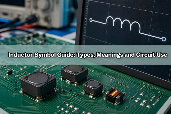
The inductor symbol is normally drawn as a coil or a row of curved loops. Extra lines, arrows, taps, or dots may identify an adjustable winding, magnetic core, intermediate connection, or magnetic coupling.
Recognizing the mark is only the first step. A schematic symbol identifies electrical function, but it does not contain enough information to purchase or assemble the physical part. Engineers must also confirm inductance, tolerance, current ratings, DC resistance, frequency behavior, package, footprint, and operating temperature.
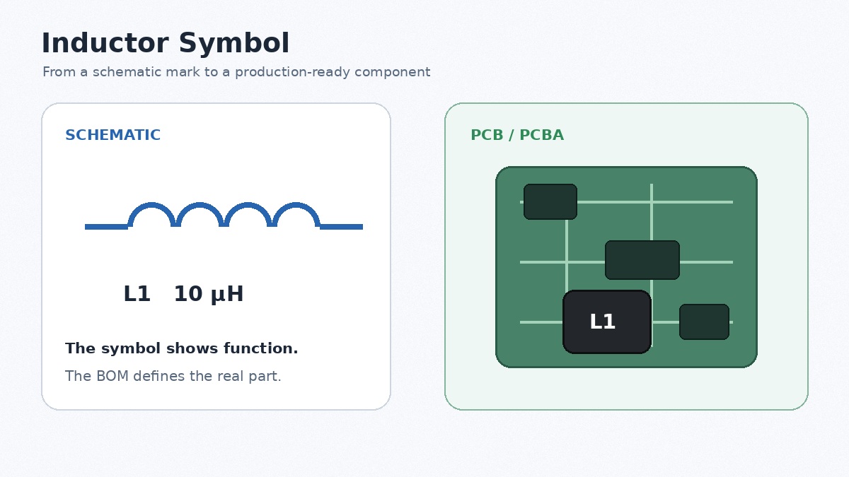
What Is an Inductor Symbol and What Does It Mean?
An inductor symbol represents a passive component that stores energy in a magnetic field while current flows through it. The familiar coil shape comes from the traditional construction of conductive wire wound around air or a magnetic core.
A basic inductor has one winding and two terminals. Its ideal voltage-current relationship is:
The voltage across the part is proportional to the inductance and the rate at which current changes. This is why an ideal inductor resists sudden changes in current. Its stored magnetic energy is:
In practical circuits, inductors provide energy storage, ripple-current control, filtering, impedance matching, and EMI suppression. The symbol does not reveal whether the physical part is wire-wound, multilayer, molded, shielded, toroidal, or intended for RF use. Those details come from the BOM and datasheet.
Why Is Inductance Represented by L, and What Is Its Unit?
Inductance is represented by L. The letter is commonly associated with Lenz’s law, although historical explanations vary. The SI unit is the henry, written as H.
| Marking | Meaning | Example |
|---|---|---|
| L | Inductance as a physical quantity | L = 10 µH |
| L1, L2 | Reference designators | L1 identifies one BOM item |
| H | Henry, the SI unit | 1 H |
| mH | Millihenry | 10 mH |
| µH | Microhenry | 4.7 µH |
| nH | Nanohenry | 22 nH |
For example, “L1 4.7 µH” combines a reference designator with a nominal value. L1 links the part to the BOM and PCB layout, while 4.7 µH states its inductance.
An inductor’s ideal AC reactance is XL = 2πfL. Reactance rises with frequency, but a real part also has winding resistance and parasitic capacitance. Above its self-resonant frequency, it may no longer behave mainly as an inductor. RF selection therefore requires the SRF and Q factor, not only the nominal value.
What Are the Main Types of Inductor Symbols?
Inductor symbols are modified to show circuit function rather than package appearance.
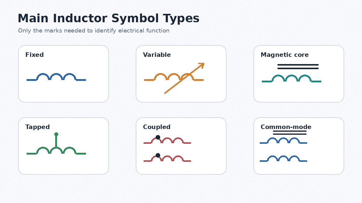
| Type | Common symbol feature | What it communicates |
|---|---|---|
| Fixed inductor | Single coil | A fixed nominal inductance |
| Variable inductor | Coil with a diagonal arrow | The inductance can be adjusted |
| Magnetic-core inductor | Parallel lines beside the coil | A magnetic core is present |
| Tapped inductor | Connection from the winding | An intermediate terminal is available |
| Coupled inductor | Two or more adjacent coils | The windings are magnetically coupled |
| Common-mode choke | Coupled windings in separate conductors | Common-mode noise filtering |
A shielded, molded, toroidal, or multilayer inductor may still use the generic fixed-inductor symbol. The exact physical construction is normally defined by the selected manufacturer part number.
How Do Fixed, Variable, Air-Core, Iron-Core, and Ferrite-Core Inductor Symbols Differ?
The clearest graphical distinction is between fixed and adjustable inductors. Core-material differences are less consistent because ECAD libraries do not always use identical qualifying marks.
| Type | Typical symbol cue | Engineering behavior | Common use |
|---|---|---|---|
| Fixed | Plain coil | Fixed nominal value | Power conversion, filtering and RF |
| Variable | Diagonal arrow | Adjustable for tuning or calibration | RF matching and resonant circuits |
| Air-core | Usually no core lines | No magnetic-core saturation; lower inductance per volume | High-frequency and RF circuits |
| Iron or powder core | Magnetic-core qualifier | Useful energy storage; powder cores often saturate gradually | Power filters and converters |
| Ferrite core | Magnetic-core qualifier | High permeability; saturation can be more abrupt | Switching supplies, transformers and EMI filters |
The drawing alone may not distinguish ferrite, powdered iron, metal composite, or a gapped core. For power-inductor selection, compare nominal inductance, saturation current, RMS current, DCR, core loss, package height, shielding, and operating temperature.
What Do Core Lines and Dots Mean on an Inductor Symbol?
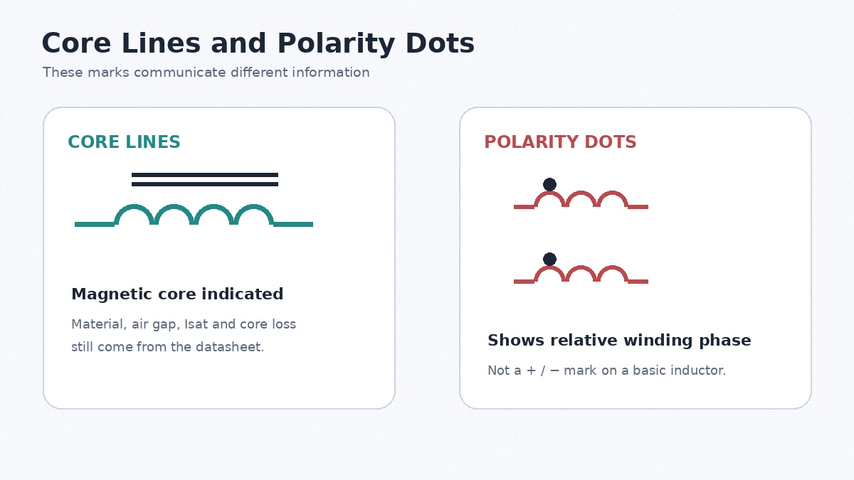
Parallel lines beside or between windings normally indicate a magnetic core. They do not identify the exact material, air gap, saturation current, core loss, or shielding performance. Those parameters remain part-specific.
Dots serve a different purpose. On coupled windings, they mark corresponding instantaneous polarity, often called winding phase. When current enters the dotted terminal of one winding, the induced voltage in the other winding is positive at its dotted terminal under the same reference convention.
The dot convention matters in coupled inductors, transformers, flyback converters, SEPIC converters, and common-mode chokes. It is not a positive or negative marking for an ordinary two-terminal inductor.
How Do IEC and ANSI/IEEE Inductor Symbols Differ?
IEC and legacy ANSI/IEEE documentation can use different coil geometry and qualifying marks, yet both describe the same electrical function. Modern drawings also vary between Altium Designer, KiCad, OrCAD, EAGLE, LTspice, and internal company libraries.
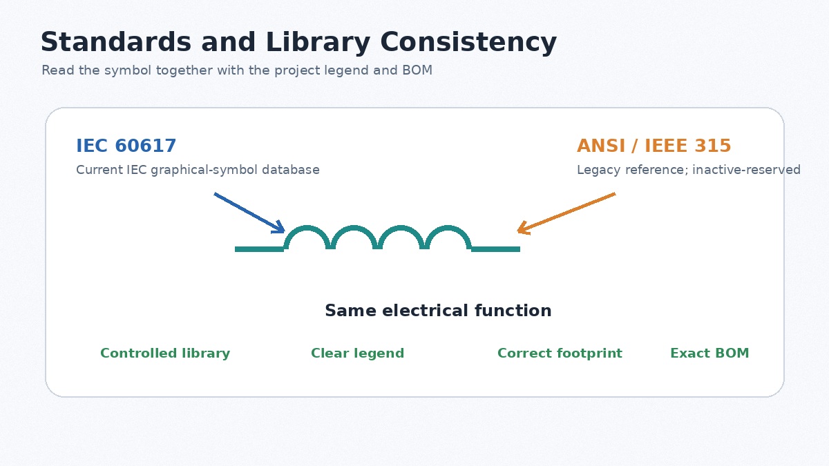
IEC 60617 is the current IEC graphical-symbol database for electrotechnical diagrams. ANSI/IEEE 315 and its supplements remain familiar references in older North American documentation, but they are listed by IEEE as inactive-reserved.
For a new design, consistency is more valuable than selecting a symbol only for regional appearance. A controlled library should define symbol geometry, reference-designator rules, pin numbering, dot placement, value formatting, and approved footprints. When reviewing legacy drawings, use the legend, BOM, and surrounding circuit to confirm meaning.
How Do You Read an Inductor Symbol in a Circuit Diagram?
Use the symbol as an entry point, then confirm the component through the design data.
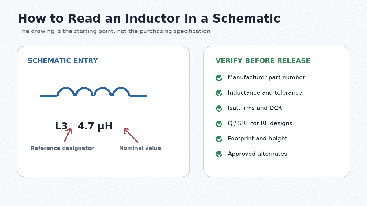
- Find the reference designator. L1 or L205 links the symbol to the BOM, assembly drawing, PCB layout, and test records.
- Read the inductance value. Confirm whether the value is in nH, µH, or mH and avoid ambiguous decimal notation.
- Check qualifying marks. An arrow indicates adjustment; parallel lines suggest a core; a tap adds a winding terminal; multiple coils and dots indicate coupling.
- Inspect the surrounding circuit. An inductor beside a switching regulator is probably an energy-storage part. One near an antenna may belong to an RF matching network.
- Match the BOM and datasheet. The schematic value alone is not a purchase specification.
- Verify the footprint. Confirm pad geometry, pin numbering, courtyard, component height, and assembly orientation.
A useful BOM entry includes the manufacturer part number, inductance, tolerance, package, Isat, Irms, maximum DCR, operating temperature, and approved alternates. RF parts may also require Q and SRF. EMI chokes may require impedance-versus-frequency data and isolation ratings.
For a turnkey PCBA quotation, EBest Circuit (Best Technology) can review the schematic for circuit context, but the production package should still include Gerber or ODB++, BOM, centroid data, assembly drawings, and exact component information. This prevents delays caused by incomplete descriptions or symbol-to-footprint mismatches.
How Is an Inductor Symbol Used in Common Circuits?
Buck Converter
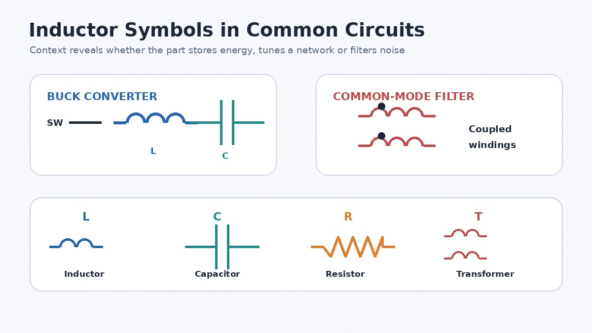
In a buck converter, the inductor sits between the switching node and output capacitor. It stores energy and limits ripple current. Selection should account for input and output voltage, switching frequency, peak current, ripple target, DCR, saturation current, and temperature rise.
Too little inductance raises ripple and peak current. Excessive inductance can increase package size, DCR, cost, and transient-response time. The part must remain within its thermal and saturation limits during startup, overload, and current limiting.
Boost Converter
In a boost converter, the inductor is commonly connected between the input supply and switching node. Peak inductor current can be much higher than output current, especially at low input voltage. Using load current alone as the selection basis can therefore produce an undersized part.
LC Filter
An inductor and capacitor can form a power or signal filter. Their values must be evaluated with source impedance, load impedance, ESR, DCR, tolerance, and damping. An undamped LC network may create ringing even when its nominal cutoff frequency appears correct.
RF Matching Network
RF inductors are used with capacitors for matching and resonance. At high frequency, Q, SRF, package parasitics, PCB pads, trace inductance, and ground-via placement can materially change the result. Two parts with the same nominal value may behave differently because of package and construction.
EMI and Common-Mode Filtering
A single inductor can attenuate differential-mode noise. A common-mode choke uses coupled windings to impede noise traveling in the same direction on multiple conductors. Evaluate the impedance curve at the actual interference frequency rather than relying only on a low-frequency inductance value.
Inductor vs Capacitor vs Resistor vs Transformer Symbols
The fastest identification method is to compare symbol shape, reference letter, and winding count.
| Component | Typical appearance | Reference letter | Main function |
|---|---|---|---|
| Inductor | One coil | L | Stores magnetic energy and resists current change |
| Capacitor | Two plates | C | Stores electric-field energy and resists voltage change |
| Resistor | Zigzag line or rectangle | R | Limits current or creates a voltage drop |
| Transformer | Two or more coupled coils | T or TR | Transfers energy or signals by magnetic coupling |
A single inductor normally has one winding and two terminals. A transformer has at least two windings and may provide isolation or a turns ratio. A coupled inductor can resemble a transformer, so the topology, winding data, isolation rating, and datasheet must also be checked.
FAQs About Inductor Symbols
1. What is the standard symbol for an inductor?
The generic symbol is a coil or series of curved loops between two terminals. Exact geometry varies between IEC, legacy ANSI/IEEE, and ECAD libraries.
2. Why is an inductor represented by the letter L?
Inductance is conventionally represented by L, often associated with Lenz’s law. The historical origin is not completely certain. Labels such as L1 and L2 identify individual components in a design.
3. What does L1 mean on a circuit diagram?
L1 is a reference designator. It connects the schematic symbol to the corresponding BOM entry, footprint, assembly location, and test record. It does not state the inductance value.
4. What is the unit symbol for inductance?
The SI unit is the henry, written as H. PCB-mounted inductors are commonly specified in mH, µH, or nH.
5. Do inductors have polarity?
Most basic two-terminal inductors do not have positive and negative terminals. Orientation can still matter for coupled, tapped, or magnetically sensitive parts and for devices with start-of-winding marks.
6. What do the lines and dots beside an inductor symbol mean?
Parallel lines normally indicate a magnetic core. Dots on coupled windings show relative winding phase. Neither mark provides a complete material or current specification.
7. What is the difference between an inductor symbol and a transformer symbol?
An inductor normally shows one winding. A transformer shows two or more magnetically coupled windings. Coupled inductors can look similar, so confirm the part from the circuit and datasheet.
Conclusion
The inductor symbol identifies an inductive function, but it does not fully define the component. Core construction, current capability, DCR, frequency behavior, package, footprint, and thermal limits must be confirmed before layout, purchasing, or assembly.
For a PCBA quotation, provide Gerber or ODB++ data, BOM, centroid files, assembly drawings, and complete inductor specifications. EBest Circuit supports PCB manufacturing, component sourcing, prototype assembly, and turnkey production. Contact sales@bestpcbs.com for project review or quotation.