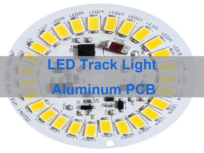
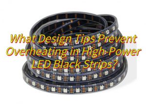
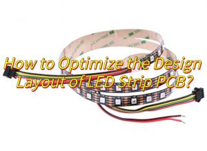
A high power LED aluminum PCB transfers heat from LED components through a thermally conductive dielectric layer and aluminum substrate to the cooling structure, helping control operating temperatures. EBest Circuit provides custom high power LED aluminum PCB manufacturing, thermal dielectric material options, SMT assembly, and volume production services for industrial lighting, LED streetlights, and other high-power lighting applications.
Are your high-power LED modules experiencing localized overheating, brightness degradation, or premature LED failure? Even with an aluminum substrate, excessive dielectric thermal resistance, poor copper distribution, or insufficient heat-sink contact can create hot spots. How can you select the right materials and PCB construction to reduce thermal resistance without compromising electrical insulation? The key is matching the LED power requirements with the dielectric material, copper layout, and actual cooling conditions.
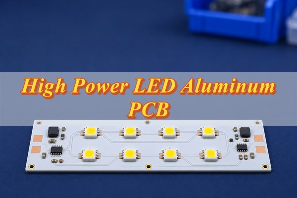
Why Do High Power LED Aluminum PCBs Overheat?
High power LED aluminum PCBs overheat when the heat generated by LEDs cannot be transferred efficiently through the PCB and cooling system. Although aluminum provides good heat-spreading performance, excessive thermal resistance anywhere along the heat-transfer path can cause localized overheating.
Common causes include:
- High dielectric thermal resistance: Low thermal conductivity or excessive dielectric thickness restricts heat transfer from the copper circuit to the aluminum substrate.
- Concentrated LED placement: Closely spaced high-power LEDs create overlapping thermal zones, increasing local temperatures.
- Insufficient copper area: Limited copper coverage around LED thermal pads reduces lateral heat spreading.
- Solder voids beneath thermal pads: Excessive voiding or insufficient solder coverage increases thermal resistance between the LED package and PCB.
- Poor heat-sink contact: Uneven board surfaces, insufficient mounting pressure, or excessive thermal interface material thickness restrict heat transfer to the external heat sink.
- Excessive driving current: Operating LEDs beyond their recommended electrical conditions increases heat generation and accelerates component degradation.
If the entire LED board operates at an elevated temperature, the external cooling system should be examined first. If only certain LEDs develop hot spots, the thermal pads, solder joints, and local copper layout require closer inspection.
How Does an Aluminum PCB Improve Heat Dissipation for High Power LEDs?
An aluminum PCB improves heat dissipation by transferring heat through a thermally conductive dielectric into a metal substrate, which spreads heat toward the external cooling structure. Its performance depends on both the PCB construction and the cooling conditions.
A typical aluminum PCB consists of three functional layers:
- Copper circuit layer: Provides electrical connections and distributes heat around LED mounting pads.
- Thermally conductive dielectric: Maintains electrical isolation between the copper and aluminum while allowing heat transfer.
- Aluminum substrate: Spreads heat from the LED mounting area and transfers it to the connected heat sink or metal housing.
Because dielectric materials generally have much lower thermal conductivity than copper and aluminum, the dielectric layer can contribute significantly to the PCB’s internal thermal resistance.
For example, increasing dielectric thermal conductivity from 1 W/m·K to 2 W/m·K can theoretically reduce the dielectric layer’s through-thickness thermal resistance by approximately 50%, assuming identical thickness and effective heat-transfer area. However, this does not mean the entire LED module will experience a 50% reduction in thermal resistance or operating temperature.
Therefore, LED junction temperature under actual operating conditions is more important than aluminum substrate surface temperature alone when evaluating thermal performance.
What Materials and Thermal Conductivity Are Best for High Power LED Aluminum PCBs?
Thermally conductive dielectric materials rated at 2-3 W/m·K are often worth evaluating for high-power LED modules with concentrated heat loads. The final selection must balance thermal resistance, dielectric strength, operating temperature, and mechanical requirements.
Common material options include:
- 1 W/m·K dielectric: Suitable for LED applications where heat density is relatively low or the cooling structure provides sufficient thermal capacity.
- 2 W/m·K dielectric: Offers lower dielectric thermal resistance for medium- to high-power LED modules requiring improved heat transfer.
- 3 W/m·K dielectric: An option for densely packed LEDs, limited cooling space, or applications with more demanding heat-transfer requirements.
- Higher-conductivity specialty materials: Can be considered when conventional aluminum PCB constructions cannot meet the required thermal performance. Material availability, electrical insulation, and manufacturing feasibility must be confirmed.
Material selection also depends on the following factors:
- Dielectric thickness: At the same thermal conductivity, a thinner dielectric generally offers lower through-thickness thermal resistance. However, it must still meet insulation voltage and long-term reliability requirements.
- Aluminum alloy: Materials such as 1060, 3003, 5052, and 6061 have different thermal conductivity, mechanical strength, and processing characteristics.
- Operating temperature: The dielectric material must withstand the expected continuous operating temperature and thermal cycling conditions without losing its insulation performance.
For extremely high heat-flux LED packages, a copper-core PCB or direct thermal path construction may be considered when a conventional insulated aluminum PCB cannot meet the junction temperature requirement.
What Are the Key Design Specifications for High Power LED Aluminum PCBs?
High power LED aluminum PCB design requires careful selection of dielectric materials, copper thickness, aluminum base thickness, LED footprints, electrical insulation, and thermal acceptance criteria. These specifications should be determined according to the LED package, operating current, heat-sink construction, and operating environment.
The following table provides common design reference values and engineering requirements.
| Design Parameter | Typical Design Reference or Requirement |
|---|---|
| Dielectric thermal conductivity | 1-3 W/m·K, selected according to thermal resistance requirements |
| Dielectric thickness | Common options around 75-150 µm, subject to insulation requirements |
| Copper thickness | Commonly 1 oz or 2 oz; 3 oz may be considered for higher-current applications |
| Aluminum base thickness | Common choices include 1.0, 1.6, and 2.0 mm |
| LED pad dimensions | Follow the LED manufacturer’s recommended land pattern |
| Trace width | Determined by current, copper thickness, allowable temperature rise, and manufacturing tolerances |
| Dielectric withstand voltage | Defined by operating voltage, overvoltage conditions, and product safety requirements |
| Maximum LED junction temperature | Must remain within the specific LED manufacturer’s datasheet limit |
| Heat-sink mounting | Define contact area, mounting-hole positions, flatness, and thermal interface material |
| Thermal testing conditions | Specify driving current, ambient temperature, measurement locations, and acceptance limits |
Several design considerations are particularly important:
- Copper thickness should not be selected from total LED module power alone. Trace width and copper cross-sectional area must match the actual current and allowable temperature rise.
- Dielectric thermal conductivity is not the same as overall PCB thermal conductivity. Material thickness, effective heat-transfer area, and interface resistance influence the actual thermal behavior.
- LED thermal pads must follow the recommended package layout. Incorrect pad dimensions, solder paste coverage, or soldering conditions can increase thermal resistance.
- Temperature acceptance criteria must be clearly defined. A single PCB surface temperature limit is generally insufficient to demonstrate that LED junction temperature requirements have been met.
For LED modules rated above 100W, actual heat dissipation should be estimated using the LED’s electrical input and optical output characteristics. A 100W electrical input does not mean that all 100W is converted into heat.
How Can High Power LED Aluminum PCBs Reduce Hot Spots and Thermal Resistance?
Reducing hot spots requires lowering localized thermal resistance, improving copper heat spreading, and maintaining reliable contact between the aluminum PCB and external heat sink.
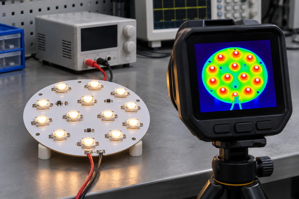
Practical improvements include:
- Optimize LED spacing: Avoid excessive concentration of high-power LEDs where the optical layout permits. Evaluate overlapping thermal zones between neighboring components.
- Increase effective copper area: Improve copper distribution around LED thermal pads while maintaining the required electrical clearances.
- Improve solder interfaces: Use suitable LED land patterns and solder paste aperture designs to reduce excessive voiding beneath thermal pads.
- Improve heat-sink contact: Control PCB backside flatness, thermal interface material thickness, and mounting pressure to minimize air gaps.
- Verify operating temperatures: Measure critical LED reference points under specified driving current and ambient conditions, then evaluate junction temperature using the manufacturer’s recommended method.
For example, a compact COB LED module may have an acceptable aluminum substrate temperature while individual LED junction temperatures remain excessive.
In this situation, increasing the heat-sink area may not solve the problem. The thermal resistance between the LED package and PCB, along with the dielectric construction, should also be examined.
What Are the Common Applications of High Power LED Aluminum PCBs?
High power LED aluminum PCBs are commonly used in lighting products that generate substantial heat, operate for extended periods, or have limited installation space.
- LED streetlights: Support high-power LED arrays for outdoor lighting and continuous operation with metal heat-sink structures.
- LED floodlights: Used in architectural, commercial, and industrial lighting where concentrated high-output LED modules require effective cooling.
- Industrial high-bay lighting: Suitable for factories, warehouses, and large facilities requiring stable thermal performance during extended operation.
- COB LED spotlights: Support compact light sources with concentrated thermal loads and demanding mounting requirements.
- LED grow lights: Help manage heat distribution across dense LED arrays and multiple lighting channels.
- Machine-vision and automotive lighting: Support compact LED installations requiring precise component positioning and reliable thermal performance.
These applications often require custom aluminum PCB shapes, LED layouts, mounting holes, and mechanical dimensions to match the lighting fixture and optical assembly.
What High Power LED Aluminum PCB Manufacturing and Assembly Services Do We Offer?
EBest Circuit provides high power LED aluminum PCB fabrication, prototyping, component sourcing, SMT assembly, and volume production. Both bare aluminum PCBs and assembled LED boards can be manufactured according to customer-approved Gerber files, BOMs, and assembly drawings.
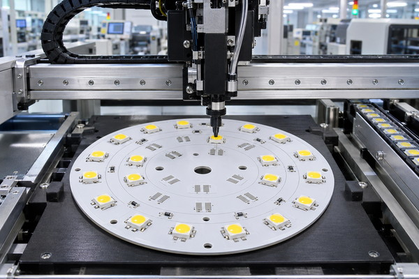
Our main services include:
- Aluminum PCB manufacturing: Fabrication of custom single-sided and applicable double-sided aluminum PCBs using specified stackups, materials, copper thicknesses, outlines, and surface finishes.
- PCB prototyping: Small-batch manufacturing for verifying LED footprint compatibility, mechanical fit, and product performance.
- LED component sourcing: Procurement of specified SMD LEDs, connectors, and supporting components, with customer-supplied materials also accepted subject to inspection.
- SMT assembly: Solder paste printing, component placement, reflow soldering, and necessary assembly inspection.
- Volume production: Repeat manufacturing and delivery based on approved fabrication specifications, BOM revisions, and order requirements.
High power LED aluminum PCBs have greater thermal mass than many conventional FR4 boards, which affects reflow soldering conditions.
The temperature profile must match the PCB construction and LED package requirements to prevent insufficient solder wetting, component displacement, or other soldering defects.
Case Study: Custom High Power LED Aluminum PCB to Reduce Overheating
Project Background
A European lighting customer required high-power LED aluminum PCBs for streetlights used in urban roads and industrial areas. The previous supplier had experienced inconsistent thermal performance, batch-to-batch quality variations, and delivery delays, disrupting the lighting manufacturer’s production schedule.
Project Requirements
- Order quantity: 5,000 boards.
- LED module power: Above 100W.
- PCB construction: Aluminum-based PCB suitable for high-power LED thermal management.
- Electrical requirements: Adequate current-carrying capacity for the LED array.
- Thermal requirements: Improve localized heat distribution and reduce hot spots.
- Delivery requirements: Maintain consistent batch quality and meet the agreed production schedule.
Challenges and Solutions
- Concentrated LED heat: LED positioning and copper distribution were adjusted to improve heat spreading around the mounting areas.
- High current requirements: A 2 oz copper construction was used to support the required current paths and increase the effective heat-spreading area.
- Inconsistent assembly quality: LED placement, soldering quality, and electrical inspection were controlled to reduce variations between assembled boards.
- Unstable delivery schedules: Material confirmation, PCB fabrication, and assembly requirements were coordinated to improve production continuity.
Project Results
EBest Circuit completed the 5,000-board production order and delivered it according to schedule. The customer subsequently continued cooperation on related LED lighting projects.
The selected aluminum PCB construction and copper layout addressed the project’s manufacturing and thermal-management concerns. Specific temperature performance depends on the LED operating conditions, heat-sink arrangement, and measurement environment.
How Do We Ensure High Power LED Aluminum PCB Quality and Reliability?
Reliable high power LED aluminum PCB manufacturing requires consistent material quality, accurate fabrication, electrical testing, and controlled LED assembly.
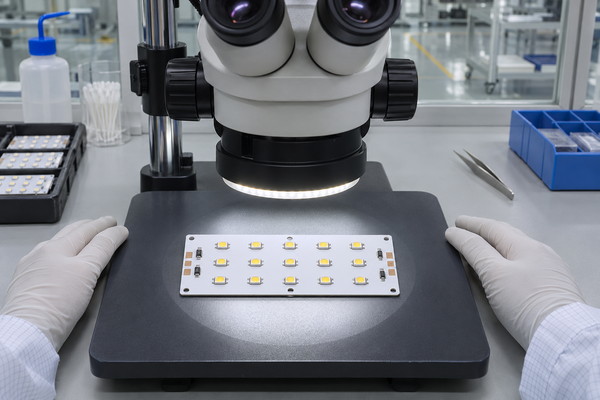
EBest Circuit applies inspection procedures according to the approved production and product requirements:
- Material inspection: Verify the aluminum substrate, copper thickness, and thermal dielectric materials against the approved specifications.
- Dimensional inspection: Check finished board thickness, outline dimensions, mounting holes, and critical LED pad geometry.
- PCB electrical testing: Identify open circuits, short circuits, and continuity defects. Dielectric withstand testing can be performed according to specified requirements.
- AOI inspection: Detect incorrect LED polarity, missing components, placement errors, and visible soldering defects.
- Functional testing: Verify LED operation and electrical functionality under the agreed test conditions.
- Additional reliability testing: Arrange temperature, thermal cycling, or other specified tests when required by the project.
EBest Circuit operates under an ISO 9001 quality management system. Relevant certification documents and applicable inspection records can be provided for customer supplier qualification.
Why Choose EBest Circuit as Your High Power LED Aluminum PCB Manufacturer?
EBest Circuit helps lighting OEMs reduce manufacturing rework, minimize risks associated with unsuitable PCB thermal constructions, and maintain more consistent production from prototypes to repeat orders.
Our advantages address the problems customers encounter during high-power LED PCB manufacturing:
- Reduce unnecessary prototype revisions: Our free DFM check reviews PCB fabrication files, LED footprints, and assembly compatibility before production. This helps identify manufacturability problems before they result in PCB rework or assembly delays.
- Avoid unsuitable thermal material selection: Experience with different thermal dielectric materials helps match the PCB construction to confirmed thermal and electrical insulation requirements, reducing unnecessary material upgrades.
- Reduce PCB and LED assembly incompatibility: Coordinated PCB fabrication and SMT assembly help ensure that pad geometry, surface finish, and LED package requirements are compatible before production.
- Improve repeat-order consistency: Approved manufacturing files, BOM revisions, and quality requirements help reduce differences between prototypes and subsequent production batches.
- Simplify sourcing and delivery coordination: With more than 20 years of PCB manufacturing experience, EBest Circuit supports bare board fabrication, component sourcing, SMT assembly, and delivery through coordinated manufacturing services.
For existing LED products with overheating problems, EBest Circuit can review customer-supplied PCB files and thermal requirements to identify manufacturing-related risks and produce aluminum PCBs according to confirmed specifications.
What Is the Lead Time for High Power LED Aluminum PCB Manufacturing and Assembly?
High power LED aluminum PCB lead time depends on material availability, PCB layer count, copper thickness, processing complexity, and assembly requirements.
| Production Type | Reference Lead Time |
|---|---|
| Standard single-sided aluminum PCB prototype | Approximately 4 working days |
| Eligible expedited single-sided prototype | As fast as 24 hours |
| Standard double-sided MCPCB prototype | Approximately 14 working days |
| Standard PCB assembly | Approximately 1 week after boards and components are ready |
| Special high-conductivity dielectric materials | Confirmed according to material and process requirements |
| Volume production | Confirmed according to quantity and specifications |
Standard MCPCB prototype schedules apply to orders that meet routine material and fabrication conditions.
Special dielectric materials, nonstandard board thicknesses, and additional reliability testing may extend lead time. International shipping and customs clearance times are calculated separately.
What Is Needed for a High Power LED Aluminum PCB Quote?
Yes. EBest Circuit can manufacture and quote both bare high power LED aluminum PCBs and assembled LED boards according to customer-supplied Gerber files, mechanical drawings, and assembly documentation.
For bare aluminum PCB quotations, please provide:
- Gerber and drill files.
- PCB dimensions, thickness, and layer count.
- Aluminum substrate, copper thickness, and thermal requirements.
- Surface finish and mechanical tolerances.
- Order quantity, required delivery date, and delivery location.
For assembled LED PCB quotations, additional information includes:
- BOM with LED manufacturer part numbers.
- Pick-and-place files and assembly drawings.
- LED polarity, binning, and component requirements.
- Functional testing and acceptance criteria.
If the Gerber files are not yet finalized, preliminary PCB dimensions, LED part numbers, thermal requirements, and estimated order quantities can be submitted for an initial manufacturing feasibility review.
FAQ About High Power LED Aluminum PCB Manufacturing
Q1: Does white solder mask improve heat dissipation in high power LED aluminum PCBs?
A1: White solder mask primarily improves visible-light reflectance rather than thermal conduction. Although its optical properties can influence lighting efficiency, actual heat dissipation still depends on the PCB thermal resistance and external cooling conditions.
Q2: Can LEDs with different color temperatures be assembled on the same aluminum PCB?
A2: Yes. LEDs with different color temperatures can be mounted on the same PCB if the electrical and optical design allows. The BOM must clearly identify LED part numbers, bin codes, and placement positions to prevent component mixing.
Q3: Can customers supply their own LEDs for assembly?
A3: Yes. Customer-supplied LEDs can be accepted for assembly. Package details, polarity, quantities, lot identification, and reflow requirements must be confirmed, and additional components should be available to cover normal assembly losses.
Q4: Can LED driver components and high-power LEDs be mounted on the same aluminum PCB?
A4: Yes, provided the layout, electrical insulation, and component operating temperature requirements are satisfied. A separate FR4 driver PCB may be more suitable for complex circuits or temperature-sensitive driver components.
Q5: Are high power LED aluminum PCBs waterproof?
A5: No. The aluminum substrate itself does not provide waterproof protection. Outdoor lighting products generally require suitable enclosures, protective materials, and sealed connections to achieve the specified ingress protection rating.
Q6: Can assembled high-power LEDs be removed and replaced?
A6: Some LED packages support rework, but controlled heating equipment and temperature profiles are necessary. Because aluminum PCBs conduct and absorb heat efficiently, improper rework may damage the LED package, copper pads, or dielectric layer.
Q7: Do aluminum PCB mounting holes require electrical insulation?
A7: It depends on the electrical design. If mounting holes are close to live copper circuits or conductive mounting hardware may contact electrically active areas, appropriate electrical clearances and insulation measures must be provided according to the operating voltage and safety requirements.
Q8: Can different BOM revisions be used within the same production order?
A8: Yes. Each BOM revision must have clearly defined component requirements, assembly documentation, and product identification. Proper revision control helps prevent component mixing and assembly errors during batch production.
Get a Quote for Your Custom High Power LED Aluminum PCB
Are localized overheating, uneven heat distribution, or LED soldering defects forcing your project into repeated prototyping and delaying mass production? Unsuitable dielectric materials, copper constructions, and assembly processes can increase thermal resistance and product failure risks, resulting in unnecessary rework and delivery delays.
EBest Circuit can help you address these manufacturing challenges with suitable thermal material options, custom high power LED aluminum PCB fabrication, SMT assembly, and quality inspection services. Whether you need bare aluminum PCB prototypes, assembled LED boards, or volume production, send your Gerber files, LED specifications, order quantity, and delivery requirements to sales@bestpcbs.com. Request your free DFM check and custom quotation to identify manufacturing risks early and move your LED project from prototype validation to reliable production.