The ferrite bead vs inductor comparison comes down to how each component handles unwanted electrical energy. A ferrite bead uses magnetic losses to dissipate noise within its effective frequency range, while a conventional inductor primarily provides reactance and stores energy. Both can help filter a PCB power rail, but their behavior changes with frequency, current, and the surrounding circuit.
EBest Circuit (Best Technology) provides PCB manufacturing and SMT assembly through its turnkey PCB and PCBA services. For boards containing small chip beads, power inductors, and local decoupling networks, this brings board production and component assembly into one manufacturing workflow. Contact sales@bestpcbs.com to discuss manufacturing your PCB or assembling your approved design.
What Is a Ferrite Bead, and How Does It Differ from an Inductor?
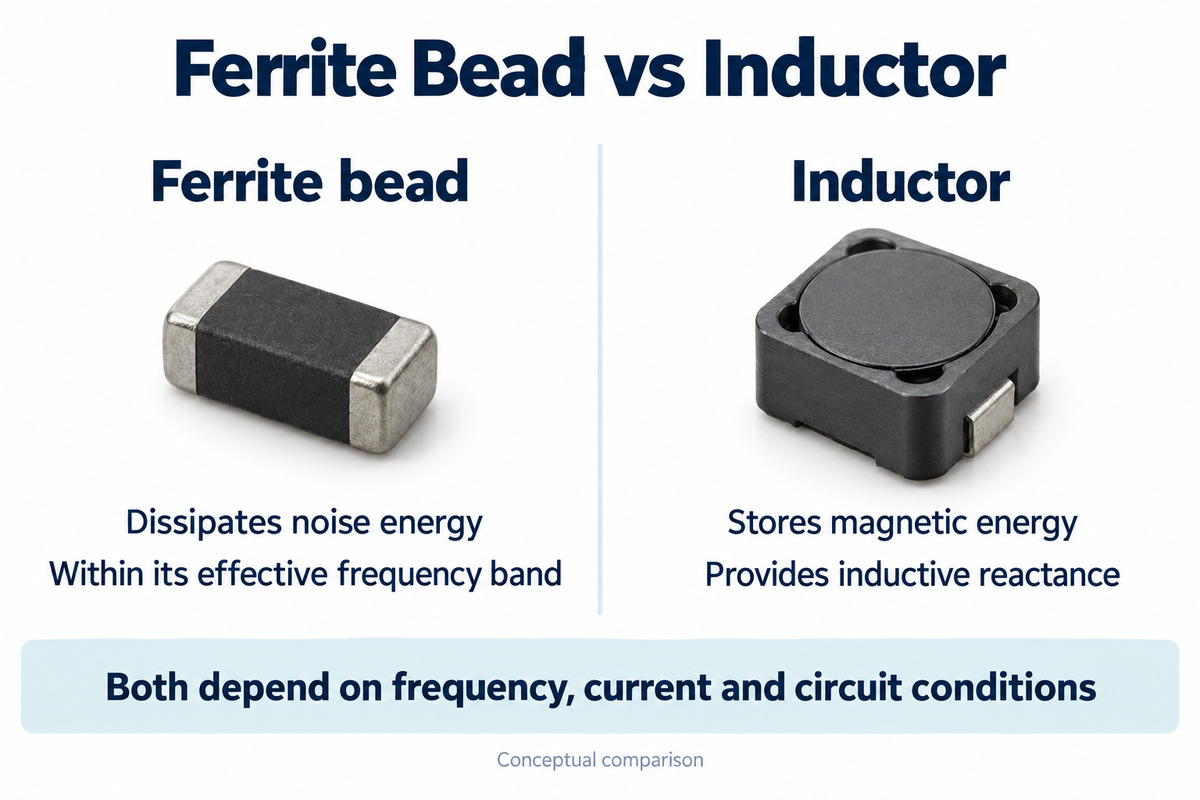
A ferrite bead is a magnetic component intended to suppress noise through frequency-dependent impedance. It belongs to the wider family of inductive components, but its ferrite material is selected to produce useful losses in the noise band.
A conventional inductor is designed around a specified inductance. Depending on the part, it may store energy in a converter, form a filter, or provide an RF impedance. Real inductors also have losses; the difference is how those losses are used.
| Characteristic | Ferrite bead | Conventional inductor |
|---|---|---|
| Main design emphasis | Lossy impedance for noise suppression | Inductance for energy storage or reactive behavior |
| Common headline specification | Impedance in ohms at a stated frequency | Inductance in nH, µH, or mH |
| Typical PCB role | Suppressing noise along a supply or suitable signal path | Converter energy storage, LC filtering, or RF circuits |
| Important limitation | Impedance can change substantially with bias current | Saturation, heating, and self-resonance limit operation |
Appearance is not a reliable guide. A chip bead may contain an internal multilayer conductor structure, and a conventional inductor may also use ferrite. The material name or package shape alone does not establish the electrical function.
How Does Frequency Change Ferrite Bead and Inductor Impedance?
A ferrite bead can behave mainly as an inductor at lower frequencies, become more resistive in its intended suppression band, and show capacitive effects at still higher frequencies. Its filtering ability therefore does not keep improving indefinitely as frequency rises.
Impedance is represented by Z = R + jX. The resistance term R accounts for loss, while X represents reactance. Two components with the same impedance magnitude at one frequency can have different proportions of R and X, producing different circuit responses.
For an ideal inductor, inductive reactance follows Xₗ = 2πfL. Actual components depart from this relationship because of winding resistance, core behavior, and parasitic capacitance. Above self-resonance, an inductor no longer behaves as the simple inductance used in that equation.
A bead marked with an impedance at 100 MHz is not being specified as a constant resistor. The useful comparison is the impedance curve over the actual noise band, including its resistive and reactive components. There is no universal frequency at which every circuit should switch from an inductor to a ferrite bead.
How Does DC Current Affect Ferrite Bead Performance?
DC current can reduce a bead’s effective impedance by changing the magnetic operating point of its ferrite. Consequently, the zero-bias curve may overstate the suppression available on a loaded power rail. The amount of change depends on the particular component.
Current ratings and bias curves answer different questions. A thermal current rating describes allowable operation under specified temperature conditions; it does not guarantee that the original impedance remains available at that current.
DC resistance also causes voltage drop and heating. Consider an illustrative calculation using a bead with 0.05 Ω DCR carrying 1 A. Its DC voltage drop is approximately V = IR = 0.05 V, and its DC conduction loss is P = I²R = 0.05 W. At 2 A, those values become 0.10 V and 0.20 W, assuming unchanged resistance. These are calculated examples, not measured component results, and exclude additional AC losses.
Power inductors also have current-dependent limits. Saturation current and thermal current ratings describe different effects, so a single ampere value cannot fully characterize either component.
When Should You Use a Ferrite Bead or an Inductor in a Power Filter?
A ferrite bead is useful when the unwanted noise falls within its effective suppression band and the supply branch can tolerate its impedance and DC losses. An inductor is useful when the circuit needs a defined inductance, including an LC filter intended to reduce lower-frequency ripple.
| Circuit requirement | Typical approach | Reason |
|---|---|---|
| Reduce high-frequency noise entering a sensitive supply branch | Ferrite bead with suitable local decoupling | Provides series impedance and loss within the targeted band |
| Attenuate ripple using a defined LC response | Filter inductor and capacitor | Inductance and capacitance establish the intended response |
| Store and transfer energy in a switching converter | Power inductor specified for that converter | Controls current change during the switching cycle |
A switching power supply can contain both components. The power inductor performs the conversion function; a separate bead may filter a downstream branch. Their presence in the same supply does not make their jobs interchangeable.
Supply behavior also matters. Adding series impedance to a rail with rapid load changes can increase voltage disturbance unless the local energy storage and overall power network support those changes. A filter appropriate for a steady analog load is not automatically suitable for a processor core rail.
Why Can a Ferrite Bead and Capacitor Amplify Noise?
A bead can remain inductive at the frequency where it resonates with a capacitor. If the network has insufficient damping, its response can peak and increase noise at the load instead of reducing it.
Low-ESR capacitors, source impedance, and load conditions all affect this behavior. A bead’s losses at a much higher frequency do not guarantee damping at the resonance frequency.
One remedy is a separately designed series RC damping branch across the filtered supply. It must be evaluated with the complete filter; arbitrary resistor or capacitor additions can change attenuation, voltage drop, or transient response. A complete response curve is more informative than one attenuation measurement.
Can a Ferrite Bead Replace an Inductor in an Existing Circuit?
A ferrite bead is not a direct replacement for a switching converter’s energy-storage inductor. That inductor must provide the required inductance throughout its operating current range and handle the converter’s ripple and peak currents. A bead’s impedance rating does not specify equivalent energy-storage performance.
In an existing noise filter, replacing an inductor with a bead may be possible, but it changes the filter. The replacement can alter attenuation, damping, DC drop, and load-transient behavior. The reverse substitution can also remove losses that were helping damp the original circuit.
Neither equal package size nor equal current rating establishes equivalence. Even matching impedance magnitudes at one frequency leaves the rest of the response unknown. Any substitution therefore needs evaluation in the actual circuit, including startup and relevant load conditions.
Where Should Ferrite Beads Be Placed on a PCB?
Place the bead in the path through which noise is being conducted, at the boundary the filter is intended to protect. That boundary may be the supply feed to a sensitive circuit, the supply connection of a noise source, or an interface connection.
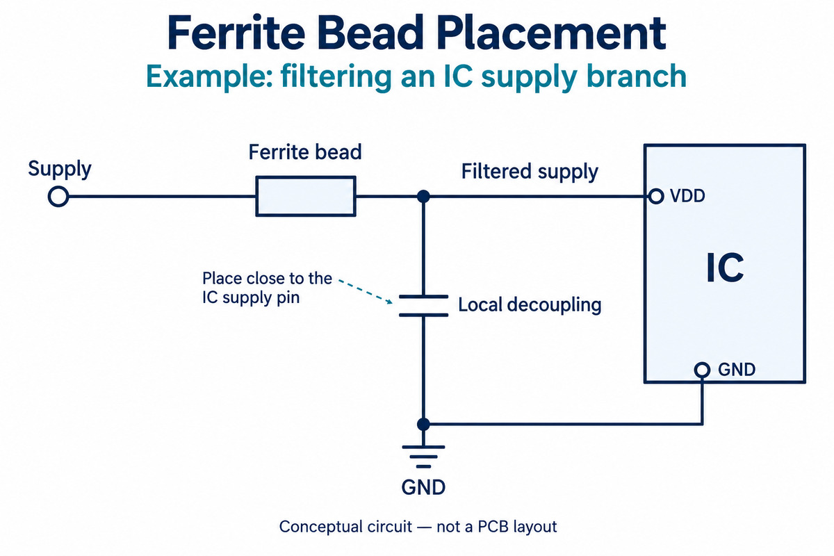
For a filtered IC supply, a typical arrangement is supply → bead → local decoupling and IC supply pin. The capacitor connects from the filtered supply to ground and should have a short connection to the IC supply and return path. The bead does not replace that local capacitor.
When the objective is to stop noise spreading from a circuit or reaching a cable, placement near the source or interface can be more effective than placing the bead at an arbitrary point elsewhere on the board. Thus, “always closest to the load” is not a complete placement rule.
The unfiltered and filtered sections should remain physically distinct enough to avoid coupling noise around the filter. Compact capacitor connections and short return paths help the real layout behave like the intended circuit. Simply adding a bead to a schematic does not correct a poor noise-current path.
FAQs About Ferrite Beads and Inductors
Is a ferrite-core inductor the same as a ferrite bead?
No. Ferrite describes a magnetic material family. A ferrite-core inductor can be designed for energy storage or reactive operation, while a bead is intended to provide useful loss for noise suppression.
Can the schematic symbol distinguish a bead from an inductor?
Not always. Symbol conventions vary between libraries. The component description, manufacturer part number, and datasheet provide a more reliable identification than the drawing alone.
What does an impedance rating at 100 MHz mean?
It gives the bead’s impedance magnitude at that frequency under the stated test conditions. It is neither the DC resistance nor a guarantee of the same impedance across all frequencies and currents.
Does a higher impedance rating always give better filtering?
No. The impedance must be useful at the actual noise frequency and operating current. Its interaction with the source, load, and capacitors determines the resulting attenuation and any resonance.
Can a ferrite bead be used on a signal line?
Yes, where its response suppresses unwanted noise while preserving the required signal spectrum. A bead suitable for a power rail is not automatically suitable for a high-speed data line.
Understanding ferrite bead vs inductor behavior helps preserve the intended function of a PCB filter through component specification and assembly. For PCB manufacturing and PCBA services for your approved circuit, contact EBest Circuit at sales@bestpcbs.com.