standard capacitor values are preferred nominal capacitances selected from repeating E-series numbers. Instead of manufacturing every possible value, suppliers offer practical steps such as 10, 15, 22, 33, 47, and 68, then scale those numbers by powers of ten. That system makes components easier to specify, source, substitute, and control in a BOM.
The printed capacitance is only the starting point. A value that is mathematically correct can still be unsuitable because of voltage rating, dielectric behavior, ESR, package size, temperature, or availability. The useful workflow is therefore: identify the target, choose the appropriate E-series value, confirm the real component, and verify it under circuit conditions.
What Are Standard Capacitor Values?
A standard capacitor value is a preferred nominal capacitance that manufacturers commonly offer. The values are organized into E-series defined for resistors and capacitors by IEC 60063. Each series divides one decade into a fixed number of approximately logarithmic steps. The same base sequence then repeats at 10 times and one-tenth of the value.
For example, 4.7, 47, and 470 belong to the same preferred-number family. With the appropriate unit, that pattern can describe 4.7 pF, 47 nF, or 470 µF. “Standard” does not mean that every manufacturer stocks every combination of capacitance, dielectric, voltage, tolerance, and package. It means the nominal number follows a preferred sequence.
Nominal capacitance is also not the same as measured or effective capacitance. A 10 µF part may legally measure within its tolerance at specified test conditions and may deliver less capacitance when DC voltage, temperature, or aging affects the dielectric.
Why Do Capacitors Follow E-Series Preferred Values?
E-series values provide useful coverage without requiring an unlimited inventory. The steps are approximately logarithmic, so the percentage gap between neighboring values stays reasonably consistent throughout a decade. A wider-tolerance series needs fewer steps; a tighter series can use more steps to offer finer choices.
The conventional relationship is E6 for about 20% steps, E12 for about 10%, and E24 for about 5%. This relationship explains the historical spacing, but it is not a promise about a modern component’s tolerance. A manufacturer may sell an E12 nominal value with a tighter tolerance, or may omit a preferred value for a particular product family.
Standardization helps an engineer avoid unnecessary custom values. It also makes second sourcing more realistic: a 22 nF or 4.7 µF requirement is easier to search, qualify, and substitute than an arbitrary value that only one vendor lists.
What Values Are Included in the E6, E12, and E24 Charts?
The E6, E12, and E24 charts contain 6, 12, and 24 normalized values per decade. The table below shows the values from 10 to below 100; multiply or divide by powers of ten to move to another decade.
| Series | Values per decade | Normalized preferred values | Conventional spacing context |
| E6 | 6 | 10, 15, 22, 33, 47, 68 | About 20% |
| E12 | 12 | 10, 12, 15, 18, 22, 27, 33, 39, 47, 56, 68, 82 | About 10% |
| E24 | 24 | 10, 11, 12, 13, 15, 16, 18, 20, 22, 24, 27, 30, 33, 36, 39, 43, 47, 51, 56, 62, 68, 75, 82, 91 | About 5% |
Thus, the E6 base value 47 can become 47 pF, 470 pF, 4.7 nF, 47 nF, 470 nF, 4.7 µF, or 47 µF. This decade-scaling rule is the practical bridge between the chart and a schematic value.
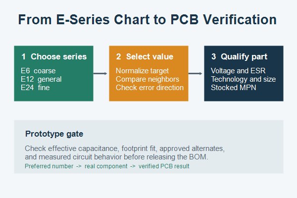
How Do You Read Capacitor Values Across pF, nF, and uF?
Capacitance units change by factors of 1,000. The core relationships are 1 µF = 1,000 nF and 1 nF = 1,000 pF. Therefore, 1 µF = 1,000,000 pF. The ASCII form “uF” is often used when a CAD tool or database cannot preserve the µ character.
| µF | nF | pF | Same capacitance |
| 1 | 1,000 | 1,000,000 | 1 µF = 1,000 nF = 1,000,000 pF |
| 0.47 | 470 | 470,000 | 0.47 µF = 470 nF |
| 0.1 | 100 | 100,000 | 0.1 µF = 100 nF |
| 0.047 | 47 | 47,000 | 0.047 µF = 47 nF |
| 0.001 | 1 | 1,000 | 0.001 µF = 1 nF |
Use the unit that produces the clearest number. Writing 100 nF is usually easier to scan than 0.1 µF, although both are correct. Consistent units in the schematic, BOM, AVL, and assembly drawing reduce factor-of-1,000 errors. For more notation examples, see the microfarad symbol and conversion guide.
How Do You Find the Nearest Standard Capacitor Value?
Find the nearest value by normalizing the target, comparing its two neighboring E-series values, and checking the permitted error direction. Use the following sequence:
- Normalize the target: Write the target in one unit, such as 36 nF.
- Select the series: Choose the candidate series, such as E12.
- Locate the neighbors: Compare 36 with the neighboring E12 values, 33 and 39.
- Calculate the error: Find the signed difference from the target.
- Check the allowed direction: Determine whether the circuit permits rounding upward, downward, or only within a defined range.
- Confirm the real part: Verify availability with the required voltage, dielectric, tolerance, and package.
For 36 nF, 33 nF is 3 nF low and 39 nF is 3 nF high. The numerical tie does not decide the circuit result. In a timing, filter, compensation, or resonant network, evaluate which direction keeps the complete transfer function inside its limit. For decoupling or bulk storage, a higher nominal value may appear attractive, but stability, inrush, ESR, size, and effective capacitance still matter.
How Should You Choose Between E6, E12, and E24 Values?
Choose the coarsest series that satisfies the circuit, then verify real part availability. E6 is useful when the circuit tolerates broad steps and part simplification is valuable. E12 gives a practical middle ground for many general-purpose designs. E24 provides finer adjustment for analog thresholds, filters, timing, or tuning, but only when component tolerance and operating drift do not overwhelm the smaller step.
| Decision factor | E6 | E12 | E24 |
| Value resolution | Coarse | Moderate | Fine |
| Typical use | Broad-tolerance functions and inventory reduction | General-purpose value selection | Closer targeting and adjustment |
| Main risk | Large gap from calculated target | May still miss a narrow window | False precision if tolerance and drift dominate |
| Required check | Manufacturer availability and worst-case circuit analysis | ||
Do not select E24 merely because it offers more numbers. A nominal 36 nF value with ±10% tolerance does not necessarily control a circuit more tightly than a carefully analyzed 33 nF value with a better dielectric and tolerance.
How Do Available Standard Values Differ Among Ceramic, Film, and Electrolytic Capacitors?
The preferred-number system is shared, but stocked values and operating limits differ by capacitor technology. Ceramic capacitors cover very small capacitances through multi-microfarad values and are common in compact surface-mount packages. Film capacitors are attractive for stability, low loss, pulse handling, or selected high-voltage applications, but often occupy more board area. Aluminum electrolytics commonly cover larger capacitance ranges and power filtering, with polarity, ESR, ripple current, and lifetime constraints.
| Technology | Selection strength | Important limitation | PCB/BOM check |
| Ceramic/MLCC | Small package, low inductance, broad availability | DC bias, temperature characteristic, aging | Effective capacitance at operating voltage |
| Film | Stability, low loss, pulse capability | Larger size and a less dense catalogue in some ranges | Lead spacing, body clearance, pulse/voltage data |
| Aluminum electrolytic | High capacitance and bulk energy storage | Polarity, ESR, ripple, temperature, lifetime | Diameter, height, polarity marking, endurance rating |
A standard 10 µF value therefore does not identify an interchangeable component. A 10 µF MLCC, film capacitor, and electrolytic can have very different voltage behavior, impedance, footprint, polarity, and cost.
When Should You Combine Capacitors to Create a Non-Standard Value?
Combine capacitors only when no single qualified part meets the target or the network provides another verified benefit. In parallel, capacitances add: Ctotal = C1 + C2 + …. A 33 nF and 3.3 nF capacitor in parallel produce a nominal 36.3 nF.
For two capacitors in series, Ctotal = (C1 × C2) / (C1 + C2). Two equal capacitors in series produce half the capacitance. Voltage does not always divide equally, especially when leakage differs, so series stacks require voltage-sharing analysis and may need balancing components.
A network adds placements, pads, assembly opportunities, tolerance contributors, and procurement lines. Prefer one qualified part when it meets the requirement. Use combinations when analysis shows the circuit benefit justifies the extra PCB area and manufacturing complexity.
Why Can an MLCC’s Effective Capacitance Be Lower Than Its Nominal Value?
Class II MLCCs can deliver less effective capacitance as applied DC voltage increases. Package size, dielectric formulation, rated voltage, nominal capacitance, temperature, and aging all influence the result. Two parts with the same 10 µF label can therefore deliver different effective capacitance on the same rail.
Do not estimate DC-bias loss from the nominal value alone. Use the manufacturer’s capacitance-versus-DC-bias curve at the intended voltage and consider tolerance, temperature characteristic, and aging in the worst-case budget. The nominal marking remains 10 µF; the capacitance available to the circuit may be substantially lower.
This distinction is particularly important for regulator stability, hold-up time, filtering, and sensitive analog networks. The SMD capacitor selection guide provides additional context on package, polarity, and technology choices.
How Do Voltage Rating, ESR, and Package Size Affect PCB Capacitor Selection?
Capacitance alone cannot qualify a PCB capacitor. Voltage rating establishes a limit, not a universal operating recommendation. Apply the derating required by the capacitor technology, environment, applicable standard, and manufacturer. For MLCCs, a higher voltage rating or larger package may also improve effective capacitance, but the actual bias curve must confirm it.
ESR changes heat generation, ripple behavior, damping, and power-supply stability. A replacement with the same capacitance but much lower or higher ESR can alter circuit behavior. Use impedance and ESR data at the relevant frequency and temperature rather than relying on a single headline value.
Package size affects land pattern, assembly clearance, voltage capability, mechanical stress, and parasitic inductance. A smaller MLCC may have lower loop inductance but can lose more capacitance under bias and may be more sensitive to board flex. Placement also matters: decoupling capacitors need a short current loop, appropriate plane/via connections, and a verified return path. Review the manufacturer footprint and the capacitor PCB design considerations before releasing the layout.
How Should Capacitor Values Be Verified in the BOM and Prototype?
Verification must connect the calculated value to an exact manufacturer part number and measured prototype behavior. A generic “10 µF, 16 V, 0805” description is not enough when dielectric, tolerance, thickness, and DC-bias performance determine the result.
- Define the acceptance window: Record the design target and permitted capacitance range.
- Lock the exact specification: State the manufacturer part number, technology, tolerance, rated voltage, case size, and temperature range.
- Calculate the worst case: Determine effective capacitance at the actual voltage and temperature.
- Qualify alternates: Compare substitutes against the same functional limits instead of nominal capacitance alone.
- Check PCB fit: Verify footprint, height, polarity, courtyard, placement, and assembly access.
- Measure the prototype: Document frequency, test voltage, bias, temperature, and fixture conditions.
- Release the evidence: Complete the relevant functional and environmental tests, then record the approved BOM revision.
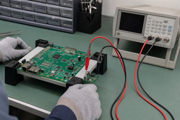
Do not compare an in-circuit reading directly with a catalogue tolerance unless the measurement method isolates the component and matches the specified test conditions. Parallel circuit paths, fixture capacitance, meter frequency, and residual charge can distort the result.
FAQs About Standard Capacitor values
Q1: What are standard capacitor values?
A1: They are preferred nominal capacitances. Common sequences include E6, E12, and E24, scaled across pF, nF, and µF decades.
Q2: What are standard values for ceramic disc capacitors?
A2: Ceramic discs commonly use preferred E-series values. The available range depends on dielectric, voltage, tolerance, lead spacing, and manufacturer, so check the exact product series.
Q3: Is there a standard capacitor values table?
A3: Yes, E6, E12, and E24 tables provide the reference. They list 6, 12, and 24 preferred numbers per decade, which scale by powers of ten.
Q4: Are E12 capacitor values always 10% tolerance?
A4: No, E12 does not guarantee 10% tolerance. The spacing has that historical association, but a modern part can specify a different tolerance.
Q5: What is the smallest standard capacitor value?
A5: There is no universal smallest standard value. Preferred numbers repeat into lower decades, while practical minimums depend on construction, package, parasitics, and manufacturer range.
Q6: Are standard SMD capacitor values different from through-hole values?
A6: The preferred numbers can be the same. Available capacitance, voltage, dielectric, and tolerance combinations differ by package and technology; SMD is not a separate E-series.
Q7: How do I convert standard capacitor values from nF to µF?
A7: Divide the nF value by 1,000. For example, 100 nF equals 0.1 µF, while 47 nF equals 0.047 µF.
Q8: Can I replace a capacitor with the nearest standard value?
A8: Only when the circuit tolerates the substitution. Check the direction of error because timing, filter, compensation, resonant, and regulator circuits can be sensitive.
Q9: Can I use a higher voltage capacitor with the same capacitance?
A9: Often, but not automatically. Confirm package size, dielectric, ESR, ripple, polarity, effective capacitance, safety class, and circuit behavior.
Q10: Why is a measured capacitor value different from its nominal value?
A10: Measurement conditions and operating stress can change the result. Check tolerance, frequency, test voltage, DC bias, temperature, aging, fixture capacitance, and parallel circuit paths.
Conclusion
standard capacitor values turn an unlimited numerical range into practical E6, E12, and E24 choices. Start with the correct chart and unit, calculate the nearest acceptable value, and then verify technology, voltage, ESR, package, effective capacitance, and availability. The final decision is not complete until the exact part and its approved alternates pass BOM, layout, and prototype checks.
For PCB design review, component sourcing, prototype assembly, or production support, email sales@bestpcbs.com with your schematic, BOM, PCB files, operating voltage, and capacitor selection requirements.