Diode direction flow tells you which way current can pass through a diode in a circuit. In normal use, conventional current flows from the anode to the cathode when the diode is forward biased. When the diode is reverse biased, a standard diode blocks current except for tiny leakage.
This guide explains the diode symbol, physical stripe, voltage direction, rectifier path, power loss, and real PCB inspection. It also helps avoid common mistakes during circuit review, repair, PCB assembly, and component sourcing.
What Is Diode Direction Flow?
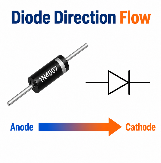
Diode direction flow means the allowed current direction through a diode. A diode is a polarized component, so its two terminals do not work the same way. One side is the anode, and the other side is the cathode.
In a normal diode, current flows mainly in one direction when the circuit is forward biased. This behavior allows diodes to work in rectifiers, reverse-polarity protection, signal control, voltage clamps, and power input circuits.
For PCB work, diode direction flow must match the schematic, footprint, silkscreen, and real component marking. If one of these is wrong, the circuit may fail even when the diode itself is not damaged.
How Can You Tell Diode Direction Flow from the Diode Symbol?
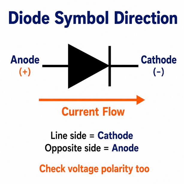
The diode symbol shows current flow from anode to cathode. In most circuit diagrams, the vertical line side of the diode symbol is the cathode. The opposite side is the anode.
A simple way to read the symbol is to follow the current toward the line. This means the current enters the anode side and exits the cathode side when the diode is forward biased.
However, the symbol alone does not prove the diode is conducting. You must also check the voltage polarity around it. The diode symbol shows the allowed path, while the circuit voltage decides whether that path is active.
| Mark | Meaning | Current Role |
|---|---|---|
| Anode | Non-line side | Current enters |
| Cathode | Line side | Current exits |
| Body stripe | Physical cathode mark | Matches symbol line |
| PCB line mark | Cathode side on footprint | Guides assembly |
Which Direction Does Current Flow Through a Diode?
Current flows through a diode from anode to cathode when the diode is forward biased. This is the standard diode conventional current direction used in circuit diagrams, PCB reviews, repair work, and assembly documents.
For a common silicon diode, clear conduction usually starts when the forward voltage reaches about 0.6V–0.7V. Schottky diodes normally have a lower forward voltage, so they are often used in low-loss or fast-switching circuits.
LEDs also follow the same current direction, but their forward voltage depends on color and material. Zener diodes act like normal diodes in forward bias, but they are often used in reverse bias for voltage regulation.
This is why current flow direction in diode checks should not rely only on the symbol. The diode type, voltage level, package marking, PCB footprint, and circuit path must all match before the direction can be confirmed.
Does Diode Current Flow from Anode to Cathode?
Yes, diode current flows from anode to cathode when conventional current is used. This is also called diode anode to cathode flow. It is the direction most circuit diagrams and PCB assembly documents follow.
The condition is important: the anode must be at a higher voltage than the cathode by enough voltage to turn the diode on. If the cathode is higher than the anode, a standard diode will normally block current.
On a real diode, the stripe usually marks the cathode, not the anode. During PCB assembly, that stripe should align with the cathode mark on the silkscreen or assembly drawing.
How Does Diode Voltage Direction Affect Current Flow?
Diode voltage direction decides whether the diode conducts or blocks current. If the anode voltage is higher than the cathode voltage, the diode is forward biased and can conduct. If the cathode voltage is higher, it is reverse biased and normally blocks current.
This explains diode voltage direction flow in practical terms. The diode has an allowed current direction, but voltage polarity controls whether current actually moves through that path.
In PCB troubleshooting, always compare the diode symbol with measured voltage. A diode may be installed correctly but still remain off because the surrounding circuit voltage is reverse biased at that moment.
What Happens to Diode Direction Flow in Forward Bias and Reverse Bias?
In forward bias, diode direction flow is active. In reverse bias, it is normally blocked. Forward bias means the anode is more positive than the cathode. After the forward voltage is reached, current passes through the diode.
Reverse bias means the cathode is more positive than the anode. In this condition, a standard diode blocks current except for very small leakage. This is often called reverse bias diode current flow, but in a normal diode it is not useful load current.
If reverse voltage exceeds the diode rating, the diode may break down or fail. Zener diodes are different because they are designed to work in controlled reverse breakdown.
Why Does a Diode Only Allow Current Flow in One Direction?
A diode allows one-way current because its PN junction reacts differently to forward and reverse voltage. Forward bias lowers the internal barrier and lets carriers cross the junction. Reverse bias increases the barrier and blocks normal current.
This one-way behavior is the reason diodes are used in power conversion, signal steering, input protection, and polarity control. In simple terms, a diode works like an electrical one-way valve.
The main advantage is control. The main limit is loss. A conducting diode always has forward voltage drop, and that voltage drop creates heat when current flows.
Main functions include:
- AC-to-DC rectification
- Reverse-polarity protection
- Voltage clamping
- Signal routing
- Power input safety
Can a Diode Allow Current Flow in Both Directions?
A standard diode does not normally allow useful current in both directions. It conducts in the forward direction and blocks in the reverse direction. A tiny leakage current may exist, but it is not the same as normal current flow.
There are special cases. A Zener diode conducts like a normal diode in forward bias, but its common use is reverse voltage regulation. This is the correct way to understand zener diode current flow direction.
A bidirectional TVS diode can protect against surges in both polarities. A bridge rectifier also handles both AC half-cycles, but it uses different diode pairs. This does not mean one ordinary diode conducts both ways.
How Do Diode Current and Voltage Direction Affect Power Dissipation?
Diode power loss comes from current and voltage drop. The practical rule is simple: diode power dissipation equals forward voltage multiplied by forward current. Higher current or higher voltage drop creates more heat.
This is the correct meaning behind diode power direction flow. Power does not “flow through” a diode like current direction. Instead, the diode converts part of the electrical energy into heat when it conducts.
For PCB work, check forward current, surge current, reverse voltage, package size, copper area, and thermal path. A diode can face the right direction but still fail if its power rating is too low.
| Factor | What to Check |
|---|---|
| Forward current | Normal load current |
| Surge current | Startup or fault pulse |
| Reverse voltage | Maximum blocking voltage |
| Forward voltage | Heat and efficiency |
| Package | Thermal ability |
| PCB copper | Heat spreading path |
How Does Diode Direction Flow Work in Rectifier Circuits?
Rectifier circuits use diode direction flow to convert AC into one-direction output current. In a half-wave rectifier, one diode conducts during one AC half-cycle and blocks during the other half-cycle.
In a bridge rectifier, four diodes work together. During the positive half-cycle, one pair conducts. During the negative half-cycle, another pair conducts. The load current still flows in the same output direction.
This explains bridge rectifier diode flow direction. The circuit handles both AC polarities, but each diode still follows its own one-way direction. The bridge works because the conducting path changes as the AC polarity changes.
How to Read a Diode Flow Direction Diagram?
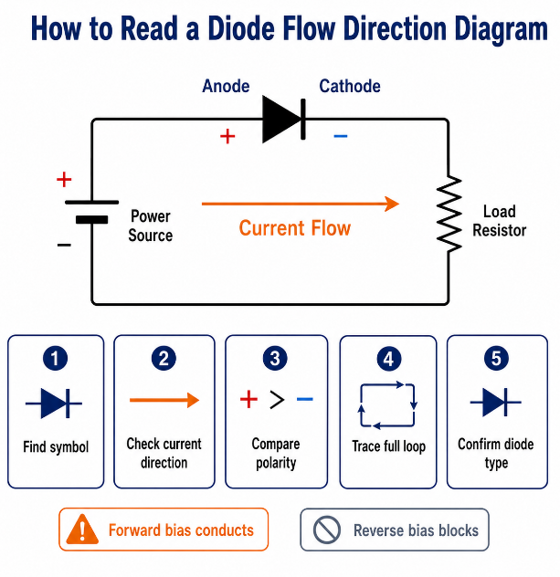
A diode flow direction diagram should be read by matching the symbol, voltage polarity, and complete circuit path. Do not judge the direction from the arrow or line alone. A diode only conducts when its terminal polarity and circuit condition support forward bias.
- Find the diode symbol first.
Locate the diode on the schematic and identify the line side. The line side is the cathode, and the opposite side is the anode. - Check the current direction shown by the symbol.
In normal forward bias, conventional current enters the anode and leaves the cathode. This is the basic diode anode to cathode flow rule. - Compare both diode terminals with the power source.
The anode should be at a higher voltage than the cathode for a standard diode to conduct. If the cathode is higher, the diode is reverse biased. - Trace the complete loop.
Current cannot flow through only one component. Check whether the path returns to the power source through a load, resistor, IC pin, ground, or another circuit branch. - Confirm the diode type.
A rectifier diode, LED, Schottky diode, Zener diode, and TVS diode may use similar symbols, but their circuit roles are different. Always check the part name and datasheet symbol. - Check whether the diagram shows real operation or only polarity.
Some drawings only mark anode and cathode. Others show active current flow. A useful diode flow direction diagram should show polarity, voltage, current path, and load direction.
How to Check Diode Direction Flow in a Real Circuit?
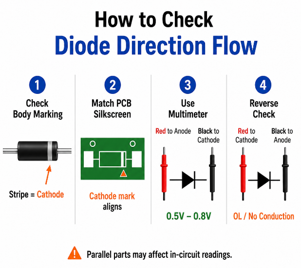
Diode direction flow in a real circuit should be checked by combining visual inspection, document review, and electrical testing. One method alone is not enough, especially in PCB assembly or repair work.
- Check the diode body marking.
On many through-hole diodes, the stripe marks the cathode. On SMD diodes, the cathode may be shown by a band, notch, groove, dot, or top mark. - Match the part with the PCB silkscreen.
The stripe or cathode mark on the component should align with the cathode mark on the PCB footprint. If the PCB marking is unclear, compare it with the schematic and assembly drawing. - Review the schematic direction.
Confirm which side is anode and which side is cathode. Then check whether the circuit expects forward conduction, reverse blocking, voltage clamping, or rectification. - Use multimeter diode mode.
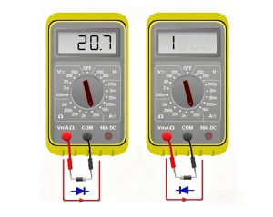
Turn off power first. Put the red probe on the anode and the black probe on the cathode. A good silicon diode often reads about 0.5V–0.8V in forward direction. - Reverse the probes.
A standard diode should usually show OL or no conduction in reverse direction. If both directions read very low, the diode may be shorted. If both directions show OL, it may be open. - Be careful with in-circuit testing.
Other components may sit in parallel with the diode and affect the reading. If the result looks wrong, lift one diode leg or remove the part before retesting. - Add production inspection for PCB assembly.
For batch PCBA work, use BOM review, footprint check, first-article inspection, AOI polarity inspection, and functional testing to reduce diode direction errors.
What Are Common Mistakes When Checking Diode Direction Flow?
Diode direction mistakes usually happen when symbol, marking, voltage, and footprint are not checked together. Each error below includes a direct solution.
- Mistake: Treating the stripe as the anode.
Solution: The stripe usually marks the cathode. Match it with the cathode line on the schematic and PCB silkscreen. - Mistake: Checking the symbol but ignoring voltage direction.
Solution: Confirm whether the anode is higher than the cathode. The symbol shows the allowed path, but voltage decides conduction. - Mistake: Using the wrong SMD footprint.
Solution: Compare the datasheet package drawing with the PCB footprint before assembly. Similar packages can have different polarity marks. - Mistake: Assuming all diodes work the same way.
Solution: Separate rectifier diodes, Schottky diodes, LEDs, Zener diodes, TVS diodes, and bridge rectifiers during review. - Mistake: Ignoring forward voltage drop.
Solution: Check the diode type and expected forward voltage. A correct direction can still cause voltage loss and heat. - Mistake: Testing a diode in-circuit without checking parallel paths.
Solution: If the multimeter reading looks abnormal, disconnect one side of the diode or remove the component for a clean test. - Mistake: Misreading bridge rectifier diode flow direction.
Solution: Remember that different diode pairs conduct in different AC half-cycles. One diode does not conduct both ways. - Mistake: Releasing PCB assembly without polarity review.
Solution: Confirm polarity through BOM, schematic, silkscreen, assembly drawing, AOI, and first-sample testing before batch production.
FAQs About Diode Direction Flow
Q1: Is the cathode always the negative side of a diode?
A1: No. The cathode is a diode terminal, not a fixed negative point. In a forward-biased standard diode, the cathode is usually at a lower voltage than the anode. In Zener clamps, TVS protection, and switching circuits, the cathode may connect to a higher-voltage node.
Q2: What does the line on a diode symbol mean?
A2: The line on a diode symbol marks the cathode. On many real diodes, the body stripe also marks the cathode. During PCB assembly, the body stripe should match the cathode line or polarity mark shown on the PCB silkscreen and assembly drawing.
Q3: Can a diode work if it is placed in the wrong direction?
A3: In most standard circuits, no. A reversed diode may block current, stop power delivery, disable a signal path, or cause a protection circuit to fail. In some protection circuits, reverse placement can also create overheating or damage nearby components.
Q4: Why does a Schottky diode have a different voltage drop?
A4: A Schottky diode usually has a lower forward voltage than a standard silicon PN diode. This makes it useful in low-voltage power paths, fast switching circuits, and circuits where reducing power loss matters.
Q5: Does diode direction matter in a flyback diode?
A5: Yes. A flyback diode is normally placed reverse biased across a relay coil, motor coil, or inductor during normal operation. When the coil turns off, the diode conducts the stored energy safely and protects the driver transistor or IC.
Q6: What is the safest way to identify an unknown diode direction?
A6: Use three checks together: body marking, datasheet package drawing, and multimeter diode mode. If the marking is unclear, do not guess from size or shape. For PCB assembly, confirm the part number and footprint before production.
Q7: Why does a diode show voltage in both directions during in-circuit testing?
A7: Other components around the diode may create another current path. Resistors, coils, IC protection pins, LEDs, or parallel diodes can affect the reading. For a reliable result, remove the diode or lift one terminal before testing again.
Q8: Can diode direction affect PCB startup failure?
A8: Yes. A reversed diode in a power input, reset circuit, bootstrap path, or protection circuit can stop the PCB from starting. It may also cause unstable voltage, blown fuses, overheated traces, or repeated power cycling during testing.
Q9: How does diode direction affect reverse-polarity protection?
A9: The diode direction decides whether the circuit blocks wrong input polarity or safely diverts fault current. A wrong diode direction can remove protection and expose ICs, capacitors, and connectors to damaging voltage.
Q10: Why do some diode packages have unclear polarity marks?
A10: Small SMD packages have limited marking space. The cathode mark may be a tiny line, dot, bevel, or laser code. Different manufacturers may mark similar packages differently, so always compare the datasheet drawing with the PCB footprint.
Q11: Does diode direction affect signal quality?
A11: Yes. Wrong diode direction can clamp the wrong voltage level, distort the waveform, increase leakage paths, or block the intended signal. This is important in communication lines, sensor inputs, ESD paths, and analog protection circuits.
Q12: What should be checked before buying diodes for PCBA production?
A12: Check package, polarity marking, voltage rating, current rating, forward voltage, reverse leakage, power rating, temperature range, and supplier traceability. For PCBA production, the diode must also match the PCB footprint and assembly drawing.
Q13: How can diode polarity errors be prevented in batch assembly?
A13: Use a complete review flow: BOM check, datasheet check, footprint review, silkscreen polarity check, SMT programming review, first-article inspection, AOI inspection, and functional test. This reduces batch failure caused by reversed or mismatched diodes.
Q14: Is diode direction different in a bridge rectifier package?
A14: Yes. A bridge rectifier package may not show four separate diode symbols on the body. Instead, it marks AC input pins and DC output pins. The safest check is to confirm the package pinout before PCB layout and before PCBA placement.
Conclusion
Diode direction flow follows one main rule: conventional current flows from anode to cathode when the diode is forward biased. In real PCB work, the diode symbol, body stripe, PCB footprint, voltage direction, diode type, and test result should all match.
A wrong diode direction can cause startup failure, overheating, signal errors, protection failure, and batch rework. Before PCBA production, diode polarity, package marking, BOM data, and assembly direction should be checked carefully.
EBest Circuit provides electronic component sourcing, BOM review, PCB manufacturing, PCBA assembly, diode polarity inspection, AOI testing, and functional test support for global projects. Send your PCB files, BOM, and assembly requirements to sales@bestpcbs.com for a quotation.