Circuit board conformal coating is a thin polymer film applied over an assembled printed circuit board to reduce damage from humidity, condensation, salt, dust, corrosive gases, and surface contamination. The right coating can improve insulation and field reliability without the weight and service restrictions of fully encapsulating the assembly.
Coating selection must match the operating environment, required service life, production method, inspection plan, and repair policy. A complete specification also preserves access to connectors, test points, adjustment devices, thermal interfaces, and other areas that must remain free of coating.
What Is Conformal Coating on Circuit Boards?
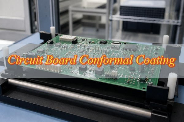
It is a thin, electrically insulating protective film. Unlike solder mask, which is applied during bare-board fabrication, conformal coating is normally applied after assembly and electrical testing. It follows the contours of components, solder joints, exposed conductors, and board surfaces while leaving specified keep-out areas uncoated.
A typical circuit board conformal coating is transparent and contains a fluorescent tracer for UV inspection. It is not automatically waterproof, hermetic, or suitable for immersion. Protection depends on the coating chemistry, film continuity, adhesion, thickness, edge coverage, cleanliness beneath the film, and compatibility with the operating environment.
| Protection Layer | Process Stage | Primary Function | Rework Implication |
| Solder mask | During bare-board fabrication, before assembly | Cover selected copper and limit unwanted solder bridging | Permanent board finish; not removed for routine component repair |
| Conformal coating | After assembly, cleaning, and initial electrical test | Thin environmental barrier and surface insulation support | Local removal may be possible, depending on chemistry |
How Does Conformal Coating Protect a Printed Circuit Board?
The film interrupts moisture and contamination paths. A continuous coating reduces direct contact between the assembly and conductive pollutants. It also increases surface insulation resistance, slows corrosion, and limits leakage or electrochemical migration when voltage bias, ionic contamination, and moisture would otherwise combine on the board surface.
The coating can also reduce the movement of fine dust, salt residue, and chemical mist toward exposed metal. Flexible chemistries may provide limited damping around small components. However, circuit board conformal coating cannot replace mechanical supports, strain relief, enclosure sealing, thermal design, surge protection, or proper ESD controls.
- Moisture barrier: slows condensation and humidity from reaching conductors and solder joints.
- Contamination control: reduces conductive paths formed by dust, salts, flux residue, and industrial deposits.
- Corrosion delay: limits oxygen, water, and reactive species at vulnerable metal surfaces.
- Insulation support: helps maintain surface resistance when coating coverage and cleanliness are controlled.
- Mechanical restraint: offers limited support against light vibration, but does not replace structural fixation.
Which Circuit Boards Need Conformal Coating?
Boards exposed to predictable environmental stress benefit most. Coating is justified when the operating or storage environment presents condensation, high humidity, salt, dust, chemical vapor, fungus risk, or frequent temperature cycling. The decision should come from an environmental risk assessment rather than a blanket rule applied to every assembly.
- Outdoor electronics: control boards inside vented or imperfectly sealed enclosures face condensation and airborne contaminants.
- Industrial controls: factory air may contain conductive dust, oil mist, cleaning chemicals, or corrosive gases.
- Transportation systems: automotive, rail, and marine electronics encounter humidity, salt, vibration, and temperature cycling.
- HVAC and appliances: temperature changes can create condensation near power and control circuitry.
- High-impedance circuits: sensor inputs and precision analog nodes are sensitive to small leakage currents.
Circuit board conformal coating may be unnecessary for a board installed in a controlled, sealed, dry indoor environment. It may also create more risk than value when unprotected switches, relays, sockets, optical surfaces, microphones, pressure sensors, or high-frequency tuning structures cannot be reliably masked.
What Are the Main Types of Conformal Coatings for Circuit Boards?
Five chemistry families cover most protection decisions. Circuit board conformal coating is commonly based on acrylic, polyurethane, silicone, epoxy, or parylene. These materials differ in chemical resistance, temperature behavior, cure method, film thickness, production equipment, and rework difficulty. UV-curable formulations form an additional production category and may use hybrid chemistry.
| Type | Main Strength | Main Limitation | Rework |
| Acrylic | Fast drying and practical general protection | Lower solvent and high-temperature resistance | Usually easiest |
| Polyurethane | Strong moisture, abrasion, and chemical resistance | Longer cure and harder removal | Moderate to difficult |
| Silicone | Wide temperature range and flexibility | Contamination control and adhesion require care | Difficult |
| Epoxy | Hard, durable, chemically resistant film | Stress, brittleness, and very difficult repair | Very difficult |
| Parylene | Uniform pinhole-resistant vapor-deposited coverage | Vacuum equipment, masking complexity, and cost | Very difficult |
| UV-curable | Rapid production cure | Shadowed regions may require a secondary cure | Formulation dependent |
Acrylic conformal coating is often the practical starting point for general electronics because it dries quickly and supports local repair. It should not be selected by habit when the assembly faces fuels, aggressive solvents, sustained high temperature, or immersion.
What Is the Best Conformal Coating for PCB?
There is no universal best coating chemistry. The best conformal coating for PCB use must survive the defined environment and adhere to the cleaned assembly. It must also fit the production process and permit the required inspection and rework. A coating that is exceptionally resistant but impossible to repair may be the wrong business and engineering choice.
- General indoor or light industrial use: evaluate acrylic where quick cure and repair access matter.
- Chemical and abrasion exposure: evaluate polyurethane or epoxy after compatibility testing.
- High temperature and thermal cycling: evaluate silicone with contamination controls.
- Complex geometry and very uniform coverage: evaluate parylene when vacuum deposition and masking are justified.
- High-volume production: evaluate UV-curable material with verified secondary cure in shadowed regions.
Circuit board conformal coating selection should compare the datasheet with operating temperature, humidity, chemicals, flammability requirements, dielectric performance, cure limitations, viscosity, application equipment, inspection method, and approved remover. Prototype boards should be coated and tested under representative stress before mass production.
What PCB Design, Cleaning and Masking Requirements Should Be Defined Before Coating?
Coating quality is largely decided before the coating is applied. Drawings should define coated zones, keep-out zones, allowable edge distance, thickness range, material designation, cure condition, inspection method, and acceptance criteria. Ambiguous notes such as “coat entire PCB” do not protect connectors, test access, adjustment points, or mating surfaces.
- Coating boundaries: show coated sides, board-edge limits, permitted overspray, minimum clearance, and areas requiring complete coverage on a controlled drawing.
- Functional keep-outs: identify connectors, sockets, contacts, switches, relays, test points, trimmers, sensors, microphones, vents, antennas, and optical surfaces.
- Thermal and grounding interfaces: exclude heat-sink contact areas, chassis grounds, press-fit zones, and mating surfaces unless the design specifically permits coating.
- Drain and shadow control: review tall components, narrow gaps, board edges, cavities, and underside regions for pooling, air entrapment, or missed coverage.
- Component spacing: leave enough access around sensitive parts for masking, inspection, local removal, soldering, and later component replacement.
- Pre-coating condition: define which assembly inspection, programming, functional test, and repair operations must be completed before coating begins.
- Cleaning process: specify approved wash chemistry, concentration, time, temperature, rinse quality, mechanical action, and compatibility with components and labels.
- Cleanliness acceptance: define visual residue limits and any required ionic contamination or surface-insulation-resistance evidence instead of relying on appearance alone.
- Drying requirement: establish drying time, temperature, handling controls, and maximum delay before coating so moisture and new contamination are not trapped.
- Material compatibility: qualify plastics, labels, inks, adhesives, thermal materials, elastomers, solder mask, and component coatings against the liquid material and cure cycle.
- Masking materials: select removable tapes, dots, boots, plugs, or custom fixtures that resist solvent, application pressure, and cure without leaking or leaving residue.
- Mask removal: define when masks are removed, how coating edges are cut if necessary, and how exposed keep-outs and lifted coating edges are inspected.
Applying circuit board conformal coating over flux, fingerprints, moisture, silicone contamination, or poorly dried wash residue traps the problem beneath the film. This can produce delamination, corrosion, leakage, bubbles, or inconsistent cure even when the coating material meets its specification.
The released process should also state who approves masking changes, how first-article coverage is verified, and which records travel with the production lot. These controls prevent an operator-level adjustment from silently changing protection or service access.
How to Conformal Coat a Circuit Board?
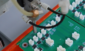
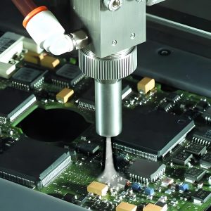
A controlled process starts with a tested and clean assembly. Brushing suits limited repair or low-volume work, spraying supports flexible coverage, dipping can coat both sides, and selective robotic dispensing provides repeatable boundaries in production. The method must match the coating viscosity, board geometry, keep-outs, and throughput.
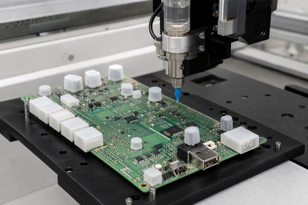
Step 1 — Verify the assembly. Complete assembly inspection, programming, and required electrical testing before coating. Confirm that repairs are closed and the approved material, thinner, masks, drawing, and process revision match the work order.
Step 2 — Clean the board. Remove flux, oils, fingerprints, particles, and other specified residues with the validated chemistry and equipment. Protect moisture-sensitive or non-washable components and use the defined rinse quality.
Step 3 — Dry and verify cleanliness. Use the approved drying profile and confirm that liquid is not trapped beneath packages, shields, or connectors. Perform the required visual, ionic, or process-based cleanliness check before further handling.
Step 4 — Mask all keep-out areas. Protect contacts, test points, switches, vents, adjustment devices, antennas, optical surfaces, and thermal interfaces. Check every mask against the controlled drawing before application.
Step 5 — Prepare the coating. Verify the material lot, shelf life, storage history, temperature, mixing ratio, agitation, filtration, viscosity, and pot life. Use only approved thinner and do not return contaminated material to the original container.
Step 6 — Apply a controlled film. Set the nozzle, spray pattern, dispense path, brush load, withdrawal speed, board orientation, passes, and flash-off time for the chosen method. Apply thin, even passes and prevent pooling beneath components or along board edges.
Step 7 — Remove masks and cure. Remove masking at the validated stage so edges remain clean without tearing the film. Cure with the specified time, temperature, humidity, UV dose, or secondary reaction while controlling board support and spacing.
Step 8 — Inspect and release. Verify coverage, keep-outs, bubbles, dewetting, thickness, cure, adhesion, and any required electrical or functional result. Record material lot, process settings, inspection result, and nonconformance disposition before releasing the assembly.
How Thick Should Circuit Board Conformal Coating Be?
Use the material specification, not one universal thickness. Many liquid conformal coatings are specified in a dry-film range around 25–125 µm, while some silicone systems may permit thicker films and parylene is commonly much thinner. The approved drawing and coating datasheet must define the actual range.
Too little circuit board conformal coating leaves pinholes, thin edges, and weak barrier performance. Too much can crack, trap solvent, bridge keep-out boundaries, increase stress around components, extend cure time, and make repair difficult. Wet-film thickness must account for solids content because the film becomes thinner as solvent evaporates.
Measure thickness on a representative coupon, witness panel, or suitable flat board location using wet-film gauges, micrometers, optical methods, or noncontact instruments appropriate to the material. Do not assume that a programmed dispense volume proves dry-film thickness across tall components and shadowed areas.
How Is Conformal Coating Cured?
Cure chemistry determines the required production controls. Different products may cure through solvent evaporation, heat, moisture, UV energy, or chemical reaction. “Dry to touch” is not the same as fully cured. A surface may feel dry while solvent remains trapped or final chemical and electrical properties are still developing.
| Cure Route | Control Point | Typical Risk |
| Ambient evaporation | Airflow, temperature, film thickness, flash time | Solvent entrapment or skinning |
| Thermal cure | Actual board temperature and dwell time | Component or material heat damage |
| Moisture cure | Humidity exposure and shadowed geometry | Slow cure in dry conditions |
| UV cure | Intensity, dose, distance, line speed, shadow cure | Uncured material beneath components |
| Two-part reaction | Mix ratio, mixing quality, pot life, temperature | Soft, brittle, or uneven cure |
Circuit board conformal coating cure records should reflect the board’s real exposure, not only the oven or lamp setting. Where a UV material uses a secondary chemical cure, production must allow enough time for shielded areas beneath tall packages and connectors to complete that reaction.
What Are the Problems with Conformal Coating PCB?
Most defects trace to contamination, application, masking, or cure. Diagnose the mechanism before reworking the board. The same visible defect can have several causes, so a repair based only on appearance may repeat the failure.
- Bubbles and pinholes: Entrained air, trapped solvent, porous residue, or fast surface drying can leave voids. Reduce agitation, control viscosity and film build, allow flash-off, and confirm that the board is clean and dry.
- Dewetting and fisheyes: Oil, silicone, flux, mold release, or an incompatible surface can repel the liquid coating. Stop production, identify the contaminant, validate cleaning, and test surface compatibility before recoating.
- Orange peel or rough texture: Incorrect viscosity, poor atomization, excessive spray distance, or rapid solvent loss can prevent leveling. Correct the material condition and spray settings, then verify the result on a representative board.
- Pooling and excessive thickness: Heavy passes, low viscosity control, poor board orientation, or insufficient drainage can collect material around components. Use thinner passes, change orientation or path timing, and verify dry-film thickness.
- Missed areas and thin edges: Component shadowing, unstable spray paths, poor wetting, or incorrect board orientation can leave exposed regions. Adjust the path, angle, speed, and number of passes, then confirm coverage under UV inspection.
- Cracking: Excessive thickness, brittle chemistry, rapid cure, or thermal and mechanical strain can fracture the film. Remove unsound material, correct film build or cure, and qualify a more flexible coating when the assembly moves.
- Whitening or haze: Moisture, solvent entrapment, incompatible cleaners, or cure conditions can cloud the coating. Verify drying, flash-off, environmental controls, and chemical compatibility before deciding whether the film must be removed.
- Delamination: Moisture, residue, poor surface preparation, or incompatible materials can lift the coating from the board. Remove loose film, clean and dry the area, confirm adhesion, and recoat only after correcting the root cause.
- Incomplete or tacky cure: Wrong mix ratio, expired material, insufficient heat or UV, excessive thickness, or shadowing can leave weak film. Quarantine the lot and verify material control, cure dose, profile, and secondary cure.
- Coating on keep-outs: Mask leakage, movement, poor fixture design, or an unstable dispense boundary can contaminate contacts and service points. Remove the coating with an approved method, correct the mask or program, and reinspect every exclusion.
Circuit board conformal coating repair should begin only after the defect mechanism is understood. Simply applying another coat over contamination, uncured material, or delamination can hide the defect and make later removal harder. When leakage or corrosion is present, isolate whether it formed before coating, under the film, or after the film was damaged.
How Is Circuit Board Conformal Coating Inspected and Tested?
Inspection must verify coverage, exclusions, cure, and performance. Visible appearance alone cannot prove that the film meets its electrical or environmental purpose. A practical control plan combines visual or UV inspection, thickness verification, cure checks, adhesion assessment, cleanliness evidence, and application-specific reliability testing.
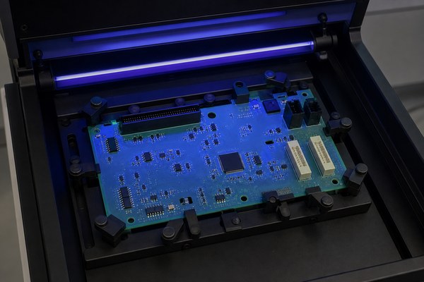
- Visible and UV inspection: confirm coverage boundaries, bubbles, cracks, pooling, foreign matter, and clean keep-outs.
- Thickness verification: measure the dry film using a method suitable for the coating and available geometry.
- Cure assessment: use the supplier’s approved tack, hardness, solvent, weight, or process confirmation method.
- Adhesion testing: validate adhesion on representative surfaces without damaging production hardware unnecessarily.
- Electrical and environmental testing: apply insulation resistance, humidity, thermal cycling, salt, fungus, or chemical exposure when the application requires it.
IPC-CC-830 is commonly used to qualify conformal coating materials, while IPC-A-610 provides workmanship acceptance guidance for electronic assemblies. Project documents should state the required revision and acceptance class. A broader PCB board testing checklist should still cover electrical and functional verification before and after the coating process.
How to Remove Conformal Coating from Circuit Board?
Identify the coating before choosing a removal method. Solvent, thermal, mechanical, peeling, and micro-abrasive methods affect each chemistry differently. The wrong remover can craze connector housings, lift labels, swell elastomers, strip markings, soften adhesives, or damage the solder mask and laminate.
Step 1 — Identify the coating and substrate. Review production records, coating appearance, supplier data, and approved repair instructions. Confirm the likely chemistry before using heat, solvent, or abrasion because the wrong method can attack plastics, markings, adhesives, solder mask, or laminate.
Step 2 — Define and protect the repair area. Mark the minimum removal boundary and shield adjacent components, contacts, and uncoated surfaces. Provide suitable extraction and personal protection for the selected chemical or abrasive process.
Step 3 — Test the removal method. Apply the proposed circuit board conformal coating remover or mechanical technique to a noncritical sample, witness coupon, or hidden region. Verify that it softens the coating without swelling plastics, lifting labels, stripping markings, or damaging the board finish.
Step 4 — Remove only the required coating. Acrylic is often softened with a compatible solvent; some silicones can be cut and peeled; polyurethane may require stronger chemical or mechanical work. Cured epoxy and parylene commonly require specialized abrasion or other controlled processes. Work from the boundary inward and avoid scraping pads or driving debris beneath packages.
Step 5 — Clean, inspect, and complete the repair. Remove softened residue and particles with an approved cleaning process. Inspect exposed conductors, solder mask, component bodies, leads, and nearby coating edges before component replacement or soldering.
Step 6 — Restore the protective system. Mask the repaired area, apply a compatible replacement coating with overlap onto sound material, complete the specified cure, and reinspect coverage, adhesion, thickness, and keep-outs. Record the repaired location and material lot when traceability is required.
Conformal Coating vs Potting: Which PCB Protection Method Is Better?
Choose by exposure, serviceability, weight, and mechanical demand. Conformal coating provides a thin, light barrier and preserves inspection and local repair access. Potting fills a cavity with a much thicker resin, offering stronger mechanical restraint and environmental isolation but adding mass, thermal constraints, cure stress, and difficult rework.
| Decision Factor | Conformal Coating | Potting |
| Protection structure | Thin film that follows the board and components | Thick resin that fills an enclosure or defined cavity |
| Moisture and contamination | Useful against humidity, condensation, dust, and chemical deposits when coverage is continuous | Stronger isolation when the resin, enclosure, interfaces, and cure are validated as a complete system |
| Mechanical support | Limited restraint; does not replace brackets, staking, or strain relief | Can immobilize components and cables, but cure shrinkage and expansion stress must be controlled |
| Weight and volume | Low material mass and minimal dimensional increase | Higher mass and volume; enclosure fill level must be controlled |
| Thermal behavior | Small thermal effect when thin, but thermal interfaces must remain clear | Can spread or trap heat depending on resin conductivity, voids, thickness, and enclosure design |
| Inspection and fault finding | Components and solder joints usually remain visible; UV tracer can show coverage | Internal features become difficult or impossible to inspect after cure |
| Repair and component replacement | Localized removal and recoating are often practical, depending on chemistry | Removal is usually slow, costly, or destructive to the assembly |
| Production controls | Cleaning, masking, viscosity, film thickness, coverage, and cure | Mix ratio, degassing, dispense volume, exotherm, voids, cure shrinkage, and adhesion |
| Best-fit application | Serviceable electronics needing lightweight environmental protection | Assemblies needing strong mechanical immobilization or deeper encapsulation |
The full conformal coating vs potting decision should also consider heat transfer, trapped air, resin exotherm, component stress, enclosure geometry, fluid compatibility, repair policy, and end-of-life requirements. Hybrid protection may use circuit board conformal coating on the assembly and localized potting around vulnerable cables or high-stress regions.
What Affects Circuit Board Conformal Coating Cost?
Total cost is driven more by process complexity than liquid price. Material chemistry matters, but masking labor, board geometry, application method, cure time, inspection, cleaning, handling, repair rate, and production volume often dominate the finished cost. Parylene requires vacuum deposition, while selective coating requires programming and fixtures but can reduce repetitive masking.
- Coated area and sides: larger boards and double-sided coverage consume more material and handling time.
- Keep-out complexity: many connectors, switches, test points, and sensors increase masking and inspection labor.
- Coating chemistry: material price, storage, pot life, cure, and removal requirements vary widely.
- Production method: brushing, spray, dip, selective dispensing, and vapor deposition have different setup economics.
- Quality evidence: thickness records, coupons, environmental testing, traceability, and special reports add controlled work.
- Rework risk: defects discovered after cure may require costly local stripping, cleaning, and recoating.
A useful quotation package includes Gerber or ODB++ data, assembly drawings, BOM, board dimensions, quantities, and the coating material or performance specification. Also provide the coated sides, keep-out drawing, thickness range, cure requirement, inspection criteria, packaging needs, and required test records.
FAQs About Circuit Board Conformal Coating
Q1: Can conformal coating change RF or antenna performance?
A1: Yes, dielectric material near an RF structure can shift its behavior. Coating over antennas, resonators, impedance-sensitive traces, or tuning elements may change capacitance, resonance, loss, or matching. Define RF keep-outs during layout and validate the fully coated assembly rather than relying only on an uncoated prototype.
Q2: Can conformal coating be used on flexible circuits?
A2: It can, but bend zones require special qualification. A coating that performs well on rigid FR-4 may crack, wrinkle, or delaminate when a flex circuit is repeatedly bent. Review minimum bend radius, dynamic versus static use, coverlay compatibility, coating modulus, thickness, and flex-cycle testing before approval.
Q3: Does conformal coating prevent tin whiskers?
A3: It may reduce whisker-related bridging risk but cannot guarantee prevention. Performance depends on coating thickness, adhesion, flexibility, coverage, and the whisker’s growth force. Whisker risk should also be controlled through finish selection, material management, stress reduction, spacing, and application-specific reliability testing.
Q4: Does the UV tracer provide any environmental protection?
A4: The tracer is primarily an inspection aid, not the protective barrier. It fluoresces under the specified UV light so missed areas, boundaries, and coverage variation are easier to see. Its presence does not prove correct thickness, adhesion, cure, cleanliness, or resistance to the intended environment.
Q5: How should opened coating material be controlled?
A5: Track storage condition, opening date, shelf life, and usable life. Moisture exposure, solvent loss, repeated opening, contamination, poor mixing, or expired material can change viscosity and cure. Production should follow the supplier’s resealing, agitation, filtration, thinning, and disposal instructions and record the material lot used.
Q6: Is conformal coating suitable for electronics used in vacuum?
A6: Only a qualified low-outgassing system should be considered. Residual solvent, uncured material, absorbed moisture, and volatile additives can contaminate optics or nearby surfaces in vacuum. Material selection should use relevant outgassing data, complete cure verification, assembly-level testing, and the actual pressure and temperature profile.
Q7: Can conformal coating justify smaller creepage distances?
A7: Do not reduce spacing without the governing safety standard and qualification evidence. Some standards recognize coated assemblies under defined material, process, pollution, and test conditions, but an ordinary coating note is not sufficient. Voltage, environment, coating category, manufacturing control, aging, and certification requirements must all be reviewed.
Q8: How should a recoated repair area be documented?
A8: Record the location, reason, materials, process, and verification result. Useful traceability includes the board serial number, removed coating type, replacement material and lot, cleaning method, repair boundary, cure condition, inspection result, and operator or station. This record supports future failure analysis and repeat-order control.
Q9: Can a cured coated assembly be cleaned after field contamination?
A9: Yes, but the cleaning agent must be compatible with the cured film. Water, detergent, alcohol, or stronger solvents can soften, swell, haze, or undermine different coatings. Identify the contaminant, test a small area, avoid forcing liquid beneath components, dry the assembly completely, and reinspect the coating afterward.
Q10: What requires requalification after a coating change?
A10: Changes to chemistry, supplier, cure, thickness, or cleaning can affect reliability. Requalification scope may include adhesion, coverage, insulation resistance, thermal cycling, humidity, chemical exposure, flammability, RF behavior, and repair compatibility. The decision should follow formal change control and the product’s risk and regulatory requirements.
Conclusion
Reliable coating begins with a defined environment and process. Select circuit board conformal coating chemistry from actual moisture, chemical, temperature, repair, and production requirements; then control cleanliness, masking, thickness, cure, and inspection. The best result is not the thickest film, but a continuous and verified barrier that protects required areas without blocking service access.
For a useful quotation, submit the assembly files, BOM, quantities, operating environment, coating material or performance requirement, keep-out drawing, thickness range, cure requirement, and inspection or test records. This information allows the manufacturing plan to address risk before coating begins.
If you are planning a PCB or PCBA project, EBest Circuit can support PCB fabrication, component sourcing, PCB assembly, conformal coating requirements, inspection, testing, prototyping, and volume production. Send your Gerber or ODB++ files, BOM, quantities, coating specification, keep-out drawing, and test requirements to sales@bestpcbs.com for an engineering review and quotation.