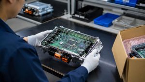
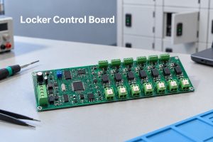
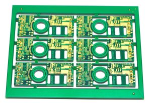
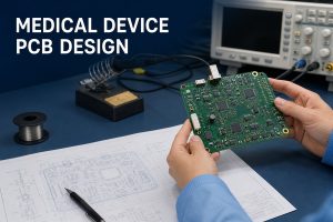
A telematics control unit connects a vehicle’s internal networks with cellular, satellite-navigation, and cloud services. It receives vehicle data, adds location or communication information, processes selected messages, and exchanges data with external platforms. That combination enables functions such as remote diagnostics, emergency calling, fleet monitoring, stolen-vehicle tracking, and over-the-air service support.
For a product team, the TCU is also a demanding electronic assembly. Wireless modules, processors, memory, vehicle-network interfaces, power protection, RF connections, and large automotive connectors must work together inside a limited enclosure. EBest Circuit can support PCB fabrication, component sourcing, PCBA assembly, manufacturing review, inspection, traceability, and customer-defined testing. To discuss a TCU board build, contact sales@bestpcbs.com with the released manufacturing data and required test scope.
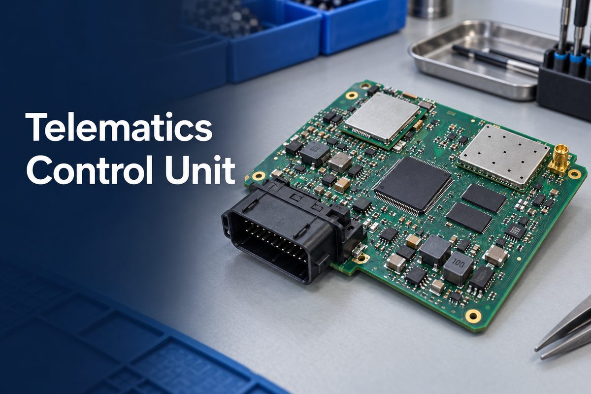
What Is a Telematics Control Unit?
A telematics control unit, usually shortened to TCU, is the electronic module that provides a vehicle with a controlled connection to external communication networks. It acts as a bridge between information available inside the vehicle and services outside it. It is also called a T-Box in some automotive markets.
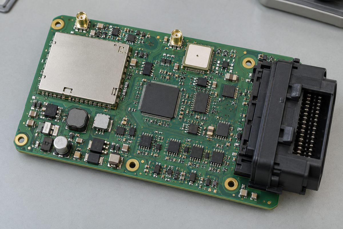
The complete unit is more than a circuit board. Depending on the product, it may include:
- an assembled PCB;
- a cellular modem and SIM or eSIM function;
- a GNSS receiver;
- a processor or microcontroller;
- memory and secure storage;
- CAN, CAN FD, LIN, or automotive Ethernet interfaces;
- Wi-Fi, Bluetooth, or V2X hardware;
- RF connectors or internal antennas;
- protected power supplies and a backup-energy function;
- firmware, security functions, an enclosure, and vehicle connectors.
The exact boundary varies by vehicle architecture. One TCU may focus on emergency calling and remote diagnostics, while another may also support Wi-Fi access, OTA communication, fleet data, infotainment services, or V2X. The released system specification—not the label “TCU” alone—determines what the hardware must contain.
This distinction also affects sourcing. A PCB supplier may fabricate the bare board, while a PCBA supplier may source components, assemble the board, program devices, and perform agreed tests. The complete telematics product still requires firmware, antennas, enclosure integration, network provisioning, security validation, and vehicle-level approval.
What Is a TCU in a Car, and What Does It Do?
A TCU collects selected vehicle information and transfers it to an external service, while also receiving authorized data or commands from outside the vehicle. It does not normally replace every other electronic control unit. Instead, it communicates with those controllers through the vehicle network.
A typical data path works like this:
- Vehicle ECUs publish status, sensor, diagnostic, or event data on an internal network.
- The TCU receives the permitted messages through CAN, CAN FD, LIN, or Ethernet interfaces.
- Its processor filters, packages, encrypts, stores, or prioritizes the information.
- A GNSS receiver can add position and time data.
- The cellular modem sends the required information to a cloud or service platform.
- Authorized responses, updates, or remote-service requests return through the controlled communication path.
This data flow can support several functions:
- automatic crash notification and emergency calling;
- remote diagnostics and fault reporting;
- location, geofencing, and stolen-vehicle tracking;
- fleet usage and maintenance information;
- remote status checks and selected vehicle commands;
- data transport for OTA software updates;
- connectivity for infotainment or onboard Wi-Fi;
- communication with external road or vehicle infrastructure.
Not every TCU supports every function. A commercial-vehicle fleet unit and an OEM passenger-car module may have different networks, environmental limits, security requirements, data rates, and service lives. Those differences change the component set, PCB complexity, assembly process, and validation plan.
What Components Are Inside a Telematics Module?
A telematics module normally combines a computing section, wireless communication section, vehicle interfaces, power conditioning, and protection. The components are selected as a system because a failure in one section can interrupt the complete data path.
| Hardware block | Typical purpose | Manufacturing concern |
|---|---|---|
| Processor or MCU | Runs communication, diagnostics, security, and control tasks | Fine-pitch package, programming, thermal load |
| Cellular modem | Connects the vehicle to mobile networks | BGA/LGA joints, controlled supply rails, RF path |
| GNSS receiver | Provides position and timing | RF sensitivity, shielding, antenna connection |
| Memory and secure device | Stores software, logs, keys, or credentials | Package orientation, programming, traceability |
| CAN/LIN/Ethernet transceivers | Connect the TCU to in-vehicle networks | ESD protection, termination, connector routing |
| Power-management devices | Convert and supervise vehicle power | Thermal dissipation, transient-rated parts, solder quality |
| RF filters and matching parts | Condition cellular, GNSS, Wi-Fi, or V2X signals | Small components, placement accuracy, approved substitutions |
| Connector system | Links power, vehicle networks, antennas, and service ports | Coplanarity, pin soldering, mechanical support |
The BOM must identify the complete manufacturer part number, package, grade, approved alternatives, and any programming or traceability requirements. A generic description such as “LTE module” or “GNSS filter” is not enough for controlled sourcing. Devices with similar commercial descriptions may differ in frequency bands, qualification status, firmware, temperature range, package revision, moisture sensitivity, or lifecycle status.
Long-lead wireless modules, processors, secure devices, automotive connectors, and memory parts deserve early supply-chain review. If an alternative part changes the footprint, RF behavior, power demand, firmware interface, or qualification status, it is an engineering change—not a routine purchasing substitution.
How Do Cellular, GNSS, and Vehicle Networks Work Together?
Cellular, GNSS, and vehicle-network circuits perform different jobs but meet at the TCU processor. Vehicle networks provide information from inside the vehicle, GNSS supplies position and timing, and cellular communication carries selected data between the vehicle and remote services.
The processor controls that exchange. It decides which vehicle messages are relevant, manages communication sessions, stores data when coverage is unavailable, and sends queued information after the connection returns. It may also coordinate Wi-Fi, Bluetooth, or V2X hardware when those functions are part of the product.
These interfaces create several hardware interactions:
- a cellular transmitter can generate noise that reduces GNSS receiver sensitivity;
- digital clocks and high-speed memory can couple noise into RF circuits;
- vehicle-network transients can enter through harness connections;
- modem transmit bursts can create rapid changes in power demand;
- enclosure, cable, shielding, and antenna placement can alter RF performance;
- sleep and wake behavior can affect both current consumption and network availability.
The PCBA must therefore preserve the separation and reference structures defined by the released design. During manufacturing review, the supplier can check whether the stackup, impedance requirements, fabrication notes, component footprints, assembly clearances, shield features, and test points are producible. The product owner remains responsible for proving antenna performance, protocol behavior, wireless certification, security, and operation in the intended vehicle.
What Makes an Automotive Telematics Control Unit Difficult to Assemble?
An automotive telematics control unit is difficult to assemble because its PCBA combines dense digital electronics, RF circuits, vehicle power, large connectors, and hidden solder joints. A process that works for a simple controller may not provide enough control for this mixture.
Depending on the released design, a TCU may combine RF sections, high-speed digital interfaces, controlled-impedance routing, and multilayer PCB stackup requirements on the same assembly.
Important production challenges include:
- Mixed component geometry: The same board may contain small RF passives, BGAs, QFNs, modules, shields, and large through-hole connectors. Stencil design and reflow settings must support different solder-volume and thermal demands.
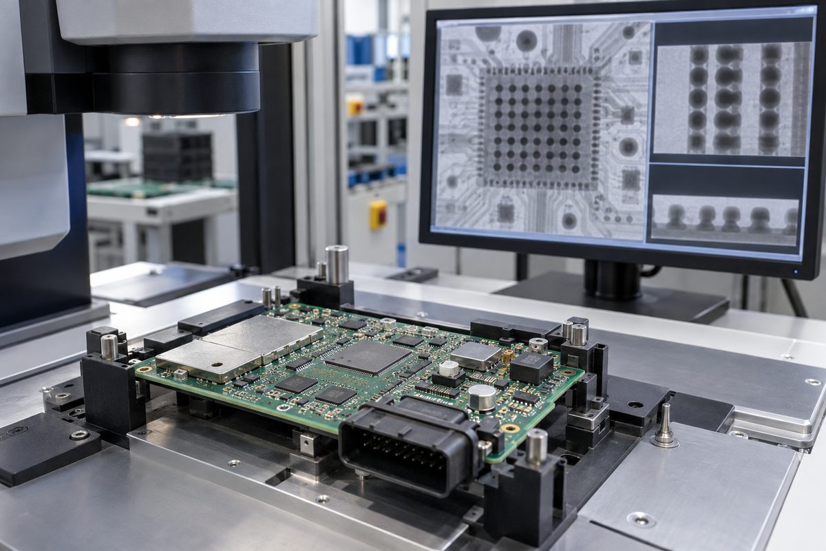
- Hidden solder joints: Modems, processors, memory, and power packages may use BGA, LGA, QFN, or bottom-terminated packages. AOI cannot see every critical joint, so the inspection plan may require X-ray.
- Module coplanarity: A wireless module with many edge or underside pads can produce opens or uneven soldering if paste deposition, placement pressure, warpage, or reflow is poorly controlled.
- RF component sensitivity: Matching components are often small and value-specific. A wrong value, rotated device, tombstone, or unauthorized alternative can change performance even when the board powers on.
- Shield and connector assembly: Shield frames, coaxial connectors, and vehicle connectors can introduce thermal imbalance, mechanical stress, or secondary soldering operations.
- Vehicle power conditions: Protection and power components may carry higher current or dissipate more heat than the digital section. Their joints, copper connections, and thermal interfaces need suitable process control.
- Programming and identity: The assembly may require boot code, secure provisioning, serial numbers, MAC addresses, or customer-specific labels. The exact responsibility and data-handling method must be agreed before production.
Manufacturing review should happen before material release. Conflicts among the Gerber or ODB++ data, BOM, pick-and-place file, assembly drawing, programming instruction, and test specification can otherwise reach the line as different interpretations of the same product revision.
Which Assembly Defects Should TCU Manufacturing Testing Detect?
TCU manufacturing testing must detect more than a board that is completely dead. An assembly defect can produce intermittent communication, weak RF performance, unexpected resets, high standby current, unreliable vehicle-network data, or failures that appear only after temperature or vibration changes.
Common defect paths include:
- insufficient solder or opens beneath BGA, LGA, QFN, and module pads;
- solder voiding beneath power or thermal pads;
- bridges around fine-pitch processors, transceivers, and connectors;
- missing, wrong-value, shifted, or tombstoned RF passives;
- poor wetting on shield frames or large ground connections;
- damaged coaxial or board-to-board connectors;
- excessive residue or contamination near high-impedance and RF sections;
- cracked joints caused by connector insertion or board handling;
- incorrect component revision or an unapproved BOM substitute;
- incomplete programming, duplicated identifiers, or mismatched firmware files.
No single inspection method finds all of these problems. SPI can verify solder-paste deposition before placement. AOI can identify visible polarity, placement, and solder defects. X-ray can examine concealed joints and voiding. Electrical tests can detect opens, shorts, supply problems, and selected component values. A functional fixture can exercise defined power, communication, and I/O behavior.
The acceptance plan should connect each important risk with an appropriate check. For example, an AOI record cannot prove cellular sensitivity, and a successful network connection cannot prove that every hidden solder joint has acceptable process quality. Inspection evidence and system-performance evidence answer different questions.
How Do You Choose a PCBA Manufacturer for a Telematics Unit?
Choose a PCBA manufacturer whose experience covers the difficult parts of the TCU assembly, not only general SMT production. EBest Circuit has experience with the component, process, inspection, and traceability controls that these mixed RF and automotive electronics projects require.
Our relevant experience includes:
- assembling BGA, LGA, QFN, RF modules, shield structures, and mixed SMT/THT boards;
- checking BOM data and complete manufacturer part numbers before purchasing;
- controlling component alternatives and obtaining customer engineering approval before release;
- managing moisture-sensitive devices and baking requirements where applicable;
- using SPI, AOI, X-ray, electrical testing, and agreed functional testing for different acceptance needs;
- supporting programming, serialization, labeling, and production-data traceability;
- completing first-article inspection before volume release;
- maintaining board, production-lot, revision, and critical-component traceability;
- working with customer fixtures, test limits, software, and golden samples;
- separating PCBA manufacturing acceptance from antenna, wireless-network, firmware, cybersecurity, and vehicle-level validation.
These controls help prevent a TCU project from being released only because the assembly looks complete. Depending on the agreed scope, production evidence can include first-article results, AOI or X-ray records for defined features, programming logs, serial-number records, electrical-test results, functional-test reports, and approved nonconformance records.
EBest Circuit can review the released PCB and assembly package, identify manufacturing conflicts, source specified components, assemble the mixed-technology PCBA, and coordinate the inspection and customer-defined testing included in the quotation. Broader automotive PCB assembly controls may also apply, while each TCU project should still define its critical components, inspection points, test limits, and required records.
FAQs About the Telematics Control Unit
Is a telematics control unit the same as an ECU?
A TCU is a type of automotive electronic control unit focused on external connectivity and telematics functions. “ECU” is the broader term for vehicle controllers. An electronic control unit board may support engine, body, chassis, battery, gateway, or other functions, while a TCU specifically manages vehicle-to-network communication and related services.
Is a TCU the same as a transmission control unit?
No. Both may use the abbreviation TCU. In this article, TCU means telematics control unit. A transmission control unit manages transmission operation and is a different automotive controller.
Does every telematics control unit include 5G?
No. The wireless technology depends on product generation, target region, service requirements, network availability, cost, and lifecycle plan. A TCU may use LTE, 4G, 5G, satellite communication, or another approved connection. The exact modem and supported bands must be defined in the product specification and BOM.
Can AOI prove that a TCU PCBA will communicate correctly?
No. AOI checks visible assembly characteristics such as component presence, position, polarity, and selected solder features. Communication performance requires suitable electrical, programming, RF, network, and system-level tests. X-ray may also be required for concealed solder joints.
What testing can a PCBA manufacturer perform for a TCU?
The available scope may include SPI, AOI, X-ray, electrical testing, programming, interface checks, and customer-defined functional testing. Antenna performance, cellular certification, GNSS performance, cybersecurity, cloud communication, vehicle integration, and regulatory approval normally require additional product- or system-level validation defined by the customer.
If you need PCB fabrication or PCBA support for a telematics control unit, send the released board data, BOM, component-placement file, drawings, programming instructions, test requirements, quantity, and required production records to sales@bestpcbs.com for review.