Lead free solder material is a tin-based alloy used to create electrical and mechanical connections without intentionally adding lead. Common PCB assembly choices include SAC305, tin-copper alloys, low-silver SAC alloys, and low-temperature tin-bismuth alloys. They differ in composition, melting behavior, wetting, mechanical response, process temperature, and cost.
For PCB buyers, “lead free” alone is not a complete solder specification. The alloy should match the assembly method, component temperature limits, PCB surface finish, reliability target, and regulatory requirements.
What Is Lead Free Solder Material?
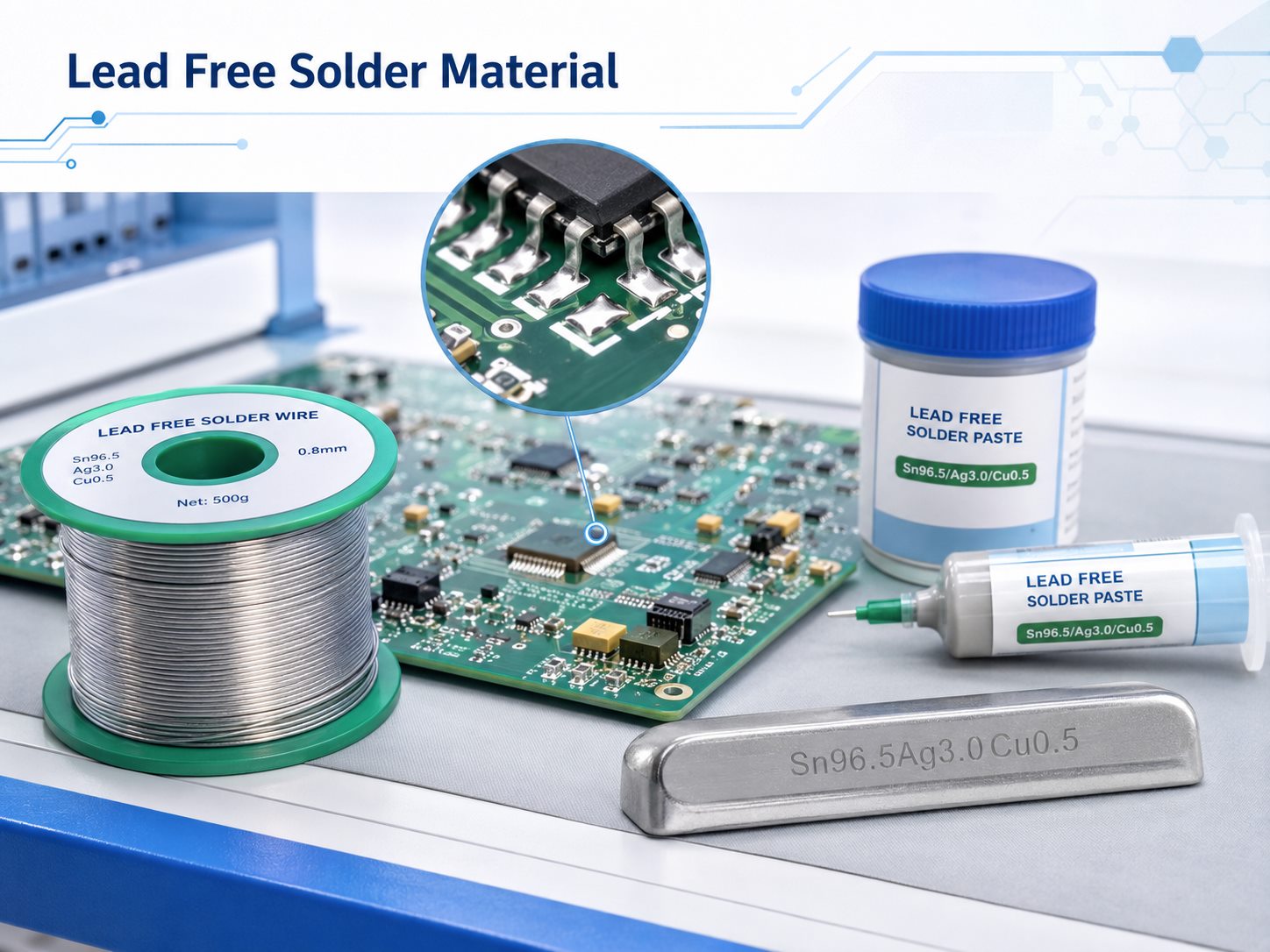
Lead free solder material is a solder alloy in which lead is not intentionally used as the primary alloying element and which meets the applicable lead-content requirement for the product. Most electronic lead-free solders use tin as the base metal, combined with silver, copper, bismuth, nickel, or other elements.
A common example is SAC305, which contains approximately 96.5% tin, 3.0% silver, and 0.5% copper.
Lead-free solder can be used for:
- SMT reflow soldering
- Wave soldering
- Selective soldering
- Hand soldering and rework
- BGA and other area-array interconnections
“Lead free” does not describe one fixed alloy. Different lead-free solder materials can have very different melting temperatures and process behavior.
What Is Lead Free Solder Made Of?
Most lead-free electronic solders are based on tin, with smaller amounts of other metals added to adjust melting temperature, strength, wetting, intermetallic formation, or solder-pot behavior.
- Tin (Sn) is normally the base metal.
- Silver (Ag) influences strength and SAC solder-joint microstructure. Higher silver content also increases material cost.
- Copper (Cu) affects intermetallic formation and solder-pot behavior.
- Bismuth (Bi) lowers melting temperature and is widely used in low-temperature solder systems.
- Nickel (Ni) may be added in small amounts to modify intermetallic behavior in some SnCu alloys.
- Germanium (Ge) and similar micro-alloy additions may help control oxidation and dross.
The required alloying elements depend on the soldering process and reliability target rather than on one metal being universally better than another.
What Are the Composition Percentages of Common Lead-Free Solder Alloys?
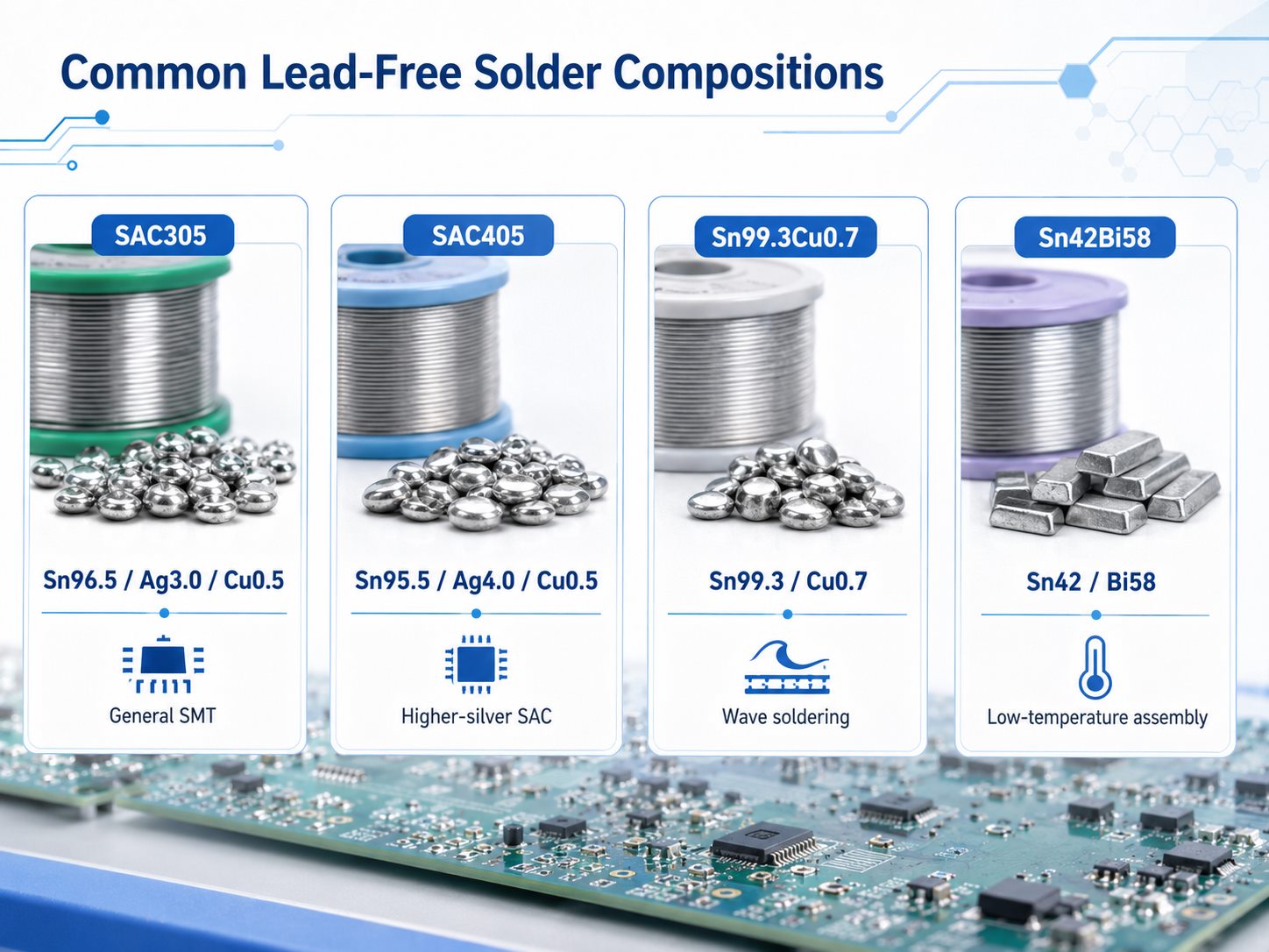
Lead free solder material composition varies by process and reliability target, with SAC305 serving as the most familiar reference.
| Lead-Free Alloy | Typical Composition by Weight | Melting Behavior | Typical Application |
| SAC305 | Sn 96.5%, Ag 3.0%, Cu 0.5% | 217–220°C | General SMT and reflow |
| SAC405 | Sn 95.5%, Ag 4.0%, Cu 0.5% | 217–225°C | Higher-silver SAC applications |
| Sn99.3Cu0.7 | Sn 99.3%, Cu 0.7% | About 227°C | Wave soldering and cost-sensitive production |
| Sn42Bi58 | Sn 42%, Bi 58% | About 138°C | Low-temperature assembly |
| Low-Ag SAC | Sn-based with reduced Ag and Cu | Alloy dependent | Cost-sensitive and application-specific assembly |
For procurement, specify the exact alloy designation when the solder composition is controlled by the drawing, qualification plan, or customer specification.
What Is the Melting Point of Lead-Free Solder?
Lead-free solder does not have one fixed melting point. The temperature depends on the alloy composition.
Typical values include:
- SAC305: approximately 217–220°C
- SAC405: approximately 217–225°C
- Sn99.3Cu0.7: approximately 227°C
- Sn42Bi58: approximately 138°C
- Sn63Pb37, for comparison: 183°C
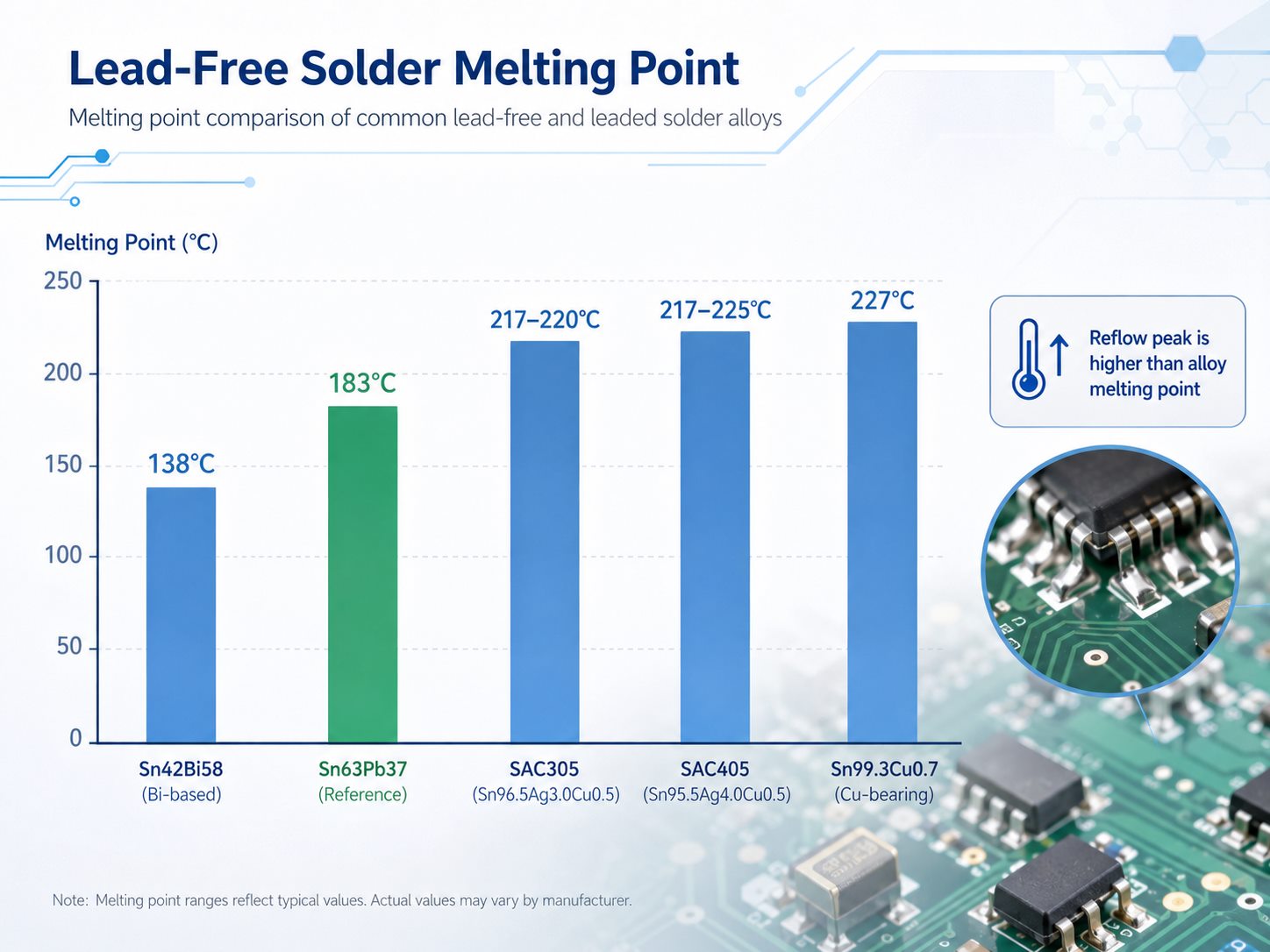
Melting temperature, soldering-iron temperature, and reflow peak temperature should not be confused.
SAC305 becomes fully liquid around 220°C, but a production reflow process typically peaks around 240–250°C, depending on solder paste specifications, PCB thermal mass, component limits, and required time above liquidus.
For heat-sensitive connectors, LEDs, flex circuits, plastics, batteries, or temperature-sensitive components, the thermal limit should be reviewed before selecting the solder alloy.
What Material Properties Matter in Lead-Free Solder?
The most relevant solder properties are those that affect manufacturability and long-term joint performance.
- Wetting behavior: affects solder spread, fillet formation, hole fill, and process margin.
- Mechanical strength: matters where solder joints experience vibration, shock, or handling loads.
- Ductility and creep: affect how the joint responds to sustained mechanical and thermal strain.
- Thermal-fatigue behavior: matters in applications exposed to repeated temperature cycling.
- Intermetallic formation: affects the interface between solder and copper or component finishes.
- Electrical and thermal properties: matter in current-carrying and thermally demanding joints.
- Oxidation and dross behavior: are especially relevant in wave and selective soldering.
These properties should be evaluated against the actual component package and operating environment.
How Does Lead-Free Solder Compare With Lead Solder?
A useful electronics comparison is leaded vs lead free solder, especially SAC305 versus traditional Sn63Pb37.
| Factor | SAC305 Lead-Free | Sn63Pb37 Leaded |
| Nominal composition | Sn96.5Ag3.0Cu0.5 | Sn63Pb37 |
| Melting behavior | 217–220°C | 183°C |
| Process temperature | Higher | Lower |
| Wetting behavior | Generally less forgiving | Generally easier |
| Joint appearance | Often duller | Typically brighter |
| Regulatory use | Common in RoHS-compliant products | Restricted unless exempt |
| Current electronics use | Mainstream | Legacy and specialized applications |
The higher thermal exposure of SAC305 can affect laminate durability, component moisture sensitivity, connector plastics, warpage, and overall process margin.
When converting an older SnPb assembly to lead-free production, the PCB and component set should be checked for lead-free reflow compatibility.
Is Lead Free Solder Really Lead Free?
“Lead free” does not necessarily mean that laboratory analysis must detect exactly 0.000% lead.
Under EU RoHS, the general maximum concentration value for lead is 0.1% by weight in a homogeneous material, unless a relevant exemption applies.
This matters when reviewing:
- alloy certificates
- RoHS declarations
- recycled solder
- mixed-process production
- legacy components
- contaminated solder pots
A purchase order should state the required compliance standard rather than relying only on the phrase “lead-free solder.”
What Forms Does Lead-Free Solder Come In?
The alloy and the product form are separate specifications.
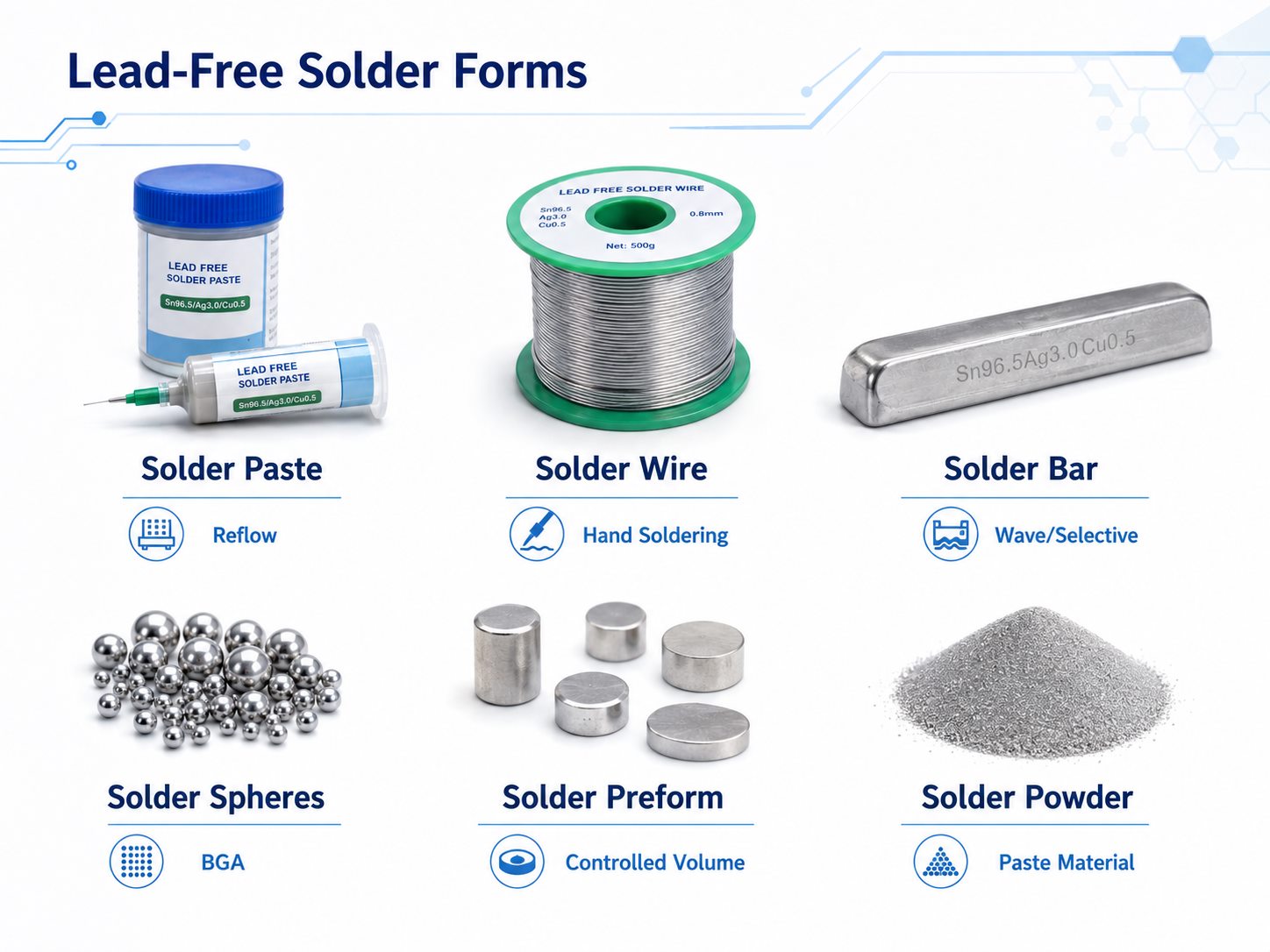
| Solder Form | Typical Use |
| Lead-free solder paste | SMT stencil printing and reflow |
| Lead-free solder wire | Hand soldering and rework |
| Lead-free solder bar | Wave and selective soldering |
| Solder spheres | BGA and CSP packages |
| Solder preforms | Controlled solder-volume applications |
| Solder powder | Main metallic constituent of solder paste |
Lead-free solder paste is not simply another name for lead-free solder alloy. Paste combines solder powder with flux and other constituents needed for printing and reflow.
For soldering wire material, buyers may also need to specify wire diameter, flux type, flux percentage, and alloy.
For solder bar, solder-pot volume, dross generation, copper dissolution, contamination control, and alloy cost become more important.
Which Lead-Free Solder Material Is Best for PCB Assembly?
There is no single best alloy for every assembly. SAC305 is a common starting point, but the soldering method and thermal constraints should drive selection.
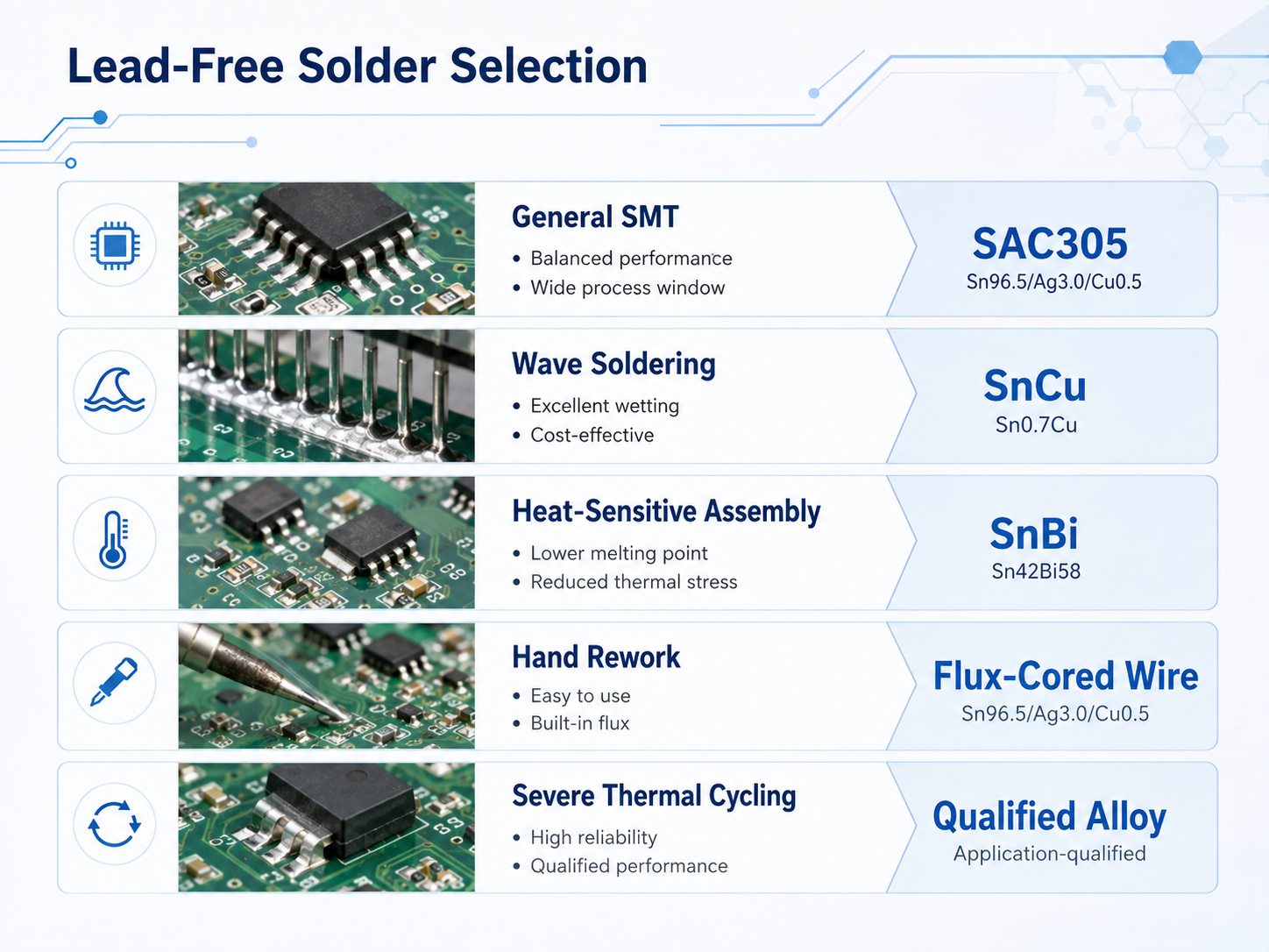
| Assembly Requirement | Typical Starting Point | Reason |
| General SMT reflow | SAC305 | Mature and widely supported process |
| Mixed SMT and through-hole PCBA | SAC305 or compatible SAC system | Easier alloy consistency |
| High-volume wave soldering | SnCu or low-Ag alloy | Lower silver cost |
| Heat-sensitive assembly | SnBi-based alloy | Lower process temperature |
| Hand soldering and rework | SAC or SnCu flux-cored wire | Practical manual application |
| Severe thermal cycling | Application-qualified alloy | Reliability must be validated |
| Legacy SnPb conversion | Process review required | Components and PCB may not tolerate lead-free conditions |
Low-temperature SnBi alloys can reduce thermal exposure, but mechanical requirements, alloy mixing, and rework conditions still need review.
At EBest Circuit, PCBA quotation and process review are easier when customers provide the BOM, PCB files, required solder alloy, compliance requirement, temperature limits, assembly method, and expected production volume.
What Standards Apply to Lead-Free Solder Materials?
Different standards apply to solder alloys, paste, flux, workmanship, and substance restrictions.
| Standard / Regulation | Main Relevance |
| IPC J-STD-006 | Electronic-grade solder alloys and solid solders |
| IPC J-STD-005 | Solder paste requirements |
| IPC J-STD-004 | Soldering flux classification and requirements |
| IPC J-STD-001 | Requirements for soldered electronic assemblies |
| EU RoHS | Restrictions on lead and other regulated substances |
RoHS compliance does not replace workmanship or process-control requirements.
The required standard revision should also be checked against the drawing, customer specification, or contract rather than assumed automatically.
What Reliability Issues Should Engineers Consider With Lead-Free Solder?
Lead-free solder reliability depends on the alloy, package, PCB construction, operating environment, and dominant failure mechanism.
Key issues include:
- Thermal cycling: repeated CTE mismatch strains solder joints.
- Intermetallic growth: interface layers continue to evolve during thermal exposure.
- Copper dissolution: relevant in prolonged wave and selective soldering.
- Voiding: important under QFNs, BTCs, power packages, and thermal pads.
- Drop and vibration loading: relevant to portable and mechanically stressed products.
- High operating temperature: increases the importance of creep and microstructural evolution.
- Mixed alloys: can change local composition, melting behavior, microstructure, and compliance status.
For reliability-sensitive projects, provide the expected operating temperature range, thermal-cycle requirement, vibration or drop conditions, major package types, board thickness, surface finish, and target product life.
What Are Acceleration Factors for Lead-Free Solder Materials?
Acceleration factors for lead free solder materials estimate how much faster solder-joint damage accumulates during an accelerated reliability test than under expected field conditions.
For thermal cycling, the result can be influenced by:
- temperature range
- maximum and minimum temperature
- dwell time
- ramp rate
- cycle frequency
- PCB and package geometry
- CTE mismatch
- solder-joint dimensions
- alloy creep and fatigue behavior
Coffin-Manson- and Norris-Landzberg-type models may be used for thermal-fatigue analysis, but the model assumptions and parameters should match the actual assembly.
Acceleration factors developed for SnPb joints or for one package type should not be transferred directly to another lead-free assembly without validation.
FAQs About Lead Free Solder Material
What is the most common lead-free solder for PCB assembly?
SAC305 is one of the most widely used general-purpose lead-free alloys. Its nominal composition is Sn96.5Ag3.0Cu0.5, with a melting range of approximately 217–220°C.
Is 60/40 solder lead free?
No. Traditional 60/40 solder contains approximately 60% tin and 40% lead.
Why does lead-free solder require a higher soldering temperature?
Common SAC and SnCu alloys melt at higher temperatures than Sn63Pb37. SAC305 melts around 217–220°C, compared with 183°C for Sn63Pb37.
Does lead-free solder need flux?
Yes. Flux helps remove surface oxides and improves solder wetting. The flux chemistry should match the soldering process and cleanliness requirements.
Can leaded and lead-free solder be mixed?
They can physically mix, but uncontrolled mixing can alter alloy composition, melting behavior, microstructure, process consistency, and regulatory compliance.
Is SAC305 suitable for wave soldering?
Yes. SAC305 can be used for wave soldering, although SnCu or lower-silver alloys may be considered for high-volume production where solder-pot cost matters.
Should a PCB drawing specify the exact solder alloy?
Yes, when the alloy is part of the approved process or reliability qualification. Otherwise, specify the required lead-free or RoHS status and applicable assembly standard.
How Can EBest Circuit Support Lead-Free PCB Assembly?
Lead-free solder selection should match the PCB assembly process, component temperature limits, reliability requirements, and compliance target. SAC305 is suitable for many assemblies, while SnCu, low-silver SAC, and SnBi alloys serve more specific process needs.
For a PCBA quotation, send your Gerber files, BOM, assembly drawings, production volume, required solder alloy, RoHS requirement, and any temperature or reliability constraints to EBest Circuit at sales@bestpcbs.com.