Absolute pressure sensors measure pressure from a fixed vacuum reference instead of comparing it with the changing atmosphere. That distinction makes them suitable for barometric measurement, altitude estimation, sealed systems, vacuum processes, and other applications where local weather or elevation must not redefine zero. A successful design depends on more than the sensing range. The reference type, pressure port, transfer function, temperature behavior, package stress, PCB layout, assembly process, and calibration method must all agree with the measurement task.
What Is an Absolute Pressure Sensor?
An absolute pressure sensor reports pressure relative to absolute zero pressure. Its zero reference is a sealed vacuum, not the air around the device. Pressure applied to the sensing side acts against that internal reference, allowing the output to represent the total pressure of the medium rather than the amount above or below the current atmosphere.
This reference point separates absolute sensing from gauge sensing. A gauge device uses local atmospheric pressure as its reference, so its zero follows weather and elevation. A differential device compares two accessible pressure ports. An absolute device normally has one process-pressure path and an internal sealed reference that the system cannot vent or reconnect.
The pressure value must include a clear reference notation. Common forms include kPa absolute, bar absolute, and psia. A bare value such as 100 kPa is incomplete when the context does not make the reference obvious. At normal atmospheric conditions, an absolute sensor may report close to atmospheric pressure while a vented gauge sensor reports close to zero. Both readings can be correct because they answer different questions.
How Do Absolute Pressure Sensors Work?
Pressure bends a diaphragm, and the sensor converts that deformation into an electrical result. A practical absolute sensor seals a high-vacuum cavity behind its sensing diaphragm. The process medium acts on the opposite side. The resulting mechanical strain changes resistance, capacitance, resonant frequency, or another measurable electrical property.
In a piezoresistive MEMS device, resistive elements placed in stressed regions of a silicon diaphragm form part of a bridge. Pressure changes the diaphragm strain and unbalances the bridge. An amplifier and compensation circuit then convert the small bridge signal into an analog voltage, current, or digital pressure code. Capacitive devices instead detect a change in spacing between the flexible diaphragm and a fixed electrode.
The conversion path usually contains several stages:
- Pressure input: The medium reaches the sensing diaphragm through a port, opening, or protective interface.
- Mechanical response: The diaphragm deflects according to the pressure difference between the process side and the sealed reference.
- Electrical conversion: A resistive, capacitive, or resonant element converts deflection into a raw signal.
- Signal conditioning: An ASIC amplifies, linearizes, and compensates the raw response for temperature and device variation.
- System output: The result appears as an analog voltage, a current signal, or a digital value over an interface such as I2C or SPI.
The sealed reference is stable, but the complete sensor is not automatically error-free. Diaphragm nonlinearity, bridge offset, package stress, temperature gradients, media compatibility, supply noise, and long-term drift can all move the reported value. Datasheet accuracy therefore needs to be read together with the conditions and error terms used to define it.
Absolute vs Gauge Pressure Sensors: What Is the Difference?
The difference is the reference pressure, not simply the package shape or output interface. Absolute pressure is referenced to vacuum. Gauge pressure is referenced to local atmosphere. Differential pressure is the difference between two applied pressures. Selecting the wrong reference can create a large systematic error even when the sensor is functioning normally.
The relationship between absolute and gauge pressure is:
Pabs = Pgauge + Patm
Here, Pabs is absolute pressure, Pgauge is pressure relative to the local atmosphere, and Patm is local atmospheric pressure. The equation is simple, but Patm is not constant. It changes with elevation and weather. A fixed conversion using a nominal atmospheric value is therefore unsuitable when the required uncertainty is smaller than those changes.
| Pressure Type | Reference | Typical Ports | Best Fit | Main Risk |
| Absolute | Sealed vacuum | One process input | Barometry, altitude, sealed vessels, vacuum processes | Using gauge limits or calibration assumptions |
| Gauge | Local atmosphere | One process input plus an atmospheric vent | Tires, open tanks, pumps, pneumatic lines | Blocked or contaminated vent path |
| Differential | Second applied pressure | Two pressure inputs | Filter drop, flow elements, room pressure | Overpressure on one side or reversed connections |
Absolute sensing is the correct choice when the value must remain tied to a fixed zero reference. Gauge sensing is often better when only pressure above the surrounding atmosphere matters. Differential sensing is required when the decision depends directly on the difference between two process points. Two separate absolute sensors can be subtracted in software, but their independent offset, temperature error, drift, and timing differences combine. That arrangement is not automatically equivalent to a differential sensor.
Which Technologies Do Absolute Pressure Sensors Use?
Piezoresistive and capacitive MEMS devices cover many embedded and industrial applications, but the best technology depends on range, stability, media, and bandwidth. The transduction method affects sensitivity, power, package construction, signal conditioning, temperature behavior, and suitability for static or dynamic measurements.
- Piezoresistive MEMS: Diaphragm strain changes implanted or deposited resistors. These devices can provide high sensitivity and compact integration, but bridge offset and temperature coefficients require compensation.
- Capacitive MEMS: Diaphragm movement changes capacitance. Low power and strong sensitivity are possible, although parasitic capacitance, contamination, and package stress require careful control.
- Resonant sensing: Pressure changes the frequency of a resonant structure. Frequency outputs can support excellent stability and resolution, but the construction and electronics are more complex.
- Strain-gauge metal diaphragms: Bonded or thin-film strain elements measure deformation of a metal structure. This approach is common where rugged packaging and media isolation are important.
- Specialized vacuum gauges: Pirani, ionization, and other vacuum technologies serve ranges where a conventional diaphragm sensor is no longer the best measurement method.
Piezoelectric sensing deserves a separate warning. It responds well to changing pressure and fast transients, but charge leakage makes many piezoelectric devices unsuitable for accurate static pressure measurement. A technology that performs well during a pressure pulse may not hold a stable DC reading.
Which Range, Accuracy, Resolution, and Response Time Matter?
Start with the real pressure envelope and required uncertainty, then check every datasheet term under the intended conditions. A wide range protects against overload but usually gives fewer output counts per unit of pressure. A narrow range improves usable sensitivity but may leave inadequate margin for startup surges, altitude changes, proof pressure, or fault conditions.
Important specifications include:
- Operating range: The interval over which the sensor is intended to report pressure. Confirm that the units and reference are absolute.
- Proof pressure: A temporary pressure that should not cause a permanent specification shift. It is not a normal operating target.
- Burst pressure: A structural limit associated with physical failure. It must never be treated as a usable measurement range.
- Total error: Determine whether the stated accuracy includes offset, span, nonlinearity, hysteresis, temperature, and long-term drift or only a subset.
- Resolution: The smallest output step does not guarantee equal measurement accuracy. Noise and systematic error can be much larger than one code.
- Response time: Port volume, tubing, digital filtering, output data rate, and sensor bandwidth can all limit the response.
- Media compatibility: Gas, liquid, condensation, corrosive vapor, and particulates can require a different port, gel, diaphragm material, or isolation method.
Ratiometric analog sensors also tie their output scale to supply voltage. If the analog-to-digital converter uses the same supply as its reference, supply movement can cancel in the ratio. If it uses a different reference, supply tolerance becomes a measurement error unless the design measures or regulates that supply.
How Should Analog and Digital Absolute Pressure Sensor Outputs Be Read?
The electrical interface must preserve the sensor transfer function without adding supply, timing, or conversion error. Analog outputs require a valid ADC range, reference strategy, source impedance, filtering, and fault limits. Digital outputs require correct logic levels, bus timing, pull-up values, command sequencing, status handling, and pressure-code conversion.
For a linear analog sensor, pressure can often be calculated from a datasheet transfer function of the form:
P = (Vout – Voffset) / Sensitivity
Voffset and Sensitivity must come from the selected part and operating conditions. Some sensors specify normalized output as a fraction of supply rather than fixed volts. Firmware must also reject readings outside the valid electrical range and distinguish a real pressure extreme from an open circuit, short circuit, startup state, or saturated ADC.
Digital sensors commonly return a raw pressure code plus temperature and status information. The conversion may use calibration coefficients stored inside the device. Read the complete transaction defined in the datasheet. Mixing byte order, signed and unsigned arithmetic, pressure units, or compensation timing can produce a plausible but wrong result. A repeated I2C address also matters when several identical sensors share one bus.
The analog input vs digital input choice affects fault detection, wiring, conversion, and test coverage. Digital output reduces sensitivity to analog routing noise after conversion, but it does not remove pressure-port, thermal, package-stress, calibration, or media errors.
How Should Absolute Pressure Sensors Be Integrated on a PCB?
Place the sensor where pressure can reach the port cleanly while heat, board strain, contamination, and electrical noise remain controlled. The package is both a mechanical measuring element and an electronic component. A layout that is electrically correct can still shift readings if the PCB bends the package or conducts heat from a regulator into the sensor.
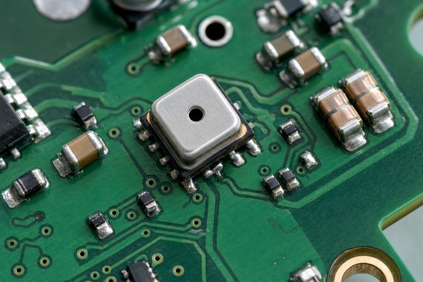
- Pressure access: Keep the port opening clear. Align enclosure holes, gaskets, manifolds, and tubing without side loading the package.
- Thermal isolation: Separate the sensor from regulators, processors, power resistors, and airflow that creates rapid local temperature changes. Board slots may help when the selected manufacturer recommends them.
- Mechanical isolation: Avoid mounting holes, snap fits, connectors, and depaneling tabs that bend the PCB near the package.
- Local decoupling: Place the specified bypass capacitor close to the supply pins with a short return path.
- Interface routing: Keep analog traces away from switching nodes. Size I2C pull-ups for bus capacitance, voltage, and timing instead of copying a default value.
- Contamination control: Prevent flux, cleaning liquid, conformal coating, adhesive, dust, and condensation from entering the port.
- Test access: Provide accessible supply, ground, bus, interrupt, and analog nodes so electrical faults can be separated from pressure faults.
Package land patterns, solder-paste apertures, reflow limits, and handling rules must follow the exact component documentation. Pressure packages may include open cavities, gels, membranes, or delicate ports. Vacuum pickup position and cleaning methods that are harmless for a sealed IC can damage or contaminate a sensor.
Which PCB Layout and Assembly Errors Distort Pressure Readings?
Temperature gradients, board stress, port blockage, and power noise are common causes of readings that look like sensor drift. These errors can pass a basic communication test because the component remains electrically alive. Validation must therefore compare pressure output with physical conditions and assembly state.
| Error | Observed Behavior | Verification | Corrective Action |
| Heat source nearby | Warm-up drift or load-dependent offset | Compare readings before and after local heating | Increase spacing, reduce heat flow, or add approved isolation slots |
| PCB bending | Offset changes with screws, enclosure pressure, or handling | Measure before and after assembly torque | Move the sensor or change mechanical support |
| Blocked port | Slow response, trapped pressure, or fixed reading | Inspect the opening and apply controlled pressure steps | Revise coating, cleaning, gasket, or enclosure process |
| Supply ripple | Periodic noise correlated with switching activity | Probe supply and output at the same time | Improve decoupling, routing, filtering, or regulation |
| Incorrect conversion | Stable but scaled or offset result | Compare raw codes with the datasheet transfer function | Correct units, coefficients, byte order, or ADC reference |
| Moisture or residue | Intermittent drift, slow recovery, or leakage | Inspect under magnification and repeat after controlled drying | Improve cleaning, drying, venting, and protection |
Panel separation is another risk. Router or breakaway stress can shift package offset after calibration if the sensor sits near a tab. If a board-level offset is stored before depaneling or final enclosure assembly, the stored correction may no longer represent the finished unit.
Where Are Absolute Pressure Sensors Used?
Absolute sensing is used when the result must be independent of the changing atmospheric reference. The same reference principle serves many products, but pressure range, media, bandwidth, environmental protection, and required uncertainty differ widely.
- Barometric measurement: Atmospheric pressure is measured against vacuum for weather observation and environmental compensation.
- Altitude estimation: Changes in atmospheric pressure support altitude or vertical-motion calculations in portable, aviation, and navigation systems.
- Vacuum processes: Sealed chambers, packaging equipment, pumps, and laboratory systems need pressure referenced to true zero.
- Engine management: A manifold absolute pressure sensor measures intake pressure so control logic can estimate operating load with other inputs.
- Sealed vessels: Absolute readings help when the surrounding atmosphere must not redefine the process value.
- Medical and analytical equipment: Controlled gas paths may require compact absolute measurement with documented media and cleaning compatibility.
An application label alone is not enough for selection. A barometric part optimized for clean dry air may not tolerate liquid, corrosive vapor, pressure pulsation, or aggressive cleaning. A rugged industrial transducer may not meet the power, size, or digital-interface needs of a compact embedded board.
How Are Absolute Pressure Sensors Calibrated?
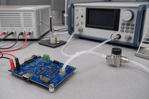
Calibration compares the complete measurement channel with a traceable absolute-pressure reference at defined pressure and temperature points. A single atmospheric reading cannot prove full-range accuracy. The procedure must control leaks, stabilization time, reference uncertainty, pressure direction, temperature, supply, orientation when relevant, and the exact conversion used by the system.
- Confirm that the reference instrument and pressure source cover the required absolute range with suitable uncertainty.
- Connect the sensor with clean, leak-tight tubing and minimize trapped volume when response time matters.
- Power the complete board under its normal supply and allow the specified warm-up and thermal stabilization time.
- Apply several increasing pressure points across the working range and record raw output, converted pressure, reference pressure, temperature, and status.
- Apply decreasing points to reveal hysteresis, leaks, mechanical effects, or slow pneumatic response.
- Repeat at required temperatures when the application uncertainty includes more than room-temperature operation.
- Calculate offset, span, linearity, repeatability, and total error using the same rules defined for acceptance.
- Store correction coefficients only when the sensor documentation and system architecture support field or board-level calibration.
Zero calibration requires care because a true zero absolute reference is a high-quality vacuum, not an open port. Some devices are calibrated at nonzero points and extrapolated according to their specified transfer function. Never force a zero adjustment at atmospheric pressure on an absolute sensor. That would redefine the output as if atmosphere were zero and destroy the intended reference.
How Should Absolute Pressure Sensors Be Tested and Troubleshot?
Separate electrical communication, pressure delivery, thermal behavior, and calibration before replacing the sensor. A wrong reading can come from a blocked port, leaking tube, incorrect reference type, conversion bug, unstable supply, assembly stress, or damaged device. Random replacement hides the failure mechanism and can leave the same system error in place.
- Check identity and status: Read the device ID, status bits, and raw output before applying software correction.
- Verify supply integrity: Measure voltage and ripple at the sensor pins during the failing condition.
- Inspect the pressure path: Look for coating, residue, pinched tubing, leaks, gasket misalignment, and trapped liquid.
- Apply known steps: Use at least two controlled absolute-pressure points to distinguish a fixed offset from a dead or saturated response.
- Compare raw and converted data: Confirm byte order, signed arithmetic, coefficients, units, ADC reference, and ratiometric assumptions.
- Test temperature influence: Observe warm-up and controlled temperature changes without touching or bending the board.
- Check assembly stress: Compare the bare PCB, secured assembly, and fully closed enclosure using the same pressure.
- Review drift evidence: Use time-stamped reference measurements instead of judging drift from unrelated field conditions.
Production validation should include both electrical and pneumatic coverage. An automated test can confirm communication and plausible ambient output, but that does not prove sensitivity across the range. A controlled pressure point or leak-tested pneumatic fixture provides stronger coverage. The acceptance limits must include reference uncertainty and stabilization behavior so good units are not rejected by the fixture itself.
FAQs About Absolute Pressure Sensors
Q1: What does an absolute pressure sensor measure?
A1: It measures pressure relative to absolute zero pressure, using a sealed vacuum reference. The reading therefore includes atmospheric pressure when the sensing port is exposed to air.
Q2: Why does an absolute sensor show about atmospheric pressure in open air?
A2: Open air is not zero absolute pressure. The sensor compares air with its vacuum reference, so a value near local barometric pressure is expected.
Q3: Can absolute pressure be negative?
A3: A true absolute pressure cannot be below zero. A negative displayed result indicates conversion, offset, calibration, or reference errors, not a physical pressure below perfect vacuum.
Q4: Can an absolute pressure sensor replace a gauge sensor?
A4: Not without accounting for atmospheric pressure. The two devices use different zero references, so identical numeric ranges do not make them interchangeable.
Q5: What is a barometric absolute pressure sensor?
A5: It is an absolute sensor optimized for the atmospheric range. Its fixed vacuum reference allows barometric pressure and altitude-related changes to be measured.
Q6: Does an absolute pressure sensor need a vent?
A6: It needs a path for the process pressure to reach the sensing side, but its reference side is sealed against vacuum rather than vented to atmosphere.
Q7: Can two absolute sensors measure differential pressure?
A7: Their readings can be subtracted, but combined offset, drift, timing, and temperature errors may exceed those of one purpose-built differential sensor.
Q8: What output interfaces are available?
A8: Common choices include ratiometric voltage, conditioned voltage, current, I2C, and SPI. The correct option depends on distance, noise, power, conversion, and diagnostic needs.
Q9: How often should an absolute pressure sensor be calibrated?
A9: The interval depends on required uncertainty, drift, environment, duty cycle, and quality history. Set it from documented stability and reference checks, not a universal schedule.
Q10: What causes a slow absolute pressure response?
A10: Restricted ports, long narrow tubing, trapped volume, filters, condensation, leaks, or digital averaging can slow the result. Test the pneumatic path and software filter separately.
For support with a PCB that integrates absolute pressure sensors, contact EBest Circuit at sales@bestpcbs.com and provide Gerber or ODB++, BOM, quantity, stackup, assembly, programming, pressure-interface, and test requirements.