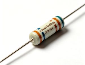
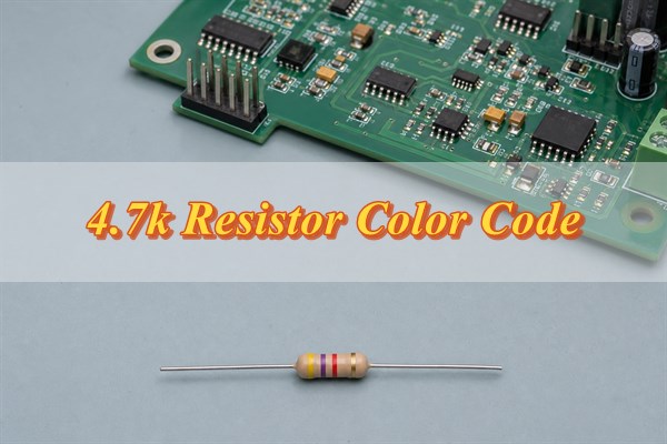
The standard four-band 4.7k resistor color code is yellow-violet-red-gold. Yellow represents 4, violet represents 7, red supplies the ×100 multiplier, and gold specifies ±5% tolerance. The result is 47 × 100 = 4,700Ω, which is also written as 4.7kΩ or 4k7.
Visual decoding is only the first verification step. Band direction, tolerance, heat discoloration, conformal coating, similar resistance values and parallel PCB paths can all affect the decision. Confirm the value against the schematic and BOM, remove power, discharge stored energy and isolate one resistor lead when an in circuit measurement is inconclusive.
What Is the Correct 4.7k Resistor Color Code?
A common four-band 4.7kΩ ±5% resistor uses yellow, violet, red and gold. The first two bands are the significant digits, the third is the multiplier and the fourth is the tolerance. Reading the colors in the wrong direction or confusing red with orange changes the decoded value by a factor of ten.
| Band | Color | Meaning | Result |
| 1 | Yellow | First digit | 4 |
| 2 | Violet | Second digit | 7 |
| 3 | Red | Multiplier | ×100 |
| 4 | Gold | Tolerance | ±5% |
The nominal resistance is calculated before tolerance is applied. Yellow and violet form 47; red multiplies 47 by 100 to produce 4,700Ω. Gold does not change the nominal value. It defines how far a new resistor may deviate from 4,700Ω under the specified measurement conditions.
Not every 4.7kΩ resistor ends with a gold band. Brown commonly indicates ±1%, red ±2% and silver ±10%. The tolerance band must therefore be decoded separately from the value bands. Package size, power rating and resistor technology cannot be determined from the four value and tolerance colors alone.
Color decoding also cannot distinguish a carbon film part from a metal film or flameproof resistor with complete certainty. Body color and surface finish vary by manufacturer. When noise, pulse loading, safety behavior or long term drift matters, use the full manufacturer part number rather than treating the band sequence as a complete specification.
How Should You Determine the Correct Reading Direction for a 4.7k Resistor Color Code?
Begin at the end where the significant digit bands are grouped more closely together. On many four-band axial resistors, the gold or silver tolerance band is separated by a wider gap and belongs on the right. Five- and six-band parts require more care because both end bands may use ordinary colors.
- Inspect the spacing. Look for a wider gap before the final tolerance or temperature-coefficient band.
- Check the end color. Gold and silver are normally tolerance colors and do not serve as significant digits.
- Decode both directions. Compare the resulting values and reject an orientation that produces an invalid or implausible band role.
- Compare the circuit record. Match the result with the reference designator, schematic function, BOM value and approved part number.
- Measure when uncertain. Use resistance mode on an unpowered circuit and isolate the component if connected paths affect the result.
Use neutral white lighting and magnification when the colors are unclear. Heat can darken a resistor body, flux residue can add a yellow-brown tint, and conformal coating can create reflections. Do not scrape the coating or damage the resistor merely to improve the view; electrical verification is safer when visual evidence remains ambiguous.
| Observation | Likely Meaning | Next Check |
| Gold or silver band isolated at one end | That end is normally the tolerance side | Read from the opposite end |
| Both directions produce plausible values | Visual direction remains uncertain | Compare BOM, schematic and measurement |
| Band colors change with viewing angle | Coating reflection or poor lighting | Use neutral light and magnification |
| Body or bands are darkened by heat | Value and condition cannot be trusted visually | Inspect the circuit and isolate the part |
How Do 4‑Band, 5‑Band and 6‑Band Color Codes Represent 4.7kΩ?
Four band codes use two significant digits, while five and six band codes normally use three. A five band 4.7kΩ resistor is decoded as 470 × 10. A sixth band usually adds temperature coefficient information rather than another resistance digit.
| Format | Typical Sequence | Calculation | Final Band Role |
| 4-band | Yellow, violet, red, gold | 47 × 100 = 4,700Ω | Gold: ±5% |
| 5-band | Yellow, violet, black, brown, brown | 470 × 10 = 4,700Ω | Brown: ±1% |
| 6-band | 5-band value plus TCR band | 470 × 10 = 4,700Ω | Temperature coefficient |
The common five band ±1% sequence is yellow, violet, black, brown and brown. Yellow, violet and black form 470; the first brown band multiplies by 10; the last brown band specifies ±1%. The physical spacing between the multiplier and tolerance bands helps distinguish their roles.
A six band part can add temperature coefficient in parts per million per degree Celsius. That parameter matters in precision dividers, measurement circuits and bias networks that operate across a wide temperature range. Confirm the exact sixth band meaning in the component documentation because the band count does not prove pulse capability, working voltage or long term stability.
A sixth band does not automatically make the component more accurate. A six band resistor can have a wider initial tolerance than another five band part, while providing additional temperature information. Compare the tolerance band, TCR band and datasheet together instead of ranking components by band count.
What Does IEC 60062 Specify About 4.7k Resistor Color Codes?
IEC 60062:2016 with Amendment 1:2019 specifies designation and marking codes for resistor values, tolerances and temperature coefficients. It covers color coding and letter-and-digit forms used to communicate resistance values. The standard explains the marking system; it does not certify that a particular resistor meets every electrical or reliability requirement.
Under the color-code method, each color has a defined digit or multiplier role. IEC 60062 also supports resistance notations that replace a decimal point with a multiplier letter. This makes 4k7 easier to read than a small printed decimal in many schematics and BOMs. Fixed-length numerical markings can express resistance values on suitable components.
IEC 60062 does not establish the actual power rating, maximum working voltage, pulse endurance or operating temperature limit of an unidentified resistor. Those parameters come from the applicable component specification and manufacturer datasheet. IEC 60115‑1:2020 supplies generic terms, inspection procedures and test methods for fixed resistors, but the relevant sectional or detail specification still controls acceptance.
Assembly requirements have a separate purpose. IPC J‑STD‑001J addresses soldering materials and process requirements, while IPC‑A‑610J addresses completed assembly acceptability. Neither proves that a visually correct resistor is electrically 4.7kΩ. BOM control, material identity and an appropriate electrical or functional test are still required.
IEC 60063:2015 has a related but different role: it defines preferred number series for resistors and capacitors. The presence of 4.7 in a preferred series explains the widespread nominal value, but it does not prove the tolerance or condition of an installed component. Marking, preferred value and component performance remain separate acceptance questions.
For production records, identify the standard by revision instead of writing only “per IEC” or “per IPC.” Also record the approved manufacturer part number and datasheet revision. Add any customer specific acceptance criteria separately. This prevents a marking standard from being misused as evidence for power, reliability or assembly quality.
What Resistance Range Does Each 4.7k Resistor Tolerance Allow?
Tolerance converts the nominal 4,700Ω value into an allowable resistance interval. Multiply 4,700Ω by the tolerance percentage, then subtract and add that deviation. Meter accuracy, lead contact, temperature and the component’s specified test conditions must be considered before accepting or rejecting a measured value.
| Tolerance | Band | Minimum | Maximum | Typical Decision Use |
| ±10% | Silver | 4,230Ω | 5,170Ω | Noncritical legacy or general purpose circuits |
| ±5% | Gold | 4,465Ω | 4,935Ω | General pullups and nonprecision networks |
| ±2% | Red | 4,606Ω | 4,794Ω | Moderate accuracy requirements |
| ±1% | Brown | 4,653Ω | 4,747Ω | Precision bias or divider networks |
| ±0.5% | Green | 4,676.5Ω | 4,723.5Ω | Tighter measurement and control circuits |
For example, ±5% of 4,700Ω is 235Ω, so the allowed interval is 4,465Ω to 4,935Ω. A reading of 4.82kΩ can pass a ±5% requirement but fail a ±1% requirement. The BOM and tolerance band must therefore be known before the same measured value is judged acceptable.
Tolerance is not the same as temperature coefficient or aging stability. A resistor can begin inside its room temperature tolerance and move with temperature or long term stress. For accuracy-sensitive circuits, check initial tolerance, TCR, environmental range, load life performance and any ratio matching requirement together.
Measurement uncertainty must be applied to the instrument result, not ignored after the tolerance calculation. If a meter specifies accuracy as a percentage of reading plus a number of display counts, both terms affect a borderline result. Clean probe contact and a stable temperature are also necessary before a component near the limit is rejected.
How Can You Distinguish a 4.7k Resistor Color Code from 470Ω and 47kΩ?
The multiplier band separates 470Ω, 4.7kΩ and 47kΩ. All three values begin with the digits 4 and 7, but brown multiplies by 10, red by 100 and orange by 1,000. One multiplier-color error changes resistance by a factor of ten.
| Resistance | Value Bands | Multiplier | SMD Code |
| 470Ω | Yellow, violet, brown | ×10 | 471 |
| 4.7kΩ | Yellow, violet, red | ×100 | 472 |
| 47kΩ | Yellow, violet, orange | ×1,000 | 473 |
Red and orange are easily confused under warm light or a tinted coating. Compare the resistor with a neutral color reference, then use a resistance measurement if the decade remains uncertain. An isolated reading near 470Ω, 4.7kΩ or 47kΩ normally separates these values clearly.
An assembled board requires additional caution because a parallel path can pull a 4.7kΩ reading below its tolerance range. A low in circuit result does not automatically identify a 470Ω part. Review the schematic and lift one terminal before deciding that the wrong decade was assembled.
The electrical consequence of a decade error depends on the circuit. With a 3.3V open-drain line held low, ideal pull-up currents are about 7.02mA for 470Ω, 0.702mA for 4.7kΩ and 0.0702mA for 47kΩ. The wrong value can therefore overload a driver or create an excessively slow rising edge.
Bus capacitance makes the difference visible in timing. With a simplified 200pF RC load, the time constant is 94ns for 470Ω, 940ns for 4.7kΩ and 9.4µs for 47kΩ. For I²C, the 30%–70% rise time is approximately 0.8473 × RP × CB, so selection must also satisfy the bus mode rise time limit and the device’s low level sink current limit.
How Do 4k7, 4700Ω, 472 and 4701 Represent a 4.7k Resistor?
All four forms can represent the nominal value 4,700Ω. The formats serve different records and component types. Schematics and BOMs commonly use 4k7, while 4700Ω states the full value. Suitable SMD packages may carry the top marking 472 or 4701.
| Marking | Calculation | Common Context | Limitation |
| 4k7 | 4.7kΩ | Schematic or BOM | Does not state tolerance by itself |
| 4700Ω | 4,700Ω | Datasheet or test record | Requires a separate rating specification |
| 472 | 47 × 10² | Three digit SMD code | Small packages may be unmarked |
| 4701 | 470 × 10¹ | Four-digit SMD code | Does not prove power or technology |
The letter in 4k7 replaces the decimal point, reducing the risk that a faint dot will be missed. In the three-digit SMD code 472, the first two digits are 47 and the final digit indicates two zeros. In 4701, the first three digits are 470 and the last digit applies a ×10 multiplier.
Do not infer an unmarked SMD resistor value from its pad size or location. Confirm the reference designator, approved BOM, reel label, feeder setup and placement record. Use electrical measurement or functional test when production evidence does not resolve the identity.
During purchasing, keep the engineering value and the orderable part number in separate BOM fields. The engineering value may read 4k7, while the manufacturer part number defines package, tolerance, power, TCR and termination. Converting every field to “472” can remove information and increase substitution risk.
Why Can a 4.7k Resistor Show an Incorrect Reading on a PCB?
A meter connected across an installed resistor measures every conductive path between its probes, not only the resistor body. Parallel resistors, IC inputs, protection devices, semiconductor junctions and connected modules can reduce or destabilize the displayed value. Capacitors can create a changing reading as the meter’s test current charges them.
- Parallel resistance: another path between the same nodes makes the measured value lower than the isolated resistor.
- Semiconductor conduction: meter polarity and test voltage can forward bias a junction and alter the result.
- Stored charge: capacitors can create drift and may leave unsafe residual voltage on the assembly.
- Probe contact: oxidation, flux, coating or unstable pressure can produce intermittent or high readings.
- Wrong test state: an energized board can damage the meter or assembly when resistance mode is used.
- Damaged interconnect: a cracked lead, lifted pad or broken trace can imitate an open resistor.
A lower than expected in circuit reading is common because parallel paths reduce total resistance. A reading above the allowed range is more suspicious, but it still requires contact and interconnect checks. Reverse the probes when semiconductor paths are suspected and compare the result with the schematic before isolating the component.
A simple parallel path shows the scale of the error. A correct 4.7kΩ resistor in parallel with 10kΩ produces approximately 3.20kΩ at the same two nodes. That reading is predictable from the circuit and does not indicate that the 4.7kΩ component has changed value.
A drifting display often indicates capacitance rather than an unstable resistor. The meter injects a small test current, causing the capacitor voltage and displayed resistance to change. Disconnect power, discharge the capacitor safely and wait for the reading to settle before deciding whether component isolation is necessary.
An open display can come from a failed resistor, but it can also result from a cracked lead, damaged via, lifted pad or poor probe contact. Probe directly on the resistor leads when accessible, then compare that result with pad to pad and trace measurements. The difference identifies whether the failure is inside the component or in the interconnect.
How Should You Test a 4.7k Resistor In‑Circuit and Out‑of‑Circuit?
Screen the resistor on the unpowered PCB, then lift one lead only when connected paths prevent a reliable decision. Power must be removed and stored charge discharged before resistance testing, as specified in Fluke’s resistance measurement procedure.
- Make the board safe. Disconnect power, batteries, programmers and powered cables. Confirm zero voltage at the test nodes and discharge relevant capacitors.
- Identify and inspect the part. Match the reference designator to the schematic and BOM. Check the body, leads, solder joints, pads and nearby components for damage or contamination.
- Measure in circuit. Select resistance mode or autorange, contact both resistor terminals and avoid adjacent pads. Record a stable, low, high, open, drifting or polarity-dependent result.
- Account for connected paths. Compare the reading with parallel resistors, IC inputs, protection devices and capacitors shown on the schematic. A low or changing value may be a network effect.
- Isolate only when necessary. Lift one lead with a controlled rework process if the circuit prevents a clear conclusion. Do not cut a lead or overheat the pad for convenience.
- Measure the isolated resistor. Allow the part to cool, clean the contact points and compare the stable reading with the specified tolerance range and meter uncertainty.
- Restore and verify the assembly. Resolder the lead, inspect wetting and pad condition, then repeat the resistance check and the circuit function affected by the resistor.
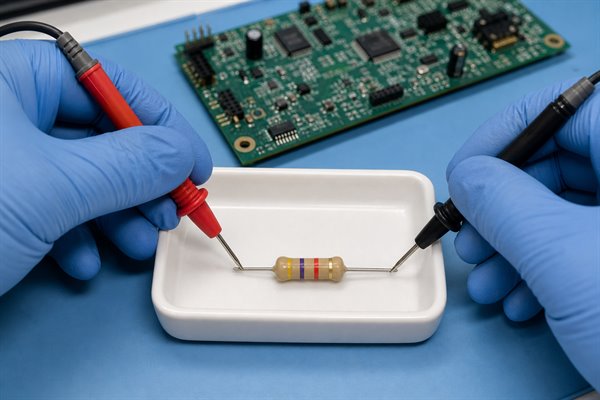
An isolated ±5% part should read 4.465kΩ to 4.935kΩ; an isolated ±1% part should read 4.653kΩ to 4.747kΩ. Apply the BOM tolerance and the meter’s uncertainty before accepting a borderline value.
Continuity mode is not a resistance-value test. Its threshold varies by meter, so a beep or silence cannot establish 4.7kΩ, tolerance or component condition.
What Evidence Confirms Whether a 4.7k Resistor Passes or Fails?
A pass decision requires a stable isolated value within the specified tolerance, valid material records and a successful circuit level check. An in circuit reading alone is screening evidence because the meter may include other conductive paths.
| Observed Result | Likely Explanation | Required Action |
| Stable value inside the isolated tolerance range | Resistor value is consistent with its marking | Restore the joint and perform the circuit test |
| Stable low value only in circuit | Parallel network path | Calculate the network or lift one lead |
| Reading rises or falls | Capacitor charging or semiconductor behavior | Discharge, reverse probes and review the schematic |
| Open at pads but correct on resistor leads | Joint, pad, via or trace failure | Inspect and repair the interconnect |
| Stable isolated value outside tolerance | Wrong value, damage or excessive drift | Verify part identity and replace with an approved part |
Four-wire measurement is rarely necessary at 4.7kΩ because test-lead resistance is small relative to the component value. For formal acceptance, record the meter model, calibration status, range, stated accuracy, measured value and test temperature.

For production, the approved BOM and reel label establish material identity; placement records and AOI verify location and visible markings; ICT, flying-probe or functional testing supplies electrical evidence. Test limits must account for parallel paths, and functional coverage must exercise the affected pull-up, bias, divider or timing node.
FAQs About 4.7k Resistor Color Codes
Q1: Does a 4.7kΩ resistor have polarity?
A1: A standard fixed resistor is nonpolarized. Either lead may face either circuit node, although consistent band orientation improves inspection and manual identification.
Q2: Can two series resistors replace one 4.7kΩ resistor?
A2: Series values may total 4.7kΩ, but the substitution requires engineering approval. Combined tolerance, voltage distribution, power dissipation, footprint, creepage and added solder joints can change reliability.
Q3: Can parallel resistors be used to obtain 4.7kΩ?
A3: Yes, if the calculated parallel value and worst-case tolerance meet the circuit requirement. Verify each resistor’s power, the combined footprint and failure behavior before changing the BOM.
Q4: Can a potentiometer adjusted to 4.7kΩ replace a fixed resistor?
A4: Only when adjustability, wiper failure and drift are acceptable. A potentiometer adds mechanical variability, a different footprint and a possible open wiper failure mode that a fixed resistor does not have.
Q5: Can an SMD resistor replace an axial 4.7kΩ resistor?
A5: Only after electrical, thermal and mechanical review. The replacement must satisfy resistance, tolerance, voltage, pulse energy, power derating, land pattern and rework requirements.
Q6: How can a color-blind technician identify the bands?
A6: Use a calibrated color-identification aid and confirm the value electrically. A BOM, reference designator and isolated resistance measurement are more reliable than unaided color judgment.
Q7: Can an axial 4.7kΩ resistor be mounted vertically?
A7: Yes, when the approved footprint and assembly requirements permit it. Check component height, lead forming radius, mechanical support, electrical clearance and vibration exposure.
Q8: Can a resistor pass an ohmmeter test but fail during operation?
A8: Yes, a room-temperature resistance check does not test every stress. Pulse overload, excessive working voltage, intermittent leads, thermal drift or moisture damage may appear only under operating conditions.
Q9: Can 4.7kΩ be used as an LED current-limiting resistor?
A9: It can, but the resulting current must be calculated. Use supply voltage minus LED forward voltage, divide by 4.7kΩ, then verify brightness and resistor power across tolerances.
Q10: Can a color-banded component be an inductor instead of a resistor?
A10: Yes, some axial inductors also use color bands. Confirm the reference designator, schematic symbol and impedance behavior instead of identifying the component by appearance alone.
Conclusion
The four-band 4.7k resistor color code is yellow, violet, red and gold for a common ±5% part. A reliable PCB decision also requires the correct reading direction, band format, tolerance range, schematic, BOM and measurement state. When connected circuitry changes the reading, isolate one terminal before rejecting or replacing the resistor.
For a PCB or PCBA quotation, send your Gerber or ODB++, BOM, quantity, stackup, assembly details, programming method and test requirements to sales@bestpcbs.com. EBest Circuit will review the manufacturing package and identify component-control, assembly or test details that require confirmation before production.