What Is a 104 Ceramic Capacitor?
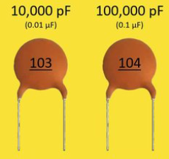
A 104 ceramic capacitor is a ceramic capacitor marked with the code “104,” which means its capacitance value is 0.1uF, also written as 100nF or 100,000pF.
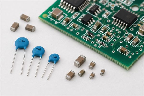
In PCB and PCBA projects, this capacitor is commonly used for decoupling, bypassing, filtering, and noise reduction. However, the marking “104” only tells the capacitance value. It does not define the voltage rating, dielectric material, tolerance, package size, or reliability grade.
What is the value of 104 on a ceramic capacitor?
The value of 104 on a ceramic capacitor is 100,000pF, which equals 100nF or 0.1uF.
| Marking | Value in pF | Value in nF | Value in uF |
| 104 | 100,000pF | 100nF | 0.1uF |
A common mistake is reading “104” as 104pF. That is incorrect. Under the standard three-digit capacitor code system, 104 means 10 followed by 4 zeros in picofarads.
How to Read the 104 Capacitor Code?
The three-digit capacitor code uses the first two digits as significant numbers and the third digit as the number of zeros in picofarads.
For 104:
| Code Part | Meaning |
| 10 | First two significant digits |
| 4 | Add four zeros |
| Result | 100,000pF |
| Converted value | 100nF or 0.1uF |
This rule also applies to many other capacitor codes.
| Code | Value |
| 101 | 100pF |
| 102 | 1,000pF / 1nF |
| 103 | 10,000pF / 10nF |
| 104 | 100,000pF / 100nF / 0.1uF |
| 105 | 1,000,000pF / 1uF |
For PCBA sourcing, this code should not be used alone in the BOM. A complete specification should also include voltage rating, dielectric, tolerance, package, and preferred manufacturer or approved alternatives.
How to test ceramic capacitor 104?
A 104 ceramic capacitor can be tested with a capacitance meter, LCR meter, or a multimeter that supports capacitance measurement. The expected reading should be close to 0.1uF, depending on tolerance and test conditions.
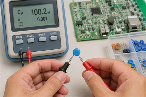
Practical testing steps:
- Remove power from the circuit.
- Discharge the capacitor safely.
- If possible, test the capacitor out of circuit for a more accurate reading.
- Set the meter to capacitance mode.
- Measure across the two terminals or pads.
- Compare the reading with the expected value and tolerance.
In-circuit testing can be misleading because other components may be connected in parallel. If the reading is abnormal, remove one side of the capacitor or test a spare part with the same specification before deciding it has failed. If the capacitor is shorted, a multimeter may show very low resistance or continuity where it should not.
A normal 104 ceramic capacitor may not read exactly 0.100uF. For example, a ±10% part may read roughly between 0.09uF and 0.11uF under proper test conditions. Class 2 ceramic capacitors such as X7R, X5R, Y5V, or Z5U can also vary with voltage, temperature, aging, and measurement method.
Is a 104 Ceramic Capacitor Polarized?
A standard ceramic capacitor 104 is usually not polarized. It can normally be installed in either direction.
This is different from electrolytic or tantalum capacitors, which often have positive and negative terminals. For PCB assembly, polarity is usually not a concern for a ceramic disc capacitor 104 or an MLCC 104 capacitor, but package orientation may still matter for automated placement, layout consistency, or inspection.
Are all 104 capacitors the same?
No. All 104 capacitors have the same nominal capacitance value, but they are not the same component.
| Specification | Why It Matters |
| Voltage rating | A 16V, 25V, 50V, 100V, or 1kV part may be used in very different circuits |
| Dielectric | X7R, X5R, Y5V, Z5U, and C0G/NP0 have different stability and cost |
| Package | Disc, radial leaded, 0603, 0805, 1206, and other MLCC sizes affect assembly |
| Tolerance | Common values include ±5%, ±10%, and ±20% |
| Temperature rating | Important for automotive, industrial, and outdoor electronics |
| DC bias behavior | Some ceramic capacitors lose effective capacitance under applied DC voltage |
There is no default 104 ceramic capacitor voltage rating. The same 0.1uF value may be sold as 16V, 25V, 50V, 100V, 1kV, or higher. Replacing a 50V 104 capacitor with a 16V part in a higher-voltage circuit can create reliability or safety risk.
Common Uses of 104 Ceramic Capacitors in PCB Design
A 104 ceramic capacitor is commonly used where a small, low-cost, non-polarized capacitor is needed for noise control, local energy storage, or signal conditioning.
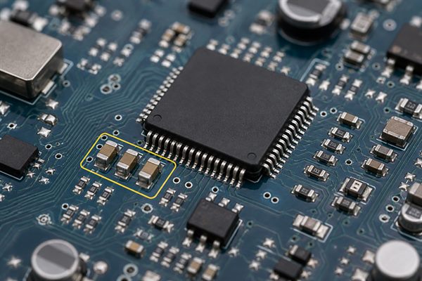
Common PCB uses include:
- IC power pin decoupling
- Bypass capacitor near microcontrollers, logic ICs, and sensors
- High-frequency noise filtering
- Signal coupling in low-power circuits
- RC timing or filtering circuits
- Power rail stabilization with other capacitor values
- EMI noise reduction in simple circuits
For decoupling, placement matters. A 104 capacitor should usually be placed close to the IC power and ground pins, with short traces and a low-inductance return path. If it is placed far away from the IC, the same capacitor value may not provide the expected high-frequency noise suppression.
For timing, analog filtering, audio, RF, or precision circuits, the dielectric and tolerance matter more than the printed 104 code. A random Y5V 104 capacitor may not behave like an X7R or C0G part in the same circuit.
104 Ceramic Capacitor vs 0.1uF, 100nF, and Other Codes
A 104 ceramic capacitor, a 0.1uF ceramic capacitor, and a 100nF ceramic capacitor usually refer to the same capacitance value. The difference is only the way the value is written.
| Expression | Meaning | Common Use |
| 104 ceramic capacitor | Marking code on the component or BOM | Common in repair, basic sourcing, and component identification |
| 0.1uF ceramic capacitor | Capacitance in microfarads | Common in schematics and datasheets |
| 100nF ceramic capacitor | Capacitance in nanofarads | Common in engineering discussions |
| 100,000pF ceramic capacitor | Capacitance in picofarads | Useful for understanding the code calculation |
The practical takeaway is simple: 104 = 0.1uF = 100nF = 100,000pF. But the full part number still depends on voltage rating, dielectric, package, and tolerance.
How to Choose the Right 104 Ceramic Capacitor for PCBA?
Choosing the right 104 ceramic capacitor for PCBA means matching the capacitor to the circuit function, assembly process, and operating environment.
| Selection Item | Practical Guidance |
| Capacitance | Use 0.1uF / 100nF if the schematic calls for 104 |
| Voltage rating | Choose a rating above the actual circuit voltage with suitable margin |
| Dielectric | X7R is common for stable decoupling; X5R is common in compact electronics; Y5V/Z5U are lower stability and should be used carefully |
| Package size | Match the PCB footprint, assembly capability, and voltage requirement |
| Tolerance | ±10% is common; tighter tolerance may be needed for timing or filtering |
| Temperature range | Use higher-grade parts for automotive, industrial, or outdoor products |
| Supplier alternatives | Define approved brands or equivalent rules before production |
For EBest Circuit (Best Technology), this review is important during BOM checking and prototype preparation. If a customer only provides “104 ceramic capacitor,” the engineering team should confirm whether the design needs a ceramic disc capacitor 104, an MLCC chip capacitor, a specific voltage rating, or a particular dielectric such as X7R.
Common BOM and Purchasing Mistakes
The most common purchasing mistake is treating “104” as a complete specification. It is only a capacitance code.
| Mistake | Why It Causes Problems | Better Specification |
| BOM says only “104” | Supplier cannot confirm voltage, dielectric, tolerance, or package | 0.1uF, 50V, X7R, ±10%, 0603 |
| Wrong voltage rating | Part may fail or have poor reliability | State the working voltage and required rated voltage |
| Wrong package size | Component may not fit the PCB footprint | Match footprint and assembly drawing |
| Unclear dielectric | Effective capacitance may change under voltage or temperature | Specify X7R, X5R, C0G/NP0, or approved equivalent |
| Random substitution | Production may pass assembly but fail performance testing | Define approved alternatives and substitution rules |
For PCBA orders, a clean BOM reduces quotation delay, purchasing confusion, and production risk. If the design is sensitive, include the manufacturer part number instead of only the capacitor marking.
What to Provide When Requesting a PCB or PCBA Quote
When requesting a PCB or PCBA quote, provide enough information for the supplier to identify the correct 104 ceramic capacitor and avoid unsafe substitutions.
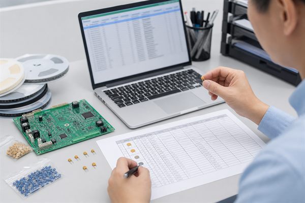
Useful RFQ details include:
- Schematic
- PCB layout files
- BOM with capacitance, voltage, dielectric, tolerance, and package
- Manufacturer part number if required
- Approved alternative brands
- Working voltage of the circuit
- Operating temperature range
- Application type, such as consumer, industrial, automotive, or medical device
- Prototype quantity and mass production estimate
- Any reliability or testing requirements
For EBest Circuit (Best Technology), complete capacitor information helps the team review component availability, assembly compatibility, BOM alternatives, and quotation accuracy before production starts.
FAQ
What does 104 mean on a ceramic capacitor?
104 means the capacitor value is 100,000pF, which equals 100nF or 0.1uF.
Is 104 the same as 0.1uF?
Yes. A 104 ceramic capacitor is the same nominal capacitance as a 0.1uF ceramic capacitor.
Is 104 the same as 100nF?
Yes. 104 equals 100nF.
Is a 104 ceramic capacitor polarized?
No. A normal ceramic capacitor 104 is non-polarized and can usually be installed in either direction.
What is the voltage rating of a 104 ceramic capacitor?
There is no single voltage rating for all 104 capacitors. Common voltage ratings may include 16V, 25V, 50V, 100V, 1kV, or higher. Always check the datasheet, circuit voltage, and BOM requirement.
Can I replace a 104 capacitor with a 0.1uF capacitor?
Yes, if the replacement also matches the required voltage rating, dielectric, tolerance, package size, and application conditions.
What is a ceramic disc capacitor 104?
A ceramic disc capacitor 104 is a leaded ceramic capacitor with a 0.1uF capacitance value. It is often used in through-hole circuits, repairs, education kits, and simple electronic products.
Is a 104 capacitor good for decoupling?
Yes. A 104 ceramic capacitor is commonly used for decoupling near IC power pins. For best performance, it should be placed close to the IC with short traces.
Are X7R and Y5V 104 capacitors the same?
No. They may have the same nominal 0.1uF value, but X7R is generally more stable over temperature than Y5V. Y5V can lose more capacitance under temperature and voltage conditions.
Can a 104 capacitor fail?
Yes. Failure can occur from overvoltage, cracking, poor soldering, mechanical stress, moisture damage, or using the wrong part for the circuit environment.
Why does my 104 capacitor not measure exactly 0.1uF?
Tolerance, dielectric type, test frequency, temperature, DC bias, and aging can all affect the measured value. A small difference is normal if it stays within the specified tolerance.
What should I write in a BOM instead of only “104”?
A better BOM line should include capacitance, voltage, dielectric, tolerance, package, and part number if needed. For example: 0.1uF, 50V, X7R, ±10%, 0603.
A 104 ceramic capacitor is a 0.1uF, 100nF, or 100,000pF capacitor, but that value alone is not enough for reliable PCB assembly. For real PCBA sourcing, buyers should also define voltage rating, dielectric, tolerance, package size, and approved alternatives.
If your BOM only lists “104” or you are not sure which 0.1uF ceramic capacitor is suitable for your PCB assembly, EBest Circuit (Best Technology) can help review the capacitance, voltage rating, dielectric, package, and approved alternatives before prototype or mass production. Contact us at sales@bestpcbs.com.